

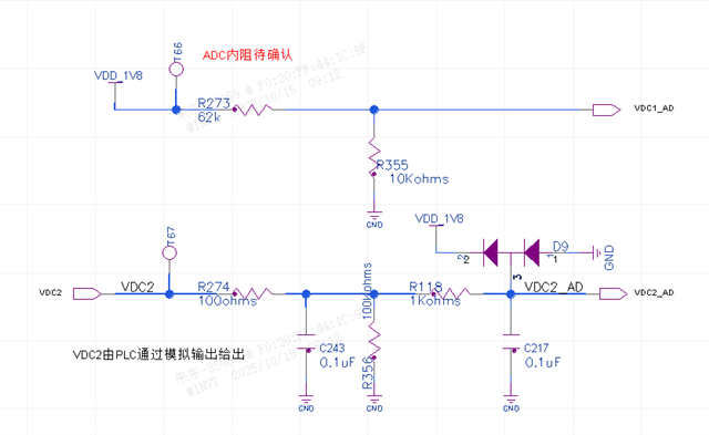
A1. The 1.8V voltage is divided by 62kΩ and 10kΩ resistors, resulting in a 0.25V voltage. This voltage can be measured with a multimeter.
A2. When this point is directly connected to ADC1, the voltage measured with a multimeter under two conditions—when the program is not loaded and when the program is loaded but the ADC is not sampling—is approximately 1.9V.
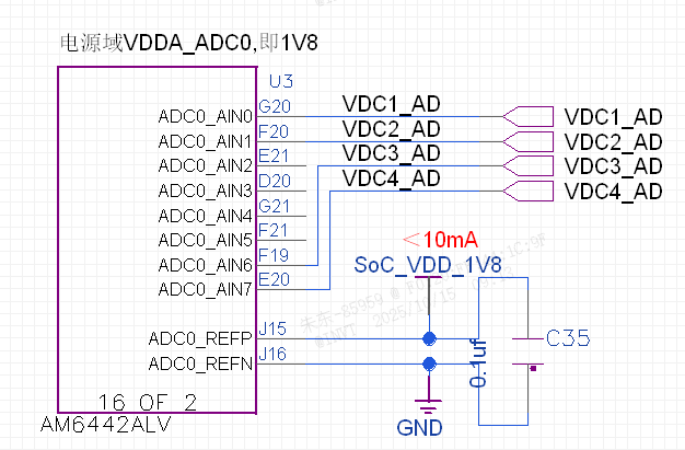
A3. When the ADC starts sampling, the voltage at this point, as measured directly with a multimeter, changes from 0.25V to approximately 0.6V (suspected to be caused by an internal 20kΩ pull-up resistor). The voltage read by the software is approximately 1.7V.
B1. A 0.8V analog output is provided by a PLC.
B2. This voltage is divided by the 100Ω, 1kΩ, and 100kΩ resistors as shown in the diagram. The voltage measured at the SoC's ADC pin with a multimeter is 0.86V, but the voltage value read by the software via the ADC is approximately 1V.
Please help confirm the possible causes:
-
What could cause the internal configuration of the ADC to deviate the pin voltage? For example, where can the internal pull-up or pull-down mode and resistance values be configured?
-
What could cause the voltage value read by the software via the ADC to deviate from the voltage value measured with a multimeter? Where can this test result be configured, calibrated, or corrected?
-
What might be the cause of the 1.9V voltage measured under condition A2?
