

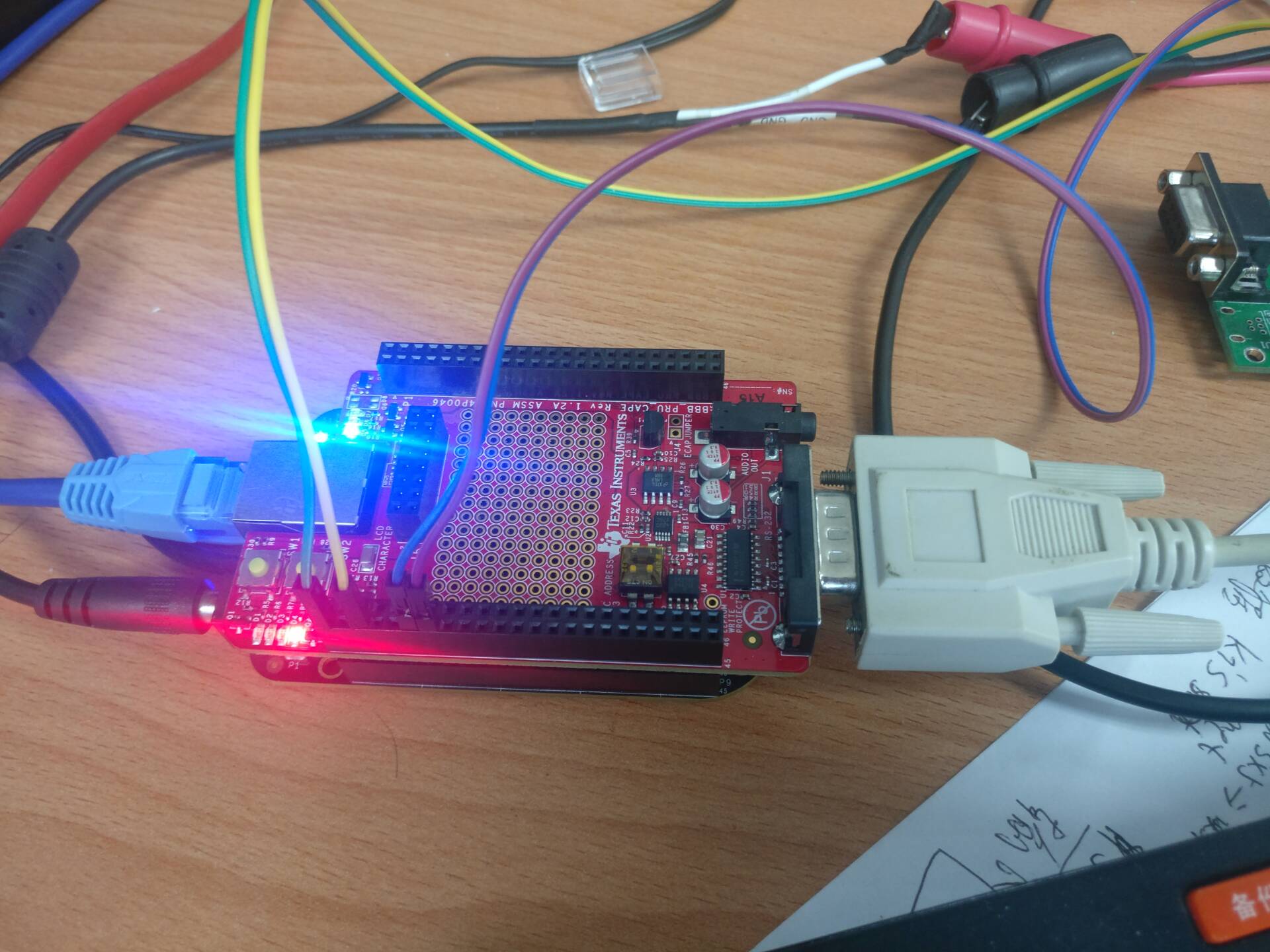
最近有需求需要用到am335x的pru,我在boneblack board 配合pru cape board 能跑通 pru的led 的例程,但唯独pru内部的uart(非sw uart)无法使用,请问有人使用过吗?
dts:
&am33xx_pinmux {
pru_cape_bone_pins: pru_cape_bone_pins {
pinctrl-single,pins = <
0x1a4 0x2e /* mcasp0_fsr, OMAP_MUX_MODE6 | AM33XX_PIN_INPUT, PRU CAPE SW1 */
0x1ac 0x2e /* mcasp0_ahclkx, OMAP_MUX_MODE6 | AM33XX_PIN_INPUT, PRU CAPE SW2 */
0x19c 0x05 /* mcasp0_ahclkr, OMAP_MUX_MODE5 | AM33XX_PIN_OUTPUT, PRU CAPE Red LED */
0x198 0x05 /* mcasp0_axr0, OMAP_MUX_MODE5 | AM33XX_PIN_OUTPUT, PRU CAPE Orange LED */
0x190 0x05 /* mcasp0_aclkx, OMAP_MUX_MODE5 | AM33XX_PIN_OUTPUT, PRU CAPE Blue LED */
0x194 0x05 /* mcasp0_fsx, OMAP_MUX_MODE5 | AM33XX_PIN_OUTPUT, PRU CAPE Green LED */
0x0ac 0x05 /* lcd_data3, OMAP_MUX_MODE5 | AM33XX_PIN_OUTPUT, PRU CAPE RGB_0 LED, HDMI Conf. */
0x0b0 0x05 /* lcd_data4, OMAP_MUX_MODE5 | AM33XX_PIN_OUTPUT, PRU CAPE RGB_1 LED, HDMI Conf. */
0x0b4 0x05 /* lcd_data5, OMAP_MUX_MODE5 | AM33XX_PIN_OUTPUT, PRU CAPE RGB_2 LED, HDMI Conf. */
0x0a0 0x05 /* lcd_data0, OMAP_MUX_MODE5 | AM33XX_PIN_OUTPUT, PRU CAPE Audio Data, HDMI Conf. */
0x0a4 0x05 /* lcd_data1, OMAP_MUX_MODE5 | AM33XX_PIN_OUTPUT, PRU CAPE Audio Clk, HDMI Conf. */
0x0a8 0x05 /* lcd_data2, OMAP_MUX_MODE5 | AM33XX_PIN_OUTPUT, PRU CAPE Audio Sync, HDMI Conf. */
0x184 0x05 /* uart1_txd, OMAP_MUX_MODE5 | AM33XX_PIN_OUTPUT, PRU CAPE PRU UART txd */
0x180 0x2d /* uart1_rxd, OMAP_MUX_MODE5 | AM33XX_PIN_INPUT, PRU CAPE PRU UART rxd */
0x154 0x04 /* spi0_d0, OMAP_MUX_MODE4 | AM33XX_PIN_OUTPUT, PRU CAPE PRU UART rts */
0x150 0x2c /* spi0_sclk, OMAP_MUX_MODE4 | AM33XX_PIN_INPUT, PRU CAPE PRU UART cts */
0x0b8 0x04 /* lcd_data6, OMAP_MUX_MODE4 | AM33XX_PIN_OUTPUT, PRU CAPE LCD rs t3 */
0x0e8 0x04 /* lcd_pclk, OMAP_MUX_MODE4 | AM33XX_PIN_OUTPUT, PRU CAPE LCD e v5 */
0x158 0x06 /* spi0_d1, OMAP_MUX_MODE6 | AM33XX_PIN_OUTPUT, PRU CAPE LCD data4 b16 */
0x15c 0x06 /* spi0_cs0, OMAP_MUX_MODE6 | AM33XX_PIN_OUTPUT, PRU CAPE LCD data5 a16 */
0x0e0 0x04 /* lcd_vsync, OMAP_MUX_MODE4 | AM33XX_PIN_OUTPUT, PRU CAPE LCD data6 u5 */
0x0e4 0x04 /* lcd_hsync, OMAP_MUX_MODE4 | AM33XX_PIN_OUTPUT, PRU CAPE LCD data7 r5 */
0x038 0x2e /* gpmc_ad14, OMAP_MUX_MODE6 | AM33XX_PIN_INPUT, PRU CAPE Temp Input */
/*0x0bc 0x04*/ /* lcd_data7, OMAP_MUX_MODE4 | AM33XX_PIN_OUTPUT, PRU CAPE Temp Output, Alpha Boards */
0x0ec 0x04 /* lcd_ac_bias_en, OMAP_MUX_MODE4 | AM33XX_PIN_OUTPUT, PRU Cape Temp Output */
>;
};
};
pru code:
#include <stdint.h>
#include <pru_cfg.h>
#include <pru_uart.h>
#include "resource_table_empty.h"
/* The FIFO size on the PRU UART is 16 bytes; however, we are (arbitrarily)
* only going to send 8 at a time */
#define FIFO_SIZE 16
#define MAX_CHARS 8
/* This hostBuffer structure is temporary but stores a data buffer */
struct {
uint8_t msg; // Not used today
uint8_t data[FIFO_SIZE];
} hostBuffer;
/* Making this buffer global will force the received data into memory */
uint8_t buffer[MAX_CHARS];
volatile register uint32_t __R30;
void main(void)
{
uint8_t tx;
uint8_t cnt;
uint32_t gpio;
/* Clear SYSCFG[STANDBY_INIT] to enable OCP master port */
CT_CFG.SYSCFG_bit.STANDBY_INIT = 0;
CT_CFG.CGR_bit.UART_CLK_EN = 1;
CT_CFG.CGR_bit.INTC_CLK_EN = 1;
gpio = 0x0008;
__R30 = 0x0;
__R30 ^= gpio;
__delay_cycles(100000000);
/* TODO: If modifying this to send data through the pins then PinMuxing
* needs to be taken care of prior to running this code.
* This is usually done via a GEL file in CCS or by the Linux driver */
/*** INITIALIZATION ***/
/* Set up UART to function at 115200 baud - DLL divisor is 104 at 16x oversample
* 192MHz / 104 / 16 = ~115200 */
CT_UART.DLL = 104;
CT_UART.DLH = 0;
CT_UART.MDR = 0x0;
/* Enable Interrupts in UART module. This allows the main thread to poll for
* Receive Data Available and Transmit Holding Register Empty */
CT_UART.IER = 0x7;
/* If FIFOs are to be used, select desired trigger level and enable
* FIFOs by writing to FCR. FIFOEN bit in FCR must be set first before
* other bits are configured */
/* Enable FIFOs for now at 1-byte, and flush them */
CT_UART.FCR = (0x8) | (0x4) | (0x2) | (0x1);
//CT_UART.FCR = (0x80) | (0x4) | (0x2) | (0x01); // 8-byte RX FIFO trigger
/* Choose desired protocol settings by writing to LCR */
/* 8-bit word, 1 stop bit, no parity, no break control and no divisor latch */
CT_UART.LCR = 3;
/* Enable loopback for test */
/*
* NOTE!
* loopback will prevent the UART from sending data to the output
* pins. Remember to disable loopback in the MCR register before
* looking for signals on your UART pins.
*/
CT_UART.MCR = 0x10;
/* Choose desired response to emulation suspend events by configuring
* FREE bit and enable UART by setting UTRST and URRST in PWREMU_MGMT */
/* Allow UART to run free, enable UART TX/RX */
CT_UART.PWREMU_MGMT = 0x6001;
/*** END INITIALIZATION ***/
/* Priming the 'hostbuffer' with a message */
hostBuffer.data[0] = 'H';
hostBuffer.data[1] = 'e';
hostBuffer.data[2] = 'l';
hostBuffer.data[3] = 'l';
hostBuffer.data[4] = 'o';
hostBuffer.data[5] = '!';
hostBuffer.data[6] = '!';
hostBuffer.data[7] = '!';
hostBuffer.data[8] = '!';
hostBuffer.data[9] = '!';
hostBuffer.data[10] = '\0';
/*** SEND SOME DATA ***/
while(1){
/* Let's send/receive some dummy data */
for (cnt = 0; cnt < MAX_CHARS; cnt++) {
//__delay_cycles(100000000);
//__R30 ^= gpio;
/* Load character, ensure it is not string termination */
if ((tx = hostBuffer.data[cnt]) == '\0')
break;
CT_UART.THR = tx;
/* Because we are doing loopback, wait until LSR.DR == 1
* indicating there is data in the RX FIFO */
while ((CT_UART.LSR & 0x1) == 0x0);
/* Read the value from RBR */
buffer[cnt] = CT_UART.RBR;
/* Wait for TX FIFO to be empty */
while (!((CT_UART.FCR & 0x2) == 0x2));
}
__R30 ^= gpio;
__delay_cycles(100000000);
}
/*** DONE SENDING DATA ***/
/* Disable UART before halting */
CT_UART.PWREMU_MGMT = 0x0;
/* Halt PRU core */
__halt();
}

