

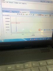
为什么DSP5509A采集得到的500Hz的正弦信号,CCS中的Graph显示的428Hz?采样频率为8k.
This thread has been locked.
If you have a related question, please click the "Ask a related question" button in the top right corner. The newly created question will be automatically linked to this question.
/******************************************************************************/
以下整个程序
/*----------------------------------------------------------------------------*/
/* DESCRIPTION: */
/* */
/* This is an example for EMIF of C5509 */
/*----------------------------------------------------------------------------*/
/* MODULE NAME... I2C and Mcbsp */
/* FILENAME...... codec.c */
/* DATE CREATED.. Mon 02/4/2004 */
/* COMPONENT..... */
/* PREREQUISITS.. */
/*----------------------------------------------------------------------------*/
/* DESCRIPTION: */
/* */
/* this example is that the codec is controled by the I2C and Mcbsp */
/*----------------------------------------------------------------------------*/
#include <csl.h>
#include <csl_i2c.h>
#include <stdio.h>
#include <csl_pll.h>
#include <csl_mcbsp.h>
#include <dsplib.h>
#define CODEC_ADDR 0x1A
#define nx 1024
void gengxin(DATA xn[nx], DATA x) {
int i = 0;
for (i = nx-1; i >=0; i--){
xn[i+1] = xn[i];
}
xn[0] = x;
}
//DATA xx[nx] = {-32768,-31744,-30720,-29696,-28672,-27648,-26624,-25600,-24576,-23552,-22528,-21504,-20480,-19456,
// -18432,-17408,-16384,-15360,-14336,-13312,-12288,-11264,-10240,-9216,-8192,-7168,-6144,-5120,-4096,-3072,
// -2048,-1024,0,1024,2048,3072,4096,5120,6144,7168,8192,9216,10240,11264,12288,13312,14336,15360,16384,17408,
// 18432,19456,20480,21504,22528,23552,24576,25600,26624,27648,28672,29696,30720,31744};
//DATA r[nx]={0};
/*锁相环的设置*/
PLL_Config myConfig = {
0, //IAI: the PLL locks using the same process that was underway
//before the idle mode was entered
1, //IOB: If the PLL indicates a break in the phase lock,
//it switches to its bypass mode and restarts the PLL phase-locking
//sequence
24, //PLL multiply value; multiply 24 times
1 //Divide by 2 PLL divide value; it can be either PLL divide value
//(when PLL is enabled), or Bypass-mode divide value
//(PLL in bypass mode, if PLL multiply value is set to 1)
};
unsigned int play_mode; // 0:play 1:record and play
MCBSP_Config Mcbsptest;
/*McBSP set,we use mcbsp1 to send and recieve the data between DSP and AIC23*/
MCBSP_Config Mcbsp1Config = {
MCBSP_SPCR1_RMK(
MCBSP_SPCR1_DLB_OFF, /* DLB = 0,禁止自闭环方式 */
MCBSP_SPCR1_RJUST_LZF, /* RJUST = 2 */
MCBSP_SPCR1_CLKSTP_DISABLE, /* CLKSTP = 0 */
MCBSP_SPCR1_DXENA_ON, /* DXENA = 1 */
0, /* ABIS = 0 */
MCBSP_SPCR1_RINTM_RRDY, /* RINTM = 0 */
0, /* RSYNCER = 0 */
MCBSP_SPCR1_RRST_DISABLE /* RRST = 0 */
),
MCBSP_SPCR2_RMK(
MCBSP_SPCR2_FREE_NO, /* FREE = 0 */
MCBSP_SPCR2_SOFT_NO, /* SOFT = 0 */
MCBSP_SPCR2_FRST_FSG, /* FRST = 0 */
MCBSP_SPCR2_GRST_CLKG, /* GRST = 0 */
MCBSP_SPCR2_XINTM_XRDY, /* XINTM = 0 */
0, /* XSYNCER = N/A */
MCBSP_SPCR2_XRST_DISABLE /* XRST = 0 */
),
/*单数据相,接受数据长度为16位,每相2个数据*/
MCBSP_RCR1_RMK(
MCBSP_RCR1_RFRLEN1_OF(1), /* RFRLEN1 = 1 */
MCBSP_RCR1_RWDLEN1_16BIT /* RWDLEN1 = 2 */
),
MCBSP_RCR2_RMK(
MCBSP_RCR2_RPHASE_SINGLE, /* RPHASE = 0 */
MCBSP_RCR2_RFRLEN2_OF(0), /* RFRLEN2 = 0 */
MCBSP_RCR2_RWDLEN2_8BIT, /* RWDLEN2 = 0 */
MCBSP_RCR2_RCOMPAND_MSB, /* RCOMPAND = 0 */
MCBSP_RCR2_RFIG_YES, /* RFIG = 0 */
MCBSP_RCR2_RDATDLY_1BIT /* RDATDLY = 1 */
),
MCBSP_XCR1_RMK(
MCBSP_XCR1_XFRLEN1_OF(1), /* XFRLEN1 = 1 */
MCBSP_XCR1_XWDLEN1_16BIT /* XWDLEN1 = 2 */
),
MCBSP_XCR2_RMK(
MCBSP_XCR2_XPHASE_SINGLE, /* XPHASE = 0 */
MCBSP_XCR2_XFRLEN2_OF(0), /* XFRLEN2 = 0 */
MCBSP_XCR2_XWDLEN2_8BIT, /* XWDLEN2 = 0 */
MCBSP_XCR2_XCOMPAND_MSB, /* XCOMPAND = 0 */
MCBSP_XCR2_XFIG_YES, /* XFIG = 0 */
MCBSP_XCR2_XDATDLY_1BIT /* XDATDLY = 1 */
),
MCBSP_SRGR1_DEFAULT,
MCBSP_SRGR2_DEFAULT,
MCBSP_MCR1_DEFAULT,
MCBSP_MCR2_DEFAULT,
MCBSP_PCR_RMK(
MCBSP_PCR_IDLEEN_RESET, /* IDLEEN = 0 */
MCBSP_PCR_XIOEN_SP, /* XIOEN = 0 */
MCBSP_PCR_RIOEN_SP, /* RIOEN = 0 */
MCBSP_PCR_FSXM_EXTERNAL, /* FSXM = 0 */
MCBSP_PCR_FSRM_EXTERNAL, /* FSRM = 0 */
0, /* DXSTAT = N/A */
MCBSP_PCR_CLKXM_INPUT, /* CLKXM = 0 */
MCBSP_PCR_CLKRM_INPUT, /* CLKRM = 0 */
MCBSP_PCR_SCLKME_NO, /* SCLKME = 0 */
MCBSP_PCR_FSXP_ACTIVEHIGH, /* FSXP = 0 */
MCBSP_PCR_FSRP_ACTIVEHIGH, /* FSRP = 1 */
MCBSP_PCR_CLKXP_FALLING, /* CLKXP = 1 */
MCBSP_PCR_CLKRP_RISING /* CLKRP = 1 */
),
MCBSP_RCERA_DEFAULT,
MCBSP_RCERB_DEFAULT,
MCBSP_RCERC_DEFAULT,
MCBSP_RCERD_DEFAULT,
MCBSP_RCERE_DEFAULT,
MCBSP_RCERF_DEFAULT,
MCBSP_RCERG_DEFAULT,
MCBSP_RCERH_DEFAULT,
MCBSP_XCERA_DEFAULT,
MCBSP_XCERB_DEFAULT,
MCBSP_XCERC_DEFAULT,
MCBSP_XCERD_DEFAULT,
MCBSP_XCERE_DEFAULT,
MCBSP_XCERF_DEFAULT,
MCBSP_XCERG_DEFAULT,
MCBSP_XCERH_DEFAULT
};
/* This next struct shows how to use the I2C API */
/* Create and initialize an I2C initialization structure */
I2C_Setup I2Cinit = {
0, /* 7 bit address mode */
0, /* own address - don't care if master */
84, /* clkout value (Mhz) */
50, /* a number between 10 and 400*/
0, /* number of bits/byte to be received or transmitted (8)*/
0, /* DLB mode on*/
1 /* FREE mode of operation on*/
};
I2C_Config testI2C;
/*数字音频接口格式设置
AIC23为主模式,数据为DSP模式,数据长度16位*/
Uint16 digital_audio_inteface_format[2]={0x0e,0x53};
/*AIC23的波特率设置,采样率为8K*/
Uint16 sample_rate_control[2] = {0x10,0x2e};
/*AIC23寄存器复位*/
Uint16 reset[2] ={0x1e,0x00};
/*AIC23节电方式设置,所有部分均所与工作状态*/
Uint16 power_down_control[2] ={0x0c,0x00};
/*AIC23模拟音频的控制
DAC使能,ADC输入选择为Line,mic输入,增益为0*/
Uint16 analog_aduio_path_control[2] ={0x08,0x14};
/*AIC23数字音频通路的控制*/
Uint16 digital_audio_path_control[2] ={0x0a,0x05};
/*AIC23数字接口的使能*/
Uint16 digital_interface_activation[2] ={0x12,0x01};
/*AIC23左通路音频调节*/
Uint16 left_line_input_volume_control[2] ={0x00,0x17};
/*AIC23右通路音频调节*/
Uint16 right_line_input_volume_control[2] ={0x02,0x17};
/*AIC23耳机左通路音频调节*/
Uint16 left_headphone_volume_control[2] ={0x05,0xFF};
/*AIC23耳机右通路音频调节*/
Uint16 right_headphone_volume_control[2] = {0x07,0xFF};
/*定义McBSP的句柄*/
MCBSP_Handle hMcbsp;
Uint16 i2c_status;
Uint16 i,temp;
DATA aic23data = 0;
DATA aic23data1[nx] = {0};
DATA aic23data2[nx] = {0};
void delay(Uint32 k)
{
while(k--);
}
void main(void)
{
i2c_status = 1;
/* Initialize CSL library - This is REQUIRED !!! */
/*初始化CSL库*/
CSL_init();
/*设置系统的运行速度为140MHz*/
PLL_config(&myConfig);
/* Initialize I2C, using parameters in init structure */
/*初始化I2C的格式*/
// I2C_config(&Config);
// I2C_start();
// I2C_getConfig(&Config1);
/*I2C is undet reset*/
I2C_RSET(I2CMDR,0);
/*设置预分频寄存器,I2C的mode clock is 10MHz*/
delay(100);
I2C_RSET(I2CSAR,0x001A);
I2C_RSET(I2CMDR,0x0620);
I2C_setup(&I2Cinit);
/*设置I2C的Mater clock*/
I2C_RSET(I2CCLKL,100);
I2C_RSET(I2CCLKH,100);
I2C_getConfig(&testI2C);
/*初始化McBSP0*/
hMcbsp = MCBSP_open(MCBSP_PORT1,MCBSP_OPEN_RESET);
/*设置McBSP0*/
MCBSP_config(hMcbsp,&Mcbsp1Config);
/*启动McBSP0*/
MCBSP_start(hMcbsp,
MCBSP_RCV_START | MCBSP_XMIT_START,
0);
MCBSP_getConfig(hMcbsp,&Mcbsptest);
/*reset AIC23*/
i2c_status = I2C_write( reset, //pointer to data array
2, //length of data to be transmitted
1, //master or slaver
CODEC_ADDR, //slave address to transmit to
1, //transfer mode of operation
30000 //time out for bus busy
);
delay(1000);
/*设置AIC23各部分均工作*/
i2c_status = I2C_write( power_down_control,//pointer to data array
2, //length of data to be transmitted
1, //master or slaver
CODEC_ADDR, //slave address to transmit to
1, //transfer mode of operation
30000 //time out for bus busy
);
/*设置AIC23的数字接口*/
i2c_status = I2C_write( digital_audio_inteface_format,//pointer to data array
2, //length of data to be transmitted
1, //master or slaver
CODEC_ADDR, //slave address to transmit to
1, //transfer mode of operation
30000 //time out for bus busy
);
/*设置AIC23模拟通路*/
i2c_status = I2C_write( analog_aduio_path_control,//pointer to data array
2, //length of data to be transmitted
1, //master or slaver
CODEC_ADDR, //slave address to transmit to
1, //transfer mode of operation
30000 //time out for bus busy
);
/*设置数字通路*/
i2c_status = I2C_write( digital_audio_path_control,//pointer to data array
2, //length of data to be transmitted
1, //master or slaver
CODEC_ADDR, //slave address to transmit to
1, //transfer mode of operation
30000 //time out for bus busy
);
/*设置AIC23的采样率*/
i2c_status = I2C_write( sample_rate_control,//pointer to data array
2, //length of data to be transmitted
1, //master or slaver
CODEC_ADDR, //slave address to transmit to
1, //transfer mode of operation
30000 //time out for bus busy
);
/*设置耳机音量*/
i2c_status = I2C_write( left_headphone_volume_control,//pointer to data array
2, //length of data to be transmitted
1, //master or slaver
CODEC_ADDR, //slave address to transmit to
1, //transfer mode of operation
30000 //time out for bus busy
);
i2c_status = I2C_write( right_headphone_volume_control,//pointer to data array
2, //length of data to be transmitted
1, //master or slaver
CODEC_ADDR, //slave address to transmit to
1, //transfer mode of operation
30000 //time out for bus busy
);
/*设置Line输入的音量*/
i2c_status = I2C_write( left_line_input_volume_control,//pointer to data array
2, //length of data to be transmitted
1, //master or slaver
CODEC_ADDR, //slave address to transmit to
1, //transfer mode of operation
30000 //time out for bus busy
);
i2c_status = I2C_write( right_line_input_volume_control,//pointer to data array
2, //length of data to be transmitted
1, //master or slaver
CODEC_ADDR, //slave address to transmit to
1, //transfer mode of operation
30000 //time out for bus busy
);
/*启动AIC23*/
i2c_status = I2C_write( digital_interface_activation,//pointer to data array
2, //length of data to be transmitted
1, //master or slaver
CODEC_ADDR, //slave address to transmit to
1, //transfer mode of operation
30000 //time out for bus busy
);
/*回放音频*/
int i = 0;
while(i<102400)
{
//sine(xx,r,nx);
// for (i=0;i<1024;i++){
while(!MCBSP_xrdy(hMcbsp)){};
aic23data = MCBSP_read16(hMcbsp);
gengxin(aic23data1,aic23data);
// gengxin(aic23data2,aic23data);
// rfft(aic23data1,nx, SCALE);
//for(temp=3000;temp>0;temp--);
while(!MCBSP_rrdy(hMcbsp)){};
MCBSP_write16(hMcbsp,aic23data);
// for (i=0;i<nx;i++){
// aic23data1[i] =aic23data;
// }
// }
i++;
}
}
void Delay(unsigned int nDelay)
{
unsigned int ii,jj,kk=0;
for ( ii=0;ii<nDelay;ii++ )
{
for ( jj=0;jj<2048;jj++ )
{
kk++;
}
}
}
/******************************************************************************\
* End of i2c2.c
\******************************************************************************/
这个问题建议到音频论坛咨询AIC23的配置问题。
https://e2echina.ti.com/support/audio/f/audio-forum
