我在裸核开发环境下,参考7242.K1_STK_v1.1的SPI驱动代码。
在仿真器环境调试下,没有编写如下RAM与PSC控制代码,依赖了仿真器的GET文件:
/*enable TSC, memory protection interrupts, EDC for internal RAM;
clear cache; protect L1 as cache*/
KeyStone_common_CPU_init();
/*print device information.
Enable memory protection interrupts, EDC for MSMC RAM*/
KeyStone_common_device_init();
//enable exception handling
KeyStone_Exception_cfg(TRUE);
CACHE_setL1PSize(CACHE_L1_32KCACHE);
CACHE_setL1DSize(CACHE_L1_32KCACHE);
CACHE_setL2Size(CACHE_128KCACHE);
/*clear configuration structure to default values*/
memset(&spiCfg, 0, sizeof(spiCfg));
memset(&spiIntCfg, 0, sizeof(spiIntCfg));
仿真器配置信息:
C66xx_0: GEL Output:
Connecting Target...
C66xx_0: GEL Output: DSP core #0
C66xx_0: GEL Output: C6678L GEL file Ver is 2.005
C66xx_0: GEL Output: Global Default Setup...
C66xx_0: GEL Output: Setup Cache...
C66xx_0: GEL Output: L1P = 32K
C66xx_0: GEL Output: L1D = 32K
C66xx_0: GEL Output: L2 = ALL SRAM
C66xx_0: GEL Output: Setup Cache... Done.
C66xx_0: GEL Output: Main PLL (PLL1) Setup ...
C66xx_0: GEL Output: PLL in Bypass ...
C66xx_0: GEL Output: PLL1 Setup for DSP @ 1000.0 MHz.
C66xx_0: GEL Output: SYSCLK2 = 333.3333 MHz, SYSCLK5 = 200.0 MHz.
C66xx_0: GEL Output: SYSCLK8 = 15.625 MHz.
C66xx_0: GEL Output: PLL1 Setup... Done.
C66xx_0: GEL Output: Power on all PSC modules and DSP domains...
C66xx_0: GEL Output: Power on all PSC modules and DSP domains... Done.
C66xx_0: GEL Output: DDR3 PLL (PLL2) Setup ...
C66xx_0: GEL Output: DDR3 PLL Setup... Done.
C66xx_0: GEL Output: DDR begin (1333 auto)
C66xx_0: GEL Output: XMC Setup ... Done
C66xx_0: GEL Output:
DDR3 initialization is complete.
C66xx_0: GEL Output: DDR done
C66xx_0: GEL Output: DDR3 memory test... Started
C66xx_0: GEL Output: DDR3 memory test... Passed
C66xx_0: GEL Output: PLL and DDR Initialization completed(0) ...
C66xx_0: GEL Output: Enabling EDC ...
C66xx_0: GEL Output: L1P error detection logic is enabled.
C66xx_0: GEL Output: L2 error detection/correction logic is enabled.
C66xx_0: GEL Output: MSMC error detection/correction logic is enabled.
C66xx_0: GEL Output: Enabling EDC ...Done
C66xx_0: GEL Output: Global Default Setup... Done.
现在程序运行后,通过DSP的SPI的SCK时钟管脚进行示波器测量,一直没有时钟信号,可测量到CS使能变化信号。
下面SPI的控制代码运行后相关寄存器配置写入或读取的数据信息如下:
[C66xx_0] main_pll_freq = 1000000000
SPI NOR FLASH test:
KeyStone_SPI_init_debug : gpSPI_regs->SPIGCR0 = 0x1
KeyStone_SPI_init_debug : gpSPI_regs->SPIPC0 = 0x1010e03
SPI_init: SPI PRESCALE= 5
KeyStone_SPI_init_debug : gpSPI_regs->SPIFMT[0] = 0x10508
SPI_init: SPI PRESCALE= 4
KeyStone_SPI_init_debug : gpSPI_regs->SPIFMT[1] = 0x40408
SPI_init: SPI PRESCALE= 3
KeyStone_SPI_init_debug : gpSPI_regs->SPIFMT[2] = 0x10308
SPI_init: SPI PRESCALE= 2
KeyStone_SPI_init_debug : gpSPI_regs->SPIFMT[3] = 0x40210
KeyStone_SPI_init_debug : gpSPI_regs->SPIDELAY = 0x0
KeyStone_SPI_init_debug : gpSPI_regs->SPIDEF = 0x3
KeyStone_SPI_init_debug : gpSPI_regs->SPIGCR1 = 0x1000003SPI NOR FLASH test at 48MHz...
KeyStone_SPI_TxRx_debug : gpSPI_regs->SPIDAT1 = 0x1602009f
KeyStone_SPI_TxRx_debug : gpSPI_regs->SPIBUF&0xFFFF= 0x18
KeyStone_SPI_TxRx_debug : length= 0x4
Read SPI NOR FLASH ID = 0xc8 0x65 0x18 0x32
KeyStone_SPI_TxRx_debug : gpSPI_regs->SPIDAT1 = 0x1602009f
KeyStone_SPI_TxRx_debug : gpSPI_regs->SPIBUF&0xFFFF= 0x18
KeyStone_SPI_TxRx_debug : length= 0x4
Read SPI NOR FLASH ID = 0xc8 0x65 0x18 0x32
KeyStone_SPI_TxRx_debug : gpSPI_regs->SPIDAT1 = 0x1602009f
KeyStone_SPI_TxRx_debug : gpSPI_regs->SPIBUF&0xFFFF= 0x18
KeyStone_SPI_TxRx_debug : length= 0x4
Read SPI NOR FLASH ID = 0xc8 0x65 0x18 0x32
现在确定几个问题:
1.SPI的默认是工作在PLL 的SYSCLK7 时钟频率下吗?
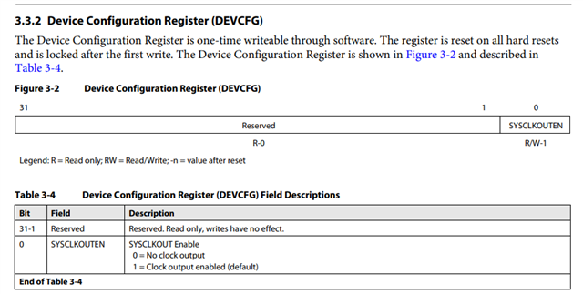
2.我非常疑惑是代码log读取到NOR flash( GD25WQ128E)OX9F信号了,但是在示波器下测量SPI的CLK测量无信号,后来怀疑PSC没有控制原因,现在增加控制代码,现象依旧。
请教下,可以在仿真状态可以测试量SPI端口的信号时序吗?
还有什么原因,可能造成SPI不同工作或时钟不输出吗?
static void psc_init(void)
{
/* Set psc as Always on state */
CSL_PSC_enablePowerDomain(CSL_PSC_PD_ALWAYSON);
/* Start state change */
CSL_PSC_startStateTransition(CSL_PSC_PD_ALWAYSON);
/* Wait until the status change is completed */
while(!CSL_PSC_isStateTransitionDone(CSL_PSC_PD_ALWAYSON));
/*
* SRIO power domain is turned OFF by default. It needs to be turned on before doing any
* SRIO device register access. This not required for the simulator
*/
/* Set SRIO Power domain to ON */
CSL_PSC_enablePowerDomain(CSL_PSC_PD_SRIO);
/* Enable the clocks too for SRIO */
CSL_PSC_setModuleNextState(CSL_PSC_LPSC_SRIO, PSC_MODSTATE_ENABLE);
/* Start the state transition */
CSL_PSC_startStateTransition(CSL_PSC_PD_SRIO);
/* Wait until the state transition process is completed. */
while(!CSL_PSC_isStateTransitionDone(CSL_PSC_PD_SRIO));
}


