If you have a related question, please click the "Ask a related question" button in the top right corner. The newly created question will be automatically linked to this question.
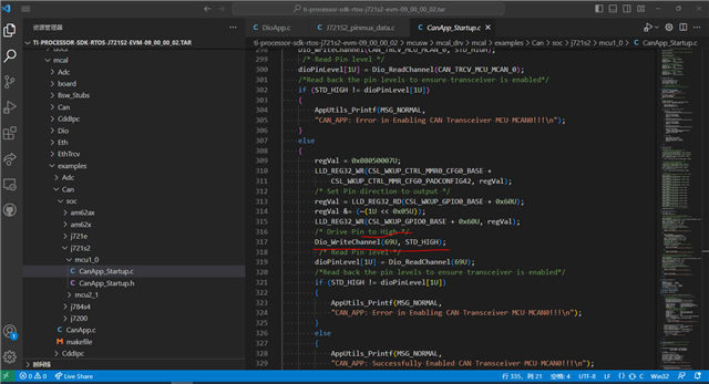
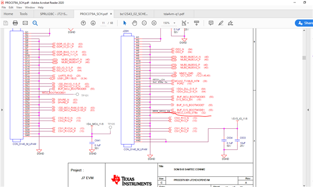
TDA4VL-Q1: How is the enable pin of the can transceiver mapped to the pin on the schematic diagram?
In general, the enable pin of the CAN transceiver is typically connected to a GPIO pin of the microcontroller or other controlling device. This GPIO pin can be configured as an output to control the enable/disable functionality of the CAN transceiver.