

Part Number: TMS320C6748
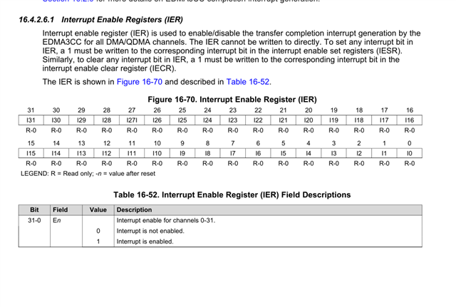
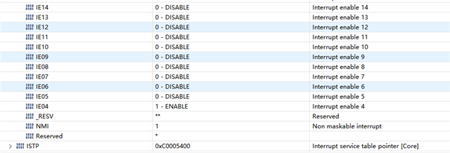
Why is the content of the IER table in the user manual different from that in CCS? In fact, I think CCS is correct, but in this case, I do not have the corresponding information and cannot program.
Original question:

Part Number: TMS320C6748
Why is the content of the IER table in the user manual different from that in CCS? In fact, I think CCS is correct, but in this case, I do not have the corresponding information and cannot program.

