

Part Number: AM625
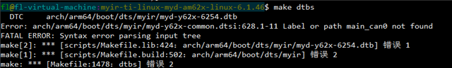
您好,我想在设备树中配置CAN,但是报错了,是不是我的配置方法有错误?下面是我的报错信息和修改代码
// SPDX-License-Identifier: GPL-2.0
/*
 * Common dtsi for AM62x SK and derivatives
 *
 * Copyright (C) 2021-2023 Texas Instruments Incorporated - https://www.ti.com/
 */

#include <dt-bindings/leds/common.h>
#include <dt-bindings/gpio/gpio.h>
#include <dt-bindings/net/ti-dp83867.h>
#include <dt-bindings/input/input.h>
#include "k3-am625.dtsi"

/ {
	aliases {
		can0 = &main_can0;
		serial2 = &main_uart0;
		serial3 = &main_uart1;
		serial6 = &main_uart4;
		serial8 = &main_uart6;
		mmc0 = &sdhci0;
		mmc1 = &sdhci1;
		mmc2 = &sdhci2;
		spi0 = &ospi0;
		ethernet0 = &cpsw_port1;
		ethernet1 = &cpsw_port2;
		usb0 = &usb0;
		usb1 = &usb1;
	};

	chosen {
		stdout-path = "serial2:115200n8";
		bootargs = "console=ttyS2,115200n8 earlycon=ns16550a,mmio32,0x02800000";
	};

	opp-table {
		/* Add 1.4GHz OPP for am625-sk board. Requires VDD_CORE to be at 0.85V */
		opp-1400000000 {
			opp-hz = /bits/ 64 <1400000000>;
			opp-supported-hw = <0x01 0x0004>;
			clock-latency-ns = <6000000>;
		};
	};

	memory@80000000 {
		device_type = "memory";
		/* 2G RAM */
		reg = <0x00000000 0x80000000 0x00000000 0x80000000>;

	};

	reserved-memory {
		#address-cells = <2>;
		#size-cells = <2>;
		ranges;

		ramoops@9c700000 {
			compatible = "ramoops";
			reg = <0x00 0x9c700000 0x00 0x00100000>;
			record-size = <0x8000>;
			console-size = <0x8000>;
			ftrace-size = <0x00>;
			pmsg-size = <0x8000>;
		};


		rtos_ipc_memory_region: ipc-memories@9c800000 {
			compatible = "shared-dma-pool";
			reg = <0x00 0x9c800000 0x00 0x00300000>;
			no-map;
		};

		mcu_m4fss_dma_memory_region: m4f-dma-memory@9cb00000 {
			compatible = "shared-dma-pool";
			reg = <0x00 0x9cb00000 0x00 0x100000>;
			no-map;
		};

		mcu_m4fss_memory_region: m4f-memory@9cc00000 {
			compatible = "shared-dma-pool";
			reg = <0x00 0x9cc00000 0x00 0xe00000>;
			no-map;
		};

		wkup_r5fss0_core0_dma_memory_region: r5f-dma-memory@9da00000 {
			compatible = "shared-dma-pool";
			reg = <0x00 0x9da00000 0x00 0x00100000>;
			no-map;
		};

		wkup_r5fss0_core0_memory_region: r5f-memory@9db00000 {
			compatible = "shared-dma-pool";
			reg = <0x00 0x9db00000 0x00 0x00c00000>;
			no-map;
		};

		lpm_ctx_ddr: lpm-memory@9e700000 {
			reg = <0x00 0x9e700000 0x00 0x80000>;
			alignment = <0x1000>;
		};

		secure_tfa_ddr: tfa@9e780000 {
			reg = <0x00 0x9e780000 0x00 0x80000>;
			alignment = <0x1000>;
			no-map;
		};

		secure_ddr: optee@9e800000 {
			reg = <0x00 0x9e800000 0x00 0x01800000>; /* for OP-TEE */
			alignment = <0x1000>;
			no-map;
		};

		framebuffer: framebuffer@ff700000 {
			reg = <0x00 0xff700000 0x00 0x008ca000>;
			no-map;
		};
	};

	vmain_pd: regulator-0 {
		compatible = "regulator-fixed";
		regulator-name = "vmain_pd";
		regulator-min-microvolt = <5000000>;
		regulator-max-microvolt = <5000000>;
		regulator-always-on;
		regulator-boot-on;
	};

	vcc_5v0: regulator-1 {
		compatible = "regulator-fixed";
		regulator-name = "vcc_5v0";
		regulator-min-microvolt = <5000000>;
		regulator-max-microvolt = <5000000>;
		vin-supply = <&vmain_pd>;
		regulator-always-on;
		regulator-boot-on;
	};

	vcc_3v3_sys: regulator-2 {
		compatible = "regulator-fixed";
		regulator-name = "vcc_3v3_sys";
		regulator-min-microvolt = <3300000>;
		regulator-max-microvolt = <3300000>;
		vin-supply = <&vmain_pd>;
		regulator-always-on;
		regulator-boot-on;
	};

	vdd_mmc1: regulator-3 {
		compatible = "regulator-fixed";
		regulator-name = "vdd_mmc1";
		regulator-min-microvolt = <3300000>;
		regulator-max-microvolt = <3300000>;
		regulator-boot-on;
		enable-active-high;
		vin-supply = <&vcc_3v3_sys>;
	};

	vdd_sd_dv: regulator-sd {
		compatible = "regulator-fixed";
		regulator-name = "vdd_sd_dv";
		regulator-min-microvolt = <3300000>;
		regulator-max-microvolt = <3300000>;
		regulator-boot-on;
		enable-active-high;
		vin-supply = <&vcc_3v3_sys>;
	};

	vdd_wl_dv: regulator-wl {
		compatible = "regulator-fixed";
		regulator-name = "vdd_wl_dv";
		regulator-min-microvolt = <3300000>;
		regulator-max-microvolt = <3300000>;
		regulator-boot-on;
		enable-active-high;
		vin-supply = <&vcc_3v3_sys>;
	};

	wlan_reg_on: regulator-4 {
		compatible = "regulator-fixed";
		regulator-name = "wlan_reg_on";
		regulator-min-microvolt = <3300000>;
		regulator-max-microvolt = <3300000>;
		enable-active-high;
		regulator-boot-on;
		vin-supply = <&vcc_3v3_sys>;
		pinctrl-names = "default";
		pinctrl-1 = <&mcu_wlan_reg_on_pins_default>;
		gpios = <&mcu_gpio0 15 GPIO_ACTIVE_HIGH>;
	};

	vcc_1v8: regulator-5 {
		compatible = "regulator-fixed";
		regulator-name = "vcc_1v8";
		regulator-min-microvolt = <1800000>;
		regulator-max-microvolt = <1800000>;
		vin-supply = <&vcc_3v3_sys>;
		regulator-always-on;
		regulator-boot-on;
	};

	lvds_power: regulator-6 {
		compatible = "regulator-fixed";
		regulator-name = "lvds_power";
		regulator-min-microvolt = <3300000>;
		regulator-max-microvolt = <3300000>;
		enable-active-high;
		regulator-always-on;
		regulator-boot-on;
		vin-supply = <&vcc_5v0>;
		pinctrl-names = "default";
		pinctrl-1 = <&mcu_lvds_power_pins_default>;
		gpios = <&mcu_gpio0 4 GPIO_ACTIVE_HIGH>;
	};

	csi1_io: csi1-io {
		compatible = "regulator-fixed";
		regulator-name = "csi1_pwr";
		regulator-min-microvolt = <3300000>;
		regulator-max-microvolt = <3300000>;
		gpio = <&mcu_gpio0 3 GPIO_ACTIVE_HIGH>;
		enable-active-high;
		regulator-always-on;
		pinctrl-names = "default";
		pinctrl-1 = <&csi_io_power_pins_default>;
	};


	hdmi: connector {
		compatible = "hdmi-connector";
		label = "hdmi";
		type = "a";
		port {
			hdmi_connector_in: endpoint {
				remote-endpoint = <&sii9022_out>;
			};
		};
	};

	clk_ov5640_fixed: ov5640-xclk {
		compatible = "fixed-clock";
		#clock-cells = <0>;
		clock-frequency = <12000000>;
	};

	sgtl5000_mclk: sgtl5000-mclk {
		compatible = "fixed-clock";
		#clock-cells = <0>;
		clock-frequency = <11289600>;
	};

	codec_audio: sound {
		compatible = "simple-audio-card";
		simple-audio-card,name = "AM62x-SKEVM";
		simple-audio-card,widgets =
				"Microphone", "Microphone Jack",
				"Headphone", "Headphone Jack",
				"Speaker", "Speaker Ext",
				"Line", "Line In Jack";
		simple-audio-card,routing =
				"MIC_IN", "Microphone Jack",
				"Microphone Jack", "Mic Bias",
				"LINE_IN", "Line In Jack",
				"Headphone Jack", "HP_OUT",
				"Speaker Ext", "LINE_OUT";
		simple-audio-card,format = "i2s";
		simple-audio-card,mclk-fs = <256>;
		simple-audio-card,bitclock-master = <&sound_master>;
		simple-audio-card,frame-master = <&sound_master>;
		simple-audio-card,bitclock-inversion;

		simple-audio-card,cpu {
			sound-dai = <&mcasp0>;
		};

		sound_master: simple-audio-card,codec {
			sound-dai = <&sgtl5000>;
			clocks = <&sgtl5000_mclk>;
		};
	};

	leds {
		compatible = "gpio-leds";

		led-user {
			label = "am62-sk:d54";
			gpios = <&at9555 4 GPIO_ACTIVE_LOW>;
			max-brightness = <255>;
			linux,default-trigger = "heartbeat";
			function = LED_FUNCTION_HEARTBEAT;
			default-state = "off";
		};

		led-sys {
			label = "am62-sk:d53";
			pinctrl-names = "default";
			pinctrl-1 = <&mcu_run_led_pins_default>;
			gpios = <&mcu_gpio0 16 GPIO_ACTIVE_LOW>;
			linux,default-trigger = "heartbeat";
			function = LED_FUNCTION_HEARTBEAT;
			default-state = "on";
		};
	};

	gpio-keys {
		compatible = "gpio-keys";
		autorepeat;
		pinctrl-names = "default";
		pinctrl-0 = <&main_user_key_pins_default>;

		user: user {
			label = "GPIO Key USER1";
			linux,code = <BTN_0>;
			gpios = <&main_gpio0 36 GPIO_ACTIVE_LOW>;
		};
	};
};

&main_pmx0 {
	/* First pad number is ALW package and second is AMC package */
	main_uart0_pins_default: main-uart0-pins-default {
		pinctrl-single,pins = <
			AM62X_IOPAD(0x1c8, PIN_INPUT, 0) /* (D14/A13) UART0_RXD */
			AM62X_IOPAD(0x1cc, PIN_OUTPUT, 0) /* (E14/E11) UART0_TXD */
		>;
	};

	main_uart1_pins_default: main-uart1-pins-default {
		pinctrl-single,pins = <
			AM62X_IOPAD(0x0194, PIN_INPUT, 2) /* (B19) MCASP0_AXR3.UART1_CTSn */
			AM62X_IOPAD(0x0198, PIN_OUTPUT, 2) /* (A19) MCASP0_AXR2.UART1_RTSn */
			AM62X_IOPAD(0x01ac, PIN_INPUT, 2) /* (E19) MCASP0_AFSR.UART1_RXD */
			AM62X_IOPAD(0x01b0, PIN_OUTPUT, 2) /* (A20) MCASP0_ACLKR.UART1_TXD */
		>;
	};

	main_uart4_pins_default: main-uart4-pins-default {
		pinctrl-single,pins = <
			AM62X_IOPAD(0x00b0, PIN_INPUT, 3) /* (K22) GPMC0_CSn2.UART4_RXD */
			AM62X_IOPAD(0x00b4, PIN_OUTPUT, 3) /* (K24) GPMC0_CSn3.UART4_TXD */
		>;
	};

	main_uart4_rst_pins_default: main-uart4-rst-pins-default {
		pinctrl-single,pins = <
			AM62X_IOPAD(0x0030, PIN_INPUT, 7) /* (G21) OSPI0_CSn1.GPIO0_12 */
		>;
	};

	main_uart6_pins_default: main-uart6-pins-default {
		pinctrl-single,pins = <
			AM62X_IOPAD(0x009c, PIN_INPUT, 3) /* (V25) GPMC0_WAIT1.UART6_RXD */
			AM62X_IOPAD(0x00a0, PIN_OUTPUT, 3) /* (K25) GPMC0_WPn.UART6_TXD */
		>;
	};

	main_uart6_rst_pins_default: main-uart6-rst-pins-default {
		pinctrl-single,pins = <
			AM62X_IOPAD(0x0258, PIN_INPUT, 7) /* (F18) USB1_DRVVBUS.GPIO1_51 */
		>;
	};

	main_i2c0_pins_default: main-i2c0-pins-default {
		pinctrl-single,pins = <
			AM62X_IOPAD(0x1e0, PIN_INPUT_PULLUP, 0) /* (B16/E12) I2C0_SCL */
			AM62X_IOPAD(0x1e4, PIN_INPUT_PULLUP, 0) /* (A16/D14) I2C0_SDA */
		>;
	};

	main_i2c1_pins_default: main-i2c1-pins-default {
		pinctrl-single,pins = <
			AM62X_IOPAD(0x1e8, PIN_INPUT_PULLUP, 0) /* (B17/A17) I2C1_SCL */
			AM62X_IOPAD(0x1ec, PIN_INPUT_PULLUP, 0) /* (A17/A16) I2C1_SDA */
		>;
	};

	main_i2c3_pins_default: main-i2c3-pins-default {
		pinctrl-single,pins = <
			AM62X_IOPAD(0x1d0, PIN_INPUT_PULLUP, 2) /* (A15) UART0_CTSn.I2C3_SCL */
			AM62X_IOPAD(0x1d4, PIN_INPUT_PULLUP, 2) /* (B15) UART0_RTSn.I2C3_SDA */
		>;
	};

	main_mmc0_pins_default: main-mmc0-pins-default {
		pinctrl-single,pins = <
			AM62X_IOPAD(0x220, PIN_INPUT, 0) /* (Y3/V3) MMC0_CMD */
			AM62X_IOPAD(0x218, PIN_INPUT, 0) /* (AB1/Y1) MMC0_CLK */
			AM62X_IOPAD(0x214, PIN_INPUT, 0) /* (AA2/V2) MMC0_DAT0 */
			AM62X_IOPAD(0x210, PIN_INPUT, 0) /* (AA1/V1) MMC0_DAT1 */
			AM62X_IOPAD(0x20c, PIN_INPUT, 0) /* (AA3/W2) MMC0_DAT2 */
			AM62X_IOPAD(0x208, PIN_INPUT, 0) /* (Y4/W1) MMC0_DAT3 */
			AM62X_IOPAD(0x204, PIN_INPUT, 0) /* (AB2/Y2) MMC0_DAT4 */
			AM62X_IOPAD(0x200, PIN_INPUT, 0) /* (AC1/W3) MMC0_DAT5 */
			AM62X_IOPAD(0x1fc, PIN_INPUT, 0) /* (AD2/W4) MMC0_DAT6 */
			AM62X_IOPAD(0x1f8, PIN_INPUT, 0) /* (AC2/V4) MMC0_DAT7 */
		>;
	};

	main_mmc1_pins_default: main-mmc1-pins-default {
		pinctrl-single,pins = <
			AM62X_IOPAD(0x23c, PIN_INPUT, 0) /* (A21/C18) MMC1_CMD */
			AM62X_IOPAD(0x234, PIN_INPUT, 0) /* (B22/A20) MMC1_CLK */
			AM62X_IOPAD(0x230, PIN_INPUT, 0) /* (A22/A19) MMC1_DAT0 */
			AM62X_IOPAD(0x22c, PIN_INPUT, 0) /* (B21/B19) MMC1_DAT1 */
			AM62X_IOPAD(0x228, PIN_INPUT, 0) /* (C21/B20) MMC1_DAT2 */
			AM62X_IOPAD(0x224, PIN_INPUT, 0) /* (D22/C19) MMC1_DAT3 */
			AM62X_IOPAD(0x240, PIN_INPUT, 0) /* (D17/C15) MMC1_SDCD */
		>;
	};

	main_mmc2_pins_default: main-mmc2-pins-default {
		pinctrl-single,pins = <
			AM62X_IOPAD(0x120, PIN_INPUT, 0) /* (C24) MMC2_CMD */
			AM62X_IOPAD(0x118, PIN_INPUT, 0) /* (D25) MMC2_CLK */
			AM62X_IOPAD(0x114, PIN_INPUT, 0) /* (B24) MMC2_DAT0 */
			AM62X_IOPAD(0x110, PIN_INPUT, 0) /* (C25) MMC2_DAT1 */
			AM62X_IOPAD(0x10c, PIN_INPUT, 0) /* (E23) MMC2_DAT2 */
			AM62X_IOPAD(0x108, PIN_INPUT, 0) /* (D24) MMC2_DAT3 */
			AM62X_IOPAD(0x11c, PIN_INPUT, 0) /* (#N/A) MMC2_CLKB */
		>;
	};

	main_mdio1_pins_default: main-mdio1-pins-default {
		pinctrl-single,pins = <
			AM62X_IOPAD(0x160, PIN_OUTPUT, 0) /* (AD24/V17) MDIO0_MDC */
			AM62X_IOPAD(0x15c, PIN_INPUT, 0) /* (AB22/U16) MDIO0_MDIO */
		>;
	};

	main_rgmii1_pins_default: main-rgmii1-pins-default {
		pinctrl-single,pins = <
			AM62X_IOPAD(0x14c, PIN_INPUT, 0) /* (AB17/W15) RGMII1_RD0 */
			AM62X_IOPAD(0x150, PIN_INPUT, 0) /* (AC17/Y16) RGMII1_RD1 */
			AM62X_IOPAD(0x154, PIN_INPUT, 0) /* (AB16/AA17) RGMII1_RD2 */
			AM62X_IOPAD(0x158, PIN_INPUT, 0) /* (AA15/Y15) RGMII1_RD3 */
			AM62X_IOPAD(0x148, PIN_INPUT, 0) /* (AD17/AA16) RGMII1_RXC */
			AM62X_IOPAD(0x144, PIN_INPUT, 0) /* (AE17/W14) RGMII1_RX_CTL */
			AM62X_IOPAD(0x134, PIN_OUTPUT, 0) /* (AE20/U14) RGMII1_TD0 */
			AM62X_IOPAD(0x138, PIN_OUTPUT, 0) /* (AD20/AA19) RGMII1_TD1 */
			AM62X_IOPAD(0x13c, PIN_OUTPUT, 0) /* (AE18/Y17) RGMII1_TD2 */
			AM62X_IOPAD(0x140, PIN_OUTPUT, 0) /* (AD18/AA18) RGMII1_TD3 */
			AM62X_IOPAD(0x130, PIN_OUTPUT, 0) /* (AE19/W16) RGMII1_TXC */
			AM62X_IOPAD(0x12c, PIN_OUTPUT, 0) /* (AD19/V15) RGMII1_TX_CTL */
		>;
	};

	main_rgmii2_pins_default: main-rgmii2-pins-default {
		pinctrl-single,pins = <
			AM62X_IOPAD(0x184, PIN_INPUT, 0) /* (AE23) RGMII2_RD0 */
			AM62X_IOPAD(0x188, PIN_INPUT, 0) /* (AB20) RGMII2_RD1 */
			AM62X_IOPAD(0x18c, PIN_INPUT, 0) /* (AC21) RGMII2_RD2 */
			AM62X_IOPAD(0x190, PIN_INPUT, 0) /* (AE22) RGMII2_RD3 */
			AM62X_IOPAD(0x180, PIN_INPUT, 0) /* (AD23) RGMII2_RXC */
			AM62X_IOPAD(0x17c, PIN_INPUT, 0) /* (AD22) RGMII2_RX_CTL */
			AM62X_IOPAD(0x16c, PIN_OUTPUT, 0) /* (Y18) RGMII2_TD0 */
			AM62X_IOPAD(0x170, PIN_OUTPUT, 0) /* (AA18) RGMII2_TD1 */
			AM62X_IOPAD(0x174, PIN_OUTPUT, 0) /* (AD21) RGMII2_TD2 */
			AM62X_IOPAD(0x178, PIN_OUTPUT, 0) /* (AC20) RGMII2_TD3 */
			AM62X_IOPAD(0x168, PIN_OUTPUT, 0) /* (AE21) RGMII2_TXC */
			AM62X_IOPAD(0x164, PIN_OUTPUT, 0) /* (AA19) RGMII2_TX_CTL */
		>;
	};

	ospi0_pins_default: ospi0-pins-default {
		pinctrl-single,pins = <
			AM62X_IOPAD(0x000, PIN_OUTPUT, 0) /* (H24) OSPI0_CLK */
			AM62X_IOPAD(0x02c, PIN_OUTPUT, 0) /* (F23) OSPI0_CSn0 */
			AM62X_IOPAD(0x00c, PIN_INPUT, 0) /* (E25) OSPI0_D0 */
			AM62X_IOPAD(0x010, PIN_INPUT, 0) /* (G24) OSPI0_D1 */
			AM62X_IOPAD(0x014, PIN_INPUT, 0) /* (F25) OSPI0_D2 */
			AM62X_IOPAD(0x018, PIN_INPUT, 0) /* (F24) OSPI0_D3 */
			AM62X_IOPAD(0x01c, PIN_INPUT, 0) /* (J23) OSPI0_D4 */
			AM62X_IOPAD(0x020, PIN_INPUT, 0) /* (J25) OSPI0_D5 */
			AM62X_IOPAD(0x024, PIN_INPUT, 0) /* (H25) OSPI0_D6 */
			AM62X_IOPAD(0x028, PIN_INPUT, 0) /* (J22) OSPI0_D7 */
			AM62X_IOPAD(0x008, PIN_INPUT, 0) /* (J24) OSPI0_DQS */
			AM62X_IOPAD(0x038, PIN_INPUT, 2) /* (E24) OSPI0_CSn3.OSPI0_ECC_FAIL */
		>;
	};

	main_dss0_pins_default: main-dss0-pins-default {
		pinctrl-single,pins = <
			AM62X_IOPAD(0x0100, PIN_OUTPUT, 0) /* (AC25) VOUT0_VSYNC */
			AM62X_IOPAD(0x00f8, PIN_OUTPUT, 0) /* (AB24) VOUT0_HSYNC */
			AM62X_IOPAD(0x0104, PIN_OUTPUT, 0) /* (AC24) VOUT0_PCLK */
			AM62X_IOPAD(0x00fc, PIN_OUTPUT, 0) /* (Y20) VOUT0_DE */
			AM62X_IOPAD(0x00b8, PIN_OUTPUT, 0) /* (U22) VOUT0_DATA0 */
			AM62X_IOPAD(0x00bc, PIN_OUTPUT, 0) /* (V24) VOUT0_DATA1 */
			AM62X_IOPAD(0x00c0, PIN_OUTPUT, 0) /* (W25) VOUT0_DATA2 */
			AM62X_IOPAD(0x00c4, PIN_OUTPUT, 0) /* (W24) VOUT0_DATA3 */
			AM62X_IOPAD(0x00c8, PIN_OUTPUT, 0) /* (Y25) VOUT0_DATA4 */
			AM62X_IOPAD(0x00cc, PIN_OUTPUT, 0) /* (Y24) VOUT0_DATA5 */
			AM62X_IOPAD(0x00d0, PIN_OUTPUT, 0) /* (Y23) VOUT0_DATA6 */
			AM62X_IOPAD(0x00d4, PIN_OUTPUT, 0) /* (AA25) VOUT0_DATA7 */
			AM62X_IOPAD(0x00d8, PIN_OUTPUT, 0) /* (V21) VOUT0_DATA8 */
			AM62X_IOPAD(0x00dc, PIN_OUTPUT, 0) /* (W21) VOUT0_DATA9 */
			AM62X_IOPAD(0x00e0, PIN_OUTPUT, 0) /* (V20) VOUT0_DATA10 */
			AM62X_IOPAD(0x00e4, PIN_OUTPUT, 0) /* (AA23) VOUT0_DATA11 */
			AM62X_IOPAD(0x00e8, PIN_OUTPUT, 0) /* (AB25) VOUT0_DATA12 */
			AM62X_IOPAD(0x00ec, PIN_OUTPUT, 0) /* (AA24) VOUT0_DATA13 */
			AM62X_IOPAD(0x00f0, PIN_OUTPUT, 0) /* (Y22) VOUT0_DATA14 */
			AM62X_IOPAD(0x00f4, PIN_OUTPUT, 0) /* (AA21) VOUT0_DATA15 */
			AM62X_IOPAD(0x005c, PIN_OUTPUT, 1) /* (R24) GPMC0_AD8.VOUT0_DATA16 */
			AM62X_IOPAD(0x0060, PIN_OUTPUT, 1) /* (R25) GPMC0_AD9.VOUT0_DATA17 */
			AM62X_IOPAD(0x0064, PIN_OUTPUT, 1) /* (T25) GPMC0_AD10.VOUT0_DATA18 */
			AM62X_IOPAD(0x0068, PIN_OUTPUT, 1) /* (R21) GPMC0_AD11.VOUT0_DATA19 */
			AM62X_IOPAD(0x006c, PIN_OUTPUT, 1) /* (T22) GPMC0_AD12.VOUT0_DATA20 */
			AM62X_IOPAD(0x0070, PIN_OUTPUT, 1) /* (T24) GPMC0_AD13.VOUT0_DATA21 */
			AM62X_IOPAD(0x0074, PIN_OUTPUT, 1) /* (U25) GPMC0_AD14.VOUT0_DATA22 */
			AM62X_IOPAD(0x0078, PIN_OUTPUT, 1) /* (U24) GPMC0_AD15.VOUT0_DATA23 */
		>;
	};


	main_mcasp1_pins_default: main-mcasp1-pins-default {
		pinctrl-single,pins = <
			AM62X_IOPAD(0x0090, PIN_INPUT, 2) /* (M24) GPMC0_BE0N_CLE.MCASP1_ACLKX */
			AM62X_IOPAD(0x0098, PIN_INPUT, 2) /* (U23) GPMC0_WAIT0.MCASP1_AFSX */
			AM62X_IOPAD(0x008c, PIN_OUTPUT, 2) /* (L25) GPMC0_WEN.MCASP1_AXR0 */
			AM62X_IOPAD(0x0084, PIN_INPUT, 2) /* (L23) GPMC0_ADVN_ALE.MCASP1_AXR2 */
		>;
	};

	main_mcasp0_pins_default: main-mcasp0-pins-default {
		pinctrl-single,pins = <
			AM62X_IOPAD(0x01a4, PIN_INPUT, 0) /* (B20) MCASP0_ACLKX.MCASP0_ACLKX */
			AM62X_IOPAD(0x01a8, PIN_INPUT, 0) /* (D20) MCASP0_AFSX.MCASP0_AFSX */
			AM62X_IOPAD(0x01a0, PIN_OUTPUT, 0) /* (E18) MCASP0_AXR0.MCASP0_AXR0 */
			AM62X_IOPAD(0x019c, PIN_INPUT, 0) /* (B18) MCASP0_AXR1.MCASP0_AXR1 */
		>;
	};

	main_ptn5150_vbus_pins_default: main-ptn5150-vbus-pins-default {
		pinctrl-single,pins = <
			AM62X_IOPAD(0x254, PIN_OUTPUT, 7) /* (C20) USB0_DRVVBUS.GPIO1_50 */
			AM62X_IOPAD(0x124, PIN_INPUT, 7) /* (A23) MMC2_SDCD.GPIO0_71 */

		>;
	};
	main_user_key_pins_default: main-user-key-pins-default {
		pinctrl-single,pins = <
			AM62X_IOPAD(0x0094, PIN_INPUT, 7) /* (N20) GPMC0_BE1n.GPIO0_36 */
		>;
	};

	main_mcan0_pins_default: main_mcan0_pins_default {
		pinctrl-single,pins = <
			AM62X_IOPAD(0x01d8, PIN_OUTPUT, 0) /* (C15) SoC_UART1_DTRn.MCAN0_TX */
			AM62X_IOPAD(0x01dc, PIN_INPUT, 0) /* (E15) SoC_UART1_RIn.MCAN0_RX */
		>;
	};
};

&mcu_pmx0 {


	mcu_mcan0_pins_default: mcu_mcan0_pins_default {
		pinctrl-single,pins = <
			AM62X_MCU_IOPAD(0x0034, PIN_OUTPUT, 7) /* (D6) MCU_MCAN0_TX */
			AM62X_MCU_IOPAD(0x0038, PIN_INPUT, 7) /* (B3) MCU_MCAN0_RX */
		>;
	};

	mcu_i2c0_pins_default: mcu-i2c0-pins-default {
		pinctrl-single,pins = <
			AM62X_MCU_IOPAD(0x0044, PIN_INPUT, 0) /* (A8) MCU_I2C0_SCL */
			AM62X_MCU_IOPAD(0x0048, PIN_INPUT, 0) /* (D10) MCU_I2C0_SDA */
		>;
	};

	mcu_wlan_reg_on_pins_default: mcu-wl-reg-on-pins-default {
		pinctrl-single,pins = <
			AM62X_MCU_IOPAD(0x003c, PIN_OUTPUT_PULLUP, 7) /* (E5) MCU_MCAN1_TX.MCU_GPIO0_15 */
		>;
	};

	mcu_lvds_power_pins_default: mcu-lvds-power-pins-default {
		pinctrl-single,pins = <
			AM62X_MCU_IOPAD(0x0010, PIN_OUTPUT_PULLUP, 7) /* (C9) MCU_SPI0_D1.MCU_GPIO0_4 */
		>;
	};
	csi_io_power_pins_default:csi-io-power-pins-default {
		pinctrl-single,pins = <
			AM62X_MCU_IOPAD(0x000c, PIN_OUTPUT, 7) /* (D9) MCU_SPI0_D0.MCU_GPIO0_3   VDD */
		>;
	};

	mcu_run_led_pins_default: mymcugpio1-pins-default {
		pinctrl-single,pins = <
			AM62X_MCU_IOPAD(0x0040, PIN_INPUT, 7) /* (D4) MCU_MCAN1_RX.MCU_GPIO0_16 */
		>;
	};
	mcu_ov5640_gpio_pins_default: mcu-ov5640-gpio-pins-default {
		pinctrl-single,pins = <
			AM62X_MCU_IOPAD(0x0000, PIN_OUTPUT, 7) /* (E8) MCU_SPI0_CS0.MCU_GPIO0_0  RST */
			AM62X_MCU_IOPAD(0x0008, PIN_OUTPUT, 7) /* (A7) MCU_SPI0_CLK.MCU_GPIO0_2  PWR */
		>;
	};
};

&mcu_gpio0 {
	pinctrl-names ="default";
	pinctrl-0=<
				&mcu_wlan_reg_on_pins_default
				&mcu_lvds_power_pins_default
				&mcu_run_led_pins_default
				&mcu_mcan0_pins_default>;
	status = "okay";
};

&main_gpio0 {
	pinctrl-names ="default";
	pinctrl-0=<
				>;

	status = "okay";
};

&wkup_uart0 {
	/* WKUP UART0 is used by DM firmware */
	status = "reserved";
};

&main_can0 {
	pinctrl-names = "default";
	pinctrl-0 = <
				&main_mcan0_pins_default>;
	status = "okay";
};

&main_uart0 {
	pinctrl-names = "default";
	pinctrl-0 = <&main_uart0_pins_default>;
	status = "okay";
	interrupts-extended = <&gic500 GIC_SPI 178 IRQ_TYPE_LEVEL_HIGH>,
		       	<&main_pmx0 0x1c8>; /* (D14) UART0_RXD PADCONFIG114 */
	interrupt-names = "irq", "wakeup";
};

&main_uart1 {
	/* Main UART1 is used by TIFS firmware */
	pinctrl-names = "default";
	pinctrl-0 = <&main_uart1_pins_default>;
	status = "okay";
};

&main_uart4 {
	pinctrl-names = "default";
	pinctrl-0 = <&main_uart4_pins_default &main_uart4_rst_pins_default>;
  rts-gpios = <&main_gpio0 12 GPIO_ACTIVE_HIGH>;
	rs485-rx-during-tx;
	rs485-rts-delay = <1 1>;
	linux,rs485-enabled-at-boot-time;
	status = "okay";

};

&main_uart6 {
	pinctrl-names = "default";
	pinctrl-0 = <&main_uart6_pins_default &main_uart6_rst_pins_default>;
	rts-gpios = <&main_gpio1 51 GPIO_ACTIVE_HIGH>;
	rs485-rx-during-tx;
	rs485-rts-delay = <1 1>;
	linux,rs485-enabled-at-boot-time;
	status = "okay";
};

&mcu_i2c0 {
	pinctrl-names = "default";
	pinctrl-0 = <&mcu_i2c0_pins_default>;
	clock-frequency = <400000>;
	status = "okay";

	eeprom: 24c32@50 {
		compatible = "atmel,24c32";
		reg = <0x50>;
		pagesize = <32>;
	};
};

&main_i2c0 {
	pinctrl-names = "default";
	pinctrl-0 = <&main_i2c0_pins_default>;
	clock-frequency = <100000>;
	status = "okay";

		sii9022: sii9022@3b {
		#sound-dai-cells = <0>;
		compatible = "sil,sii9022";
		reg = <0x3b>;
		status = "okay";
		iovcc-supply = <&vcc_3v3_sys>;
		cvcc12-supply = <&vcc_1v8>;

		reset-gpios = <&at9555 1 GPIO_ACTIVE_LOW>;


		sil,i2s-data-lanes = < 0 >;

		ports {
			#address-cells = <1>;
			#size-cells = <0>;

			port@0 {
				reg = <0>;

				sii9022_in: endpoint {
					remote-endpoint = <&dpi1_out>;
				};
			};

			port@1 {
				reg = <1>;

				sii9022_out: endpoint {
					remote-endpoint = <&hdmi_connector_in>;
				};
			};
		};
	};

	sgtl5000: audio-codec@a {
		compatible = "fsl,sgtl5000";
		status = "okay";
		reg = <0xa>;
		#sound-dai-cells = <0>;
		clocks = <&sgtl5000_mclk>;
		// micbias-resistor-k-ohms = <2>;
		// micbias-voltage-m-volts = <2250>;
		VDDA-supply = <&vcc_3v3_sys>;
		VDDIO-supply = <&vcc_3v3_sys>;
		VDDD-supply = <&vcc_1v8>;
	};

	ov5640: camera@3c {
		compatible = "ovti,ov5640";
		reg = <0x3c>;
		status = "okay";
		clocks = <&clk_ov5640_fixed>;
		clock-names = "xclk";
		pinctrl-names ="default";
		pinctrl-0=<&mcu_ov5640_gpio_pins_default>;
		reset-gpios = <&mcu_gpio0 0 GPIO_ACTIVE_LOW>;
		powerdown-gpios = <&mcu_gpio0 2 GPIO_ACTIVE_HIGH>;


		port {
			csi2_cam0: endpoint {
				remote-endpoint = <&csi2rx0_in_sensor>;
				clock-lanes = <0>;
				data-lanes = <1 2>;
			};
		};
	};

};

&main_i2c1 {
	pinctrl-names = "default";
	pinctrl-0 = <&main_i2c1_pins_default>;
	clock-frequency = <400000>;
	status = "okay";
	at9555: at9555@20 {
		compatible = "analogtek,at9555";
		reg = <0x20>;
		#gpio-cells = <2>;
		gpio_base = <530>;
		interrupt-controller;
		#interrupt-cells = <2>;
		status = "okay";
	};
};

&main_i2c2 {
	status = "disabled";
};

&main_i2c3 {
	pinctrl-names = "default";
	pinctrl-0 = <&main_i2c3_pins_default>;
	clock-frequency = <400000>;
	status = "okay";
	rtc: rtc@32 {
		compatible = "ti,am62-rtc";
		reg = <0x32>;
		status = "okay";
    };

	ptn5150: ptn5150@3d {
		compatible = "nxp,ptn5150";
		reg = <0x3d>;
		pinctrl-names = "default";
		pinctrl-0 = <&main_ptn5150_vbus_pins_default>;
		vbus-gpios = <&main_gpio1 50 GPIO_ACTIVE_HIGH>;
		int-gpios = <&main_gpio0 71 IRQ_TYPE_EDGE_FALLING>;
		status = "okay";

		connector {
			compatible = "usb-c-connector";
			label = "USB-C";
			port {
				con_usbotg_hs_ep: endpoint {
					remote-endpoint = <&usbotg_hs_ep>;
				};
			};
		};
	};
};

&sdhci0 {
	pinctrl-names = "default";
	pinctrl-0 = <&main_mmc0_pins_default>;
	ti,driver-strength-ohm = <50>;
	disable-wp;
	status = "okay";
};

&sdhci1 {
	/* SD/MMC */
	vmmc-supply = <&vdd_mmc1>;
	vqmmc-supply = <&vdd_sd_dv>;
	pinctrl-names = "default";
	pinctrl-0 = <&main_mmc1_pins_default>;
	ti,driver-strength-ohm = <50>;
	disable-wp;
	status = "okay";
};

&sdhci2 {
	vmmc-supply = <&wlan_reg_on>;
	vqmmc-supply = <&vdd_wl_dv>;
	no-1-8-v;
	pinctrl-names = "default";
	pinctrl-0 = <&main_mmc2_pins_default>;
	bus-width = <4>;
	non-removable;
	ti,fails-without-test-cd;
	cap-power-off-card;
	keep-power-in-suspend;
	ti,driver-strength-ohm = <50>;
	disable-wp;
	assigned-clocks = <&k3_clks 157 158>;
	assigned-clock-parents = <&k3_clks 157 160>;
	status = "okay";
};


&usbss0 {
        status = "okay";
        ti,vbus-divider;
};
&usbss1 {
	status = "okay";
	ti,vbus-divider;
};

&usb0 {
	#address-cells = <1>;
	#size-cells = <0>;
	usb-role-switch;
	dr_mode = "otg";
	role-switch-default-mode = "host";
	status = "okay";

	port@0 {
		reg = <0>;
		usbotg_hs_ep: endpoint {
			remote-endpoint = <&con_usbotg_hs_ep>;
		};
	};
};

&usb1 {
	dr_mode = "host";
	status = "okay";
};
&cpsw3g {
	pinctrl-names = "default";
	pinctrl-0 = <
				 &main_rgmii1_pins_default
		     &main_rgmii2_pins_default>;
	status = "okay";
};

&cpsw_port1 {
	phy-mode = "rgmii-rxid";
	phy-handle = <&cpsw3g_phy0>;
	status = "okay";
};

&cpsw_port2 {
	phy-mode = "rgmii-rxid";
	phy-handle = <&cpsw3g_phy1>;
	status = "okay";
};

&cpsw3g_mdio {
	status = "okay";
	pinctrl-names = "default";
	pinctrl-0 = <&main_mdio1_pins_default>;
	cpsw3g_phy0: ethernet-phy@0 {
		reg = <5>;
		reset-gpios = <&at9555 5 GPIO_ACTIVE_LOW>;
		reset-assert-us = <10000>;
		reset-deassert-us = <20000>;
	};

	cpsw3g_phy1: ethernet-phy@1 {
		reg = <1>;
		reset-gpios = <&at9555 6 GPIO_ACTIVE_LOW>;
		reset-assert-us = <10000>;
		reset-deassert-us = <20000>;
	};
};

&csi0_port0 {
	status = "okay";

	csi2rx0_in_sensor: endpoint {
		remote-endpoint = <&csi2_cam0>;
		// bus-type = <4>; /* CSI2 DPHY. */
		clock-lanes = <0>;
		data-lanes = <1 2>;
	};
};

&ti_csi2rx0 {
	status = "okay";
};

&dphy0 {
	status = "okay";
};

&dss {
	pinctrl-names = "default";
	pinctrl-0 = <&main_dss0_pins_default>;
	status = "okay";
};

&dss_ports {
	status = "okay";
	/* VP2: DPI Output */
	port@1 {
		reg = <1>;

		dpi1_out: endpoint {
			remote-endpoint = <&sii9022_in>;
		};
	};
};

&mcasp0 {
	status = "okay";
	#sound-dai-cells = <0>;
	pinctrl-names = "default";
	pinctrl-0 = <&main_mcasp0_pins_default>;

	op-mode = <0>;          /* MCASP_IIS_MODE */
	tdm-slots = <2>;
	/* 16 serializers */
	serial-dir = <  /* 0: INACTIVE, 1: TX, 2: RX */
	       1 2 0 0
	       0 0 0 0
	       0 0 0 0
	       0 0 0 0
	>;
	tx-num-evt = <32>;
	rx-num-evt = <32>;
};


&mcasp2 {
	status = "disabled";
};

&mailbox0_cluster0 {
	mbox_m4_0: mbox-m4-0 {
		ti,mbox-rx = <0 0 0>;
		ti,mbox-tx = <1 0 0>;
	};

	mbox_r5_0: mbox-r5-0 {
		ti,mbox-rx = <2 0 0>;
		ti,mbox-tx = <3 0 0>;
	};
};

&ospi0 {
	pinctrl-names = "default";
	pinctrl-0 = <&ospi0_pins_default>;
	status = "okay";
	flash@0 {
		compatible = "jedec,spi-nor";
		reg = <0x0>;
		spi-tx-bus-width = <8>;
		spi-rx-bus-width = <8>;
		spi-max-frequency = <25000000>;
		cdns,tshsl-ns = <60>;
		cdns,tsd2d-ns = <60>;
		cdns,tchsh-ns = <60>;
		cdns,tslch-ns = <60>;
		cdns,read-delay = <4>;
		cdns,phy-mode;

		partitions {
			compatible = "fixed-partitions";
			#address-cells = <1>;
			#size-cells = <1>;

			partition@0 {
				label = "ospi.tiboot3";
				reg = <0x0 0x80000>;
			};

			partition@80000 {
				label = "ospi.tispl";
				reg = <0x80000 0x200000>;
			};

			partition@280000 {
				label = "ospi.u-boot";
				reg = <0x280000 0x400000>;
			};

			partition@680000 {
				label = "ospi.env";
				reg = <0x680000 0x40000>;
			};

			partition@6c0000 {
				label = "ospi.env.backup";
				reg = <0x6c0000 0x40000>;
			};

			partition@800000 {
				label = "ospi.rootfs";
				reg = <0x800000 0x17c0000>;
			};

			partition@3fc0000 {
				label = "ospi.phypattern";
				reg = <0x1fc0000 0x40000>;
			};
		};
	};
};

&mcu_m4fss {
	mboxes = <&mailbox0_cluster0 &mbox_m4_0>;
	memory-region = <&mcu_m4fss_dma_memory_region>,
			<&mcu_m4fss_memory_region>;
};

&wkup_r5fss0_core0 {
	mboxes = <&mailbox0_cluster0 &mbox_r5_0>;
	memory-region = <&wkup_r5fss0_core0_dma_memory_region>,
			<&wkup_r5fss0_core0_memory_region>;
};

&main_mcan0 {
	pinctrl-names = "default";
	pinctrl-0 = <&main_mcan0_pins_default>;
	status = "okay";
};
我如何才能成功的打开main_can和mcu_can,请求帮助
此致
FengLang
