If you have a related question, please click the "Ask a related question" button in the top right corner. The newly created question will be automatically linked to this question.
FDC2214: How to set the differential input and single ended input of FDC2214
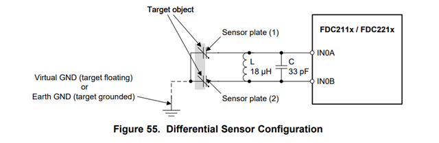
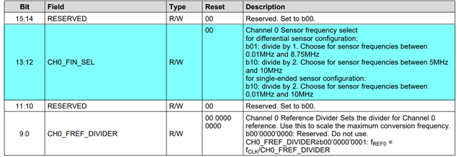
In the differential sensor configuration in Figure 55, one conductive plate is connected to IN0A, and a second conductive plate is connected to IN0B. Together, they form a variable capacitor. When using an single-ended sensor configuration, set CHx_FIN_SEL to b10 (divide by 2).This is explained in the file, but I didn't see how to set it to differential input
就是想问一i下 FDC2214中差分输入怎么输入因为在数据手册中是这样说的In the differential sensor configuration in Figure 55, one conductive plate is connected to IN0A, and a second conductive plate is connected to IN0B. Together, they form a variable capacitor. When using an single-ended sensor configuration, set CHx_FIN_SEL to b10 (divide by 2).