Other Parts Discussed in Thread: DCA1000EVM,
各位工程师好,我近期还购买了一批DCA1000EVM 以及AWR1443BOOST (Rev B)版本用于相关测试。
在拿到板子时,我首先使用了"ti\mmwave_studio_02_01_01_00\mmWaveStudio\Scripts\DataCaptureDemo_xWR.lua"脚本进行测试,同时修改其中的SensorConfig Tag中的Sample Rate从10Msps到62.5Msps以符合相关要求,能够录制到大小符合的adc_data.bin。
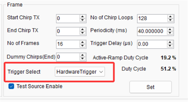
后来因为SAR成像的同步需求,要将板子的模式改为硬件触发模式。
期间查阅了论坛上的相关问题和帖子,都提到了xWR1xxx板子上需要卸除R62电阻以屏蔽DCA1000EVM从LVDS中发出的SYNC_IN信号,或者卸除DCA1000EVM的R120电阻以获得相同效果。(不知我理解的是否准确?如有错误还请指出)
然后在J5的P10重新引入外部的3.3V规定的25ns~1μs的方框脉冲,即SYNC_IN信号进行硬件触发。
但实际操作中,我遇到了一些问题。
首先,我暂未了解SensorConfig Tag中的Software Trigger和Hardware Trigger的工作方式。
我原先理解Software Trigger模式下,DCA1000EVM也会将SYNC_IN信号通过LVDS输入到AWR1443BOOST中,所以我在它在Software Trigger模式能正常工作的前提下,对R62电阻进行了接地操作(即寻找一根接GND的引线接触R62一端),但依然录制了规定大小的adc_data.bin,是否可以理解为Software Trigger模式下,该SYNC_IN信号触发由AWR1443BOOST自主管理,而不是DCA1000EVM通过LVDS控制?
后来,抱有该疑问,我将SensorConfig Tag中的触发方式改为Hardware Tigger,我理解为该模式下应当由DCA1000EVM进行触发操作,但提示告诉我收到的帧数为0,即没有录制任何数据,监控以太网口也没有任何数据传入,我暂未明白该工作情况下发生了什么问题。
mmwave studio采用的2.1.1.0版本。
BSS和MSS版本如下:
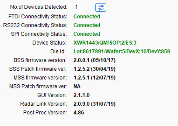
Output日志如下(日志中有提示到 [RadarAPI]: Status: Failed, Error Type: REGULAR ADC MODE NOT SUPPORTED IN 5 MHz PART VARIANT DEVICE,但是最后能录制数据所以我也没有太在意它):
[19:14:01]  [RadarAPI]: ar1.PowerOff()
[19:14:01]  [RadarAPI]: Status: Passed
[19:14:01]  [RadarAPI]: Opening Gpio Control Port()
[19:14:01]  [RadarAPI]: Status: Passed
[19:14:01]  [RadarAPI]: ar1.Disconnect()
[19:14:01]  [RadarAPI]: ar1.Calling_ATE_DisconnectTarget()
[19:14:01]  [RadarAPI]: ar1.Calling_IsConnected()
[19:14:01]  [RadarAPI]: ar1.SaveSettings('C:\Users\99451\AppData\Roaming\RSTD\ar1gui.ini')
[19:14:01]  [RadarAPI]: Opening Board Control Port()
[19:14:01]  [RadarAPI]: Status: Passed
[19:14:02]  [RadarAPI]: ar1.Connect(6,921600,1000)
[19:14:02]  [RadarAPI]: ar1.FullReset()
[19:14:02]  [RadarAPI]: Status: Passed
[19:14:03]  [RadarAPI]: Closing Board Control Port()
[19:14:03]  [RadarAPI]: Status: Passed
[19:14:03]  [RadarAPI]: Closing Gpio Control Port()
[19:14:03]  [RadarAPI]: Status: Passed
[19:14:03]  [RadarAPI]: ar1.SOPControl(2)
[19:14:03]  [RadarAPI]: Status: Passed
[19:14:05]  [RadarAPI]: Warning: Connected with baudrate 115200
[19:14:06]  [RadarAPI]: Warning: Disconnected existing BaudRate
[19:14:06]  [RadarAPI]: Warning: Trying to connect with baudrate 921600
[19:14:08]  [RadarAPI]: ar1.Calling_IsConnected()
[19:14:09]  [RadarAPI]: ar1.SelectChipVersion("AR1243")
[19:14:09]  [RadarAPI]: Status: Passed
[19:14:09]  [RadarAPI]: ar1.SelectChipVersion("XWR1443")
[19:14:09]  [RadarAPI]: Status: Passed
[19:14:09]  Device Status : XWR1443/QM/SOP:2/ES:3
[19:14:09]  [RadarAPI]: ar1.SaveSettings('C:\Users\99451\AppData\Roaming\RSTD\ar1gui.ini')
[19:14:18]  [RadarAPI]: ar1.ReadRegister(0xffffe214, 0, 31)
[19:14:19]  [RadarAPI]: ar1.ReadRegister(0xffffe210, 0, 31)
[19:14:19]  [RadarAPI]: ar1.ReadRegister(0xffffe218, 0, 31)
[19:14:19]  [RadarAPI]: ar1.DownloadBSSFw("C:\\ti\\mmwave_studio_02_01_01_00\\mmWaveStudio\\Scripts\\..\\..\\rf_eval_firmware\\radarss\\xwr12xx_xwr14xx_radarss.bin")
[19:14:19]  [RadarAPI]: Downloading BSS Patch RPRC Binary..
[19:14:21]  [RadarAPI]: ar1.GetBSSFwVersion()
[19:14:21]  [RadarAPI]: BSSFwVersion:(02.00.00.01 (05/10/17))
[19:14:22]  [RadarAPI]: ar1.GetBSSPatchFwVersion()
[19:14:22]  [RadarAPI]: BSSPatchFwVersion:(01.02.05.02 (30/04/19))
[19:14:22]  BSS FW Download Success
[19:14:22]  [RadarAPI]: ar1.DownloadMSSFw("C:\\ti\\mmwave_studio_02_01_01_00\\mmWaveStudio\\Scripts\\..\\..\\rf_eval_firmware\\masterss\\xwr12xx_xwr14xx_masterss.bin")
[19:14:22]  [RadarAPI]: Downloading MSS RPRC Binary..
[19:14:25]  [RadarAPI]: ar1.GetMSSFwVersion()
[19:14:25]  [RadarAPI]: MSSFwVersion:(01.02.05.01 (12/07/19))
[19:14:25]  MSS FW Download Success
[19:14:26]  MSS power up done async event received!
[19:14:26]  [RadarAPI]: ar1.PowerOn(0, 1000, 0, 0)
[19:14:26]  [RadarAPI]: Status: Passed
[19:14:26]  Power On Success
[19:14:26]  [RadarAPI]: ar1.SelectChipVersion("AR1243")
[19:14:26]  [RadarAPI]: Status: Passed
[19:14:26]  [RadarAPI]: ar1.SelectChipVersion("XWR1443")
[19:14:26]  [RadarAPI]: Status: Passed
[19:14:27]  Device Status : XWR1443/QM/SOP:2/ES:3
[19:14:27]  [RadarAPI]: ar1.RfEnable()
[19:14:27]  BSS power up done async event received!
[19:14:27]  [RadarAPI]: Status: Passed
[19:14:27]  [RadarAPI]: ar1.GetMSSFwVersion()
[19:14:27]  [RadarAPI]: MSSFwVersion:(01.02.05.01 (12/07/19))
[19:14:28]  [RadarAPI]: ar1.GetBSSFwVersion()
[19:14:28]  [RadarAPI]: BSSFwVersion:(02.00.00.01 (05/10/17))
[19:14:29]  [RadarAPI]: ar1.GetBSSPatchFwVersion()
[19:14:29]  [RadarAPI]: BSSPatchFwVersion:(01.02.05.02 (30/04/19))
[19:14:29]  RF Enable Success
[19:14:29]  [RadarAPI]: ar1.ChanNAdcConfig(1, 1, 1, 1, 1, 1, 1, 2, 1, 0)
[19:14:29]  [RadarAPI]: Status: Passed
[19:14:29]  ChanNAdcConfig Success
[19:14:29]  [RadarAPI]: ar1.LPModConfig(0, 0)
[19:14:29]  [RadarAPI]: Status: Failed, Error Type: REGULAR ADC MODE NOT SUPPORTED IN 5 MHz PART VARIANT DEVICE
[19:14:29]  Regualar mode Cfg failure
[19:14:29]  [RadarAPI]: ar1.RfInit()
[19:14:29]  RF Init async event received!
[19:14:29]  [RadarAPI]: Time stamp, Temperture: 2315,32; APLL Status, Update: 1, 0; SynthVCO1 Status, Update: 1, 1; SynthVCO2 Status, Update: 1, 1; LODist Status, Update: 1, 1; RxADCDC Status, Update: 1, 1; HPFcutoff Status, Update: 1, 1; LPFcutoff Status, Update: 1, 1; PeakDetector Status, Update: 1, 1; TxPower Status, Update: 1, 1; RxGain Status, Update: 1, 1; TxPhase Status, Update: 0, 0; RxIQMM Status, Update: 1, 1;
[19:14:29]  [RadarAPI]: Status: Passed
[19:14:29]  RfInit Success
[19:14:30]  [RadarAPI]: ar1.DataPathConfig(1, 1, 0)
[19:14:30]  [RadarAPI]: Status: Passed
[19:14:30]  DataPathConfig Success
[19:14:30]  [RadarAPI]: ar1.LvdsClkConfig(1, 1)
[19:14:30]  [RadarAPI]: Status: Passed
[19:14:30]  LvdsClkConfig Success
[19:14:30]  [RadarAPI]: ar1.LVDSLaneConfig(0, 1, 1, 1, 1, 1, 0, 0)
[19:14:30]  [RadarAPI]: Status: Passed
[19:14:30]  LVDSLaneConfig Success
[19:14:30]  [RadarAPI]: ar1.SetTestSource(4, 3, 0, 0, 0, 0, -327, 0, -327, 327, 327, 327, -2.5, 327, 327, 0, 0, 0, 0, -327, 0, -327, 327, 327, 327, -95, 0, 0, 0.5, 0, 1, 0, 1.5, 0, 0, 0, 0, 0, 0, 0)
[19:14:30]  [RadarAPI]: Status: Passed
[19:14:31]  Test Source Configuration Success
[19:14:31]  [RadarAPI]: ar1.ProfileConfig(0, 77, 100, 6, 60, 0, 0, 0, 0, 0, 0, 29.982, 0, 256, 6250, 0, 0, 30)
[19:14:31]  [RadarAPI]: Status: Passed
[19:14:31]  ProfileConfig Success
[19:14:31]  [RadarAPI]: ar1.ChirpConfig(0, 0, 0, 0, 0, 0, 0, 1, 1, 0)
[19:14:31]  [RadarAPI]: Status: Passed
[19:14:31]  ChirpConfig Success
[19:14:31]  [RadarAPI]: ar1.EnableTestSource(1)
[19:14:31]  [RadarAPI]: Status: Passed
[19:14:31]  Enabling Test Source Success
[19:14:31]  Test Source Already Enabled...!!!
[19:14:31]  [RadarAPI]: ar1.EnableTestSource(1)
[19:14:31]  [RadarAPI]: Status: Passed
[19:14:31]  [RadarAPI]: ar1.FrameConfig(0, 0, 16, 128, 40, 0, 0, 2)
[19:14:31]  [RadarAPI]: Status: Passed
[19:14:31]  FrameConfig Success
[19:14:31]  [RadarAPI]: ar1.SelectCaptureDevice("DCA1000")
[19:14:31]  [RadarAPI]: Status: Passed
[19:14:31]  SelectCaptureDevice Success
[19:14:31]  [RadarAPI]: ar1.CaptureCardConfig_EthInit("192.168.33.30", "192.168.33.180", "c:22:38:4e:5a:c", 4096, 4098)
[19:14:31]  [RadarAPI]: Sending fpga command to DCA1000
[19:14:31]  [RadarAPI]:
[19:14:31]  FPGA Configuration command : Success
[19:14:31]  [RadarAPI]: Sending fpga_version command to DCA1000
[19:14:31]  [RadarAPI]:
[19:14:31]
[19:14:31]  FPGA Version : 2.9 [Record]
[19:14:31]
[19:14:31]  CaptureCardConfig_EthInit Success
[19:14:31]  [RadarAPI]: ar1.CaptureCardConfig_Mode(1, 1, 1, 2, 3, 0)
[19:14:31]  [RadarAPI]: Sending fpga command to DCA1000
[19:14:31]  [RadarAPI]:
[19:14:31]  FPGA Configuration command : Success
[19:14:31]  CaptureCardConfig_Mode Success
[19:14:31]  [RadarAPI]: ar1.CaptureCardConfig_PacketDelay(25)
[19:14:31]  [RadarAPI]: Sending fpga command to DCA1000
[19:14:31]  [RadarAPI]:
[19:14:31]  FPGA Configuration command : Success
[19:14:31]  [RadarAPI]: Sending record command to DCA1000
[19:14:31]  [RadarAPI]:
[19:14:31]  Configure Record command : Success
[19:14:31]  CaptureCardConfig_PacketDelay Success
[19:14:31]  [RadarAPI]: ar1.CaptureCardConfig_StartRecord("C:\\ti\\mmwave_studio_02_01_01_00\\mmWaveStudio\\Scripts\\..\\PostProc\\adc_data.bin", 1)
[19:14:31]  [RadarAPI]: Sending start_record command to DCA1000
[19:14:31]  [RadarAPI]: Status: Passed
[19:14:32]  [RadarAPI]: ar1.StartFrame()
[19:14:32]  [RadarAPI]: Status: Passed
[19:14:32]  Frame start async event received!
[19:14:33]  [RadarAPI]: Frame Ended
[19:14:37]  Please wait for a few seconds for matlab post processing .....!!!!
[19:14:37]  [RadarAPI]: ar1.StartMatlabPostProc("C:\\ti\\mmwave_studio_02_01_01_00\\mmWaveStudio\\Scripts\\..\\PostProc\\adc_data.bin")
[19:14:37]  [RadarAPI]: No of files Captured: 0, Total no of frames for each device : 16
[19:14:37]  Error : The number of files captured is zero!
[19:14:47]
[19:14:47]  ***Script completed successfully.***
我使用的lua脚本如下: