Part Number: TMS320F28379D
Other Parts Discussed in Thread: SYSCONFIG
I am working with the CLB module on TMS320F28379D. I am trying to implement a simple timer (counter + FSM as T flip-flop) to toggle a GPIO, using only driverlib functions (clb.h, xbar.h) without SysConfig.
However, I am running into issues:
-
The counter does not seem to generate MATCH1 events (COUNT0_MATCH1 is always 0).
-
The output LUT's FN field cannot be written with 0xAA (only 0xFF works when writing directly to the register).
-
The FSM output does not behave as expected.
I have checked:
-
CLB and EPWM1 clocks are enabled.
-
GLOBAL_EN is set to 0 during configuration and 1 after configuration.
-
Direct register writes (
HWREG) do not solve the issue.
My question is:
Is SysConfig tool mandatory for configuring the CLB?
(Can the CLB be configured without using SysConfig?)
Can the CLB be fully configured using only driverlib functions, or are there some low-level configurations that must be done through SysConfig-generated code?
If it is possible without SysConfig, could you point me to any working example (without SysConfig) or highlight what might be missing in my configuration?
Thank you for your support.
// ============================================================================
// Project 1: CLB Timer to Toggle LED
// ============================================================================
// Function: Use counter + FSM to implement a T flip-flop for automatic LED toggling
// Output: GPIO25 (OUTPUTXBAR2) - available on LaunchPad
// Period: 1 second @ 100MHz = 100,000,000 (EPWM1 clock)
//
// Signal flow:
// System clock ──→ Counter 0 (count up) ──→ MATCH1 event ──→ FSM0 (T flip-flop) ──→ Output
//
// Truth tables:
// 1. FSM_LUT_OUT = S0
// Input order (EXT_IN1, EXT_IN0, S1, S0)
// 16-bit truth table: 0xAAAA
// (EXT_IN1,EXT_IN0,S1,S0) → output = S0
// Example: 0000→0, 0001→1, 0010→0, 0011→1, ...
//
// 2. S0_next = S0 ^ EXT_IN0 (T flip-flop)
// Input order (EXT_IN1, EXT_IN0, S1, S0)
// 16-bit truth table: 0x5A5A
// Example: 0000→0, 0001→1, 0010→1, 0011→0, ...
//
// 3. Output LUT: OUT = IN0 (pass-through)
// 3-input LUT, 8-bit truth table: 0xAA
// Input order (IN2, IN1, IN0): 000→0, 001→1, 010→0, 011→1, ...
// ============================================================================
CLB_disableCLB(CLB1_BASE); // Force GLOBAL_EN = 0
// ------------------------------------------------------------------------
// Step 1: Configure counter input sources
// ------------------------------------------------------------------------
// The counter requires MODE_0 and MODE_1 to control counting
// We want the counter to always count up, so MODE_0=1 (enable), MODE_1=1 (count up)
//
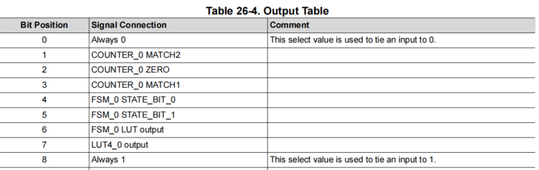
// Select values from Table 26-4(from TRM (Technical Reference Manual) ):
// 0x00 = Always 0
// 0x08 = Always 1
//
// CLB_selectCounterInputs() parameters are 32-bit, format:
// bits 4-0 = select value for unit 0
// bits 9-5 = select value for unit 1
// bits 14-10 = select value for unit 2
// We only use unit 0; set unit 1/2 to 0
uint32_t mode0 = (0x08 << 0) | (0x00 << 5) | (0x00 << 10); // MODE_0 = Always 1
uint32_t mode1 = (0x08 << 0) | (0x00 << 5) | (0x00 << 10); // MODE_1 = Always 1
uint32_t reset = 0x00000000; // RESET = Always 0 (no reset)
uint32_t event = (0x03 << 0) | (0x00 << 5) | (0x00 << 10); // EVENT = MATCH1
CLB_selectCounterInputs(CLB1_BASE, reset, event, mode0, mode1);
// ------------------------------------------------------------------------
// Step 2: Configure counter load and match values
// ------------------------------------------------------------------------
// load: counter starts from 0
// match1: when counter value equals match1, MATCH1 outputs a high pulse
// match2: not used
//
// CLB clock = 100MHz, 1 second timer = 100,000,000 counts
CLB_configCounterLoadMatch(CLB1_BASE, CLB_CTR0,
0x00000000U, // load = 0
50000000U, // match1 = 50000000
0x00000000U); // match2 = 0
// ------------------------------------------------------------------------
// Step 3: Configure counter mode
// ------------------------------------------------------------------------
// COUNT_EVENT_CTRL_0 = 0 (load preset value on EVENT)
CLB_configMiscCtrlModes(CLB1_BASE, 0x00000000);
// ------------------------------------------------------------------------
// Step 4: Configure FSM0 input sources
// ------------------------------------------------------------------------
// FSM0's EXT_IN0 receives the counter's MATCH1 signal (to trigger state toggle)
// Table 26-4: COUNTER_0 MATCH1 = 0x03
uint32_t fsmExternal0 = (0x03 << 0) | (0x00 << 5) | (0x00 << 10); // EXT_IN0 = MATCH1
uint32_t fsmExternal1 = 0x00000000; // EXT_IN1 = Always 0 (not used)
uint32_t fsmExtra0 = 0x00000000; // EXTRA_EXT_IN0 = Always 0 (not used)
uint32_t fsmExtra1 = 0x00000000; // EXTRA_EXT_IN1 = Always 0 (not used)
CLB_selectFSMInputs(CLB1_BASE, fsmExternal0, fsmExternal1, fsmExtra0, fsmExtra1);
// ------------------------------------------------------------------------
// Step 5: Configure FSM LUT function (output logic)
// ------------------------------------------------------------------------
// FSM_LUT_OUT = S0 (directly output current state)
// Truth table calculation (input order: EXT_IN1, EXT_IN0, S1, S0):
// We only care about S0, with EXT_IN1=0, EXT_IN0=any, S1=0
// Output is 0 when S0=0, 1 when S0=1
// 16-bit truth table = 0xAAAA (1010 1010 1010 1010)
CLB_configFSMLUTFunction(CLB1_BASE, 0xAAAA, 0x0000);
// ------------------------------------------------------------------------
// Step 6: Configure FSM next state (T flip-flop)
// ------------------------------------------------------------------------
// S0_next = S0 ^ EXT_IN0 (toggle on each MATCH1 pulse)
// Truth table (EXT_IN0, S0):
// 00→0, 01→1, 10→1, 11→0
// 16-bit truth table = 0x5A5A
CLB_configFSMNextState(CLB1_BASE, 0x5A5A, 0x0000, 0x0000);
// ------------------------------------------------------------------------
// Step 7: Configure output LUT (3-input, for final output)
// ------------------------------------------------------------------------
// outputCfg format (32-bit):
// bits 4-0: IN0 select value
// bits 9-5: IN1 select value
// bits 14-10: IN2 select value
// bits 22-15: FN (8-bit truth table)
//
// We use OUT13 (can connect to Output X-BAR)
// IN0 = FSM_0 LUT output (Table 26-4: 0x06)
// FN = 0xAA (8-bit: 1010 1010) meaning OUT = IN0
uint32_t outputCfg = (0x06 << 0) | (0x00 << 5) | (0x00 << 10) | (0xAA << 15);
// Configure OUT5 (OUTLUT5)
CLB_configOutputLUT(CLB1_BASE, CLB_OUT5, outputCfg);
// Enable OUT13 output
CLB_setOutputMask(CLB1_BASE, CLB_OUTPUT_05, true);
CLB_setOutputMask(CLB1_BASE, CLB_OUTPUT_13, true);
// ------------------------------------------------------------------------
// Step 8: Configure Output X-BAR (route CLB output to GPIO)
// ------------------------------------------------------------------------
// Table 9-4: G3 option 2 = CLB1_OUT13
// Route CLB1_OUT13 to OUTPUTXBAR2 (GPIO25)
XBAR_setOutputMuxConfig(XBAR_OUTPUT2, XBAR_OUT_MUX03_CLB1_OUT5);
XBAR_enableOutputMux(XBAR_OUTPUT2, XBAR_MUX03);
// ------------------------------------------------------------------------
// Step 9: Start CLB
// ------------------------------------------------------------------------
CLB_enableCLB(CLB1_BASE);