

Part Number: LM3481-Q1
Other Parts Discussed in Thread: LM3481
Hello, TI's technical engineer!
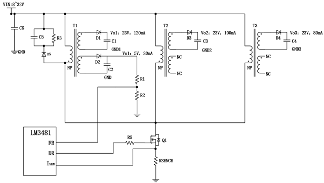
As shown in the figure above, the project uses an LM3481 and a MOSFET to control three transformers for the flyback power output. The 5V winding output from transformer T1 serves as the main feedback, while the remaining output sides VO1, VO2, and VO3 are used to drive three isolated IGBTs and other loads. The parameters of the three transformers (T1、T2 andT3)are exactly the same. My questions are as follows:
Q1:Under normal circumstances, the LM3481 is used to control one MOSFET and one transformer. Now it is used to control three transformers. Is this scheme feasible? Is there a risk of component failure?
Q2:Can the voltage output on the secondary side of the three transformers be controlled around 23V? If not, which transformer output will be out of control? What is the output voltage?
Q3:Due to the inconsistent load of the transformer, the energy stored in the primary inductance of the lightly loaded transformer (T3) cannot be completely consumed by the secondary side. Where is the release path for the remaining energy? Is there a voltage spike or current spike in the release of the remaining energy, and what are the values of the spike voltage or current? Is there a mathematical expression for this?
I look forward to receiving your professional response, thank you.
