Part Number: LAUNCHXL-CC1352R1
#include <stdint.h>
#include <stddef.h>
#include <math.h>
#include <stdio.h>
#include <string.h>
/* 驱动头文件 */
#include <ti/drivers/DAC.h>
#include <ti/drivers/Timer.h>
#include <ti/drivers/GPIO.h>
#include <ti/drivers/UART.h>
/* 驱动配置 */
#include "ti_drivers_config.h"
#define COUNT (128)
#define HALFCOUNT (COUNT/2)
DAC_Handle dacHandle;
UART_Handle uart;
UART_Params uartParams;
uint32_t sintable[COUNT] = {0x80,0x86,0x8c,0x92,0x98,0x9e,0xa5,0xaa,
0xb0,0xb6,0xbc,0xc1,0xc6,0xcb,0xd0,0xd5,
0xda,0xde,0xe2,0xe6,0xea,0xed,0xf0,0xf3,
0xf5,0xf8,0xfa,0xfb,0xfd,0xfe,0xfe,0xff,
0xff,0xff,0xfe,0xfe,0xfd,0xfb,0xfa,0xf8,
0xf5,0xf3,0xf0,0xed,0xea,0xe6,0xe2,0xde,
0xda,0xd5,0xd0,0xcb,0xc6,0xc1,0xbc,0xb6,
0xb0,0xaa,0xa5,0x9e,0x98,0x92,0x8c,0x86,
0x80,0x79,0x73,0x6d,0x67,0x61,0x5a,0x55,
0x4f,0x49,0x43,0x3e,0x39,0x34,0x2f,0x2a,
0x25,0x21,0x1d,0x19,0x15,0x12,0x0f,0x0c,
0x0a,0x07,0x05,0x04,0x02,0x01,0x01,0x00,
0x00,0x00,0x01,0x01,0x02,0x04,0x05,0x07,
0x0a,0x0c,0x0f,0x12,0x15,0x19,0x1d,0x21,
0x25,0x2a,0x2f,0x34,0x39,0x3e,0x43,0x49,
0x4f,0x55,0x5a,0x61,0x67,0x6d,0x73,0x79};
uint16_t sin_count = 0;
uint16_t count = 0;
Timer_Handle timer0;
char str[30];
/**
\brief timerCallback
\note 无特殊说明
\see 无参考
\param 参数myHandle: 定时器句柄
\param 参数status: 定时器状态
\retval None
\warning 无警告
*/
void timerCallback(Timer_Handle myHandle, int_fast16_t status);
/**
\brief get_sintable
\note 无特殊说明
\see 无参考
\param 参数count: 生成样本的数量
\param 参数table: 存储生成样本的数组
\retval None
\warning 无警告
*/
void get_sintable(uint16_t count,uint32_t *table);
/**
\brief mainThread
\note 无特殊说明
\see 无参考
\param 参数arg0: 额外传递的参数
\retval None
\warning 无警告
*/
void *mainThread(void *arg0)
{
Timer_Params params;
DAC_Params dacParams;
Timer_init();
//GPIO_init();
DAC_init();
UART_init();
//GPIO_setConfig(CONFIG_GPIO_0, GPIO_CFG_OUT_STD | GPIO_CFG_OUT_LOW);
//GPIO_write(CONFIG_GPIO_0, CONFIG_GPIO_LED_ON);
UART_Params_init(&uartParams);
uartParams.writeDataMode = UART_DATA_BINARY;
uartParams.readDataMode = UART_DATA_BINARY;
uartParams.readReturnMode = UART_RETURN_FULL;
uartParams.baudRate = 115200;
uart = UART_open(CONFIG_UART_0, &uartParams);
get_sintable(COUNT,sintable);
DAC_Params_init(&dacParams);
dacHandle = DAC_open(CONFIG_DAC_0, &dacParams);
DAC_enable(dacHandle);
Timer_Params_init(¶ms);
params.period = 10000;
params.periodUnits = Timer_PERIOD_US;
params.timerMode = Timer_CONTINUOUS_CALLBACK;
params.timerCallback = timerCallback;
timer0 = Timer_open(CONFIG_TIMER_0, ¶ms);
Timer_start(timer0);
while(1)
{
}
}
void timerCallback(Timer_Handle myHandle, int_fast16_t status)
{
// if(sin_count < COUNT - 1 && sin_count != HALFCOUNT)
// {
// DAC_setCode(dacHandle, sintable[sin_count++]);
//// sprintf(str,"%d\n",sintable[sin_count]);
// }
// else if(sin_count == HALFCOUNT)
// {
// sin_count += 15;
// DAC_setCode(dacHandle, sintable[sin_count++]);
// }
// else
// {
// DAC_setCode(dacHandle, sintable[sin_count]);
//// sprintf(str,"%d\n",sintable[sin_count]);
// sin_count = 15;
// }
// if(sin_count < COUNT - 1)
// {
// DAC_setCode(dacHandle, sintable[sin_count++]);
// }
// else
// {
// DAC_setCode(dacHandle, sintable[sin_count]);
// sin_count = 0;
// }
DAC_setCode(dacHandle, sintable[sin_count]);
sin_count++;
if(sin_count >= COUNT)
{
sin_count = 0;
}
sprintf(str,"%d %d\n", sin_count,sintable[sin_count]);
UART_write(uart, str, strlen(str));
// UART_write(uart, str, strlen(str));
}
void get_sintable(uint16_t count,uint32_t *table)
{
uint16_t i = 0;
for(i = 1;i <= count;i++)
{
double num = (1.0+sin(2.0*M_PI *(1.0*i/(count))))*128;
table[i-1] = num ;
// if(i == HALFCOUNT)
// {
// sprintf(str,"-----------\n");
// UART_write(uart, str, strlen(str));
// }
sprintf(str,"%d\n", table[i]);
UART_write(uart, str, strlen(str));
}
}
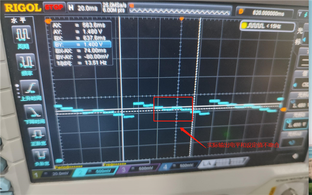
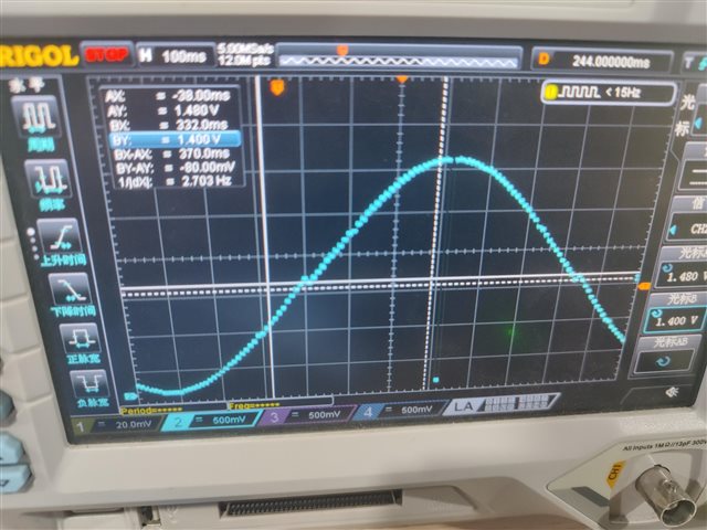
原始代码如上,在示波器上发现正负半周交界处会存在失真,多次优化波表后仍存在此情况,具体如下图:
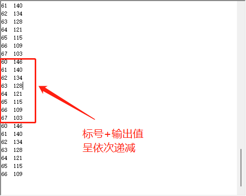
然后逐步排查问题,通过串口打印数据进行调试,发现串口打印数据正常,但单片机实际输出电压却不与设定电压不吻合。
如下: