Part Number: CC1310
尊敬的TI工程师您好:
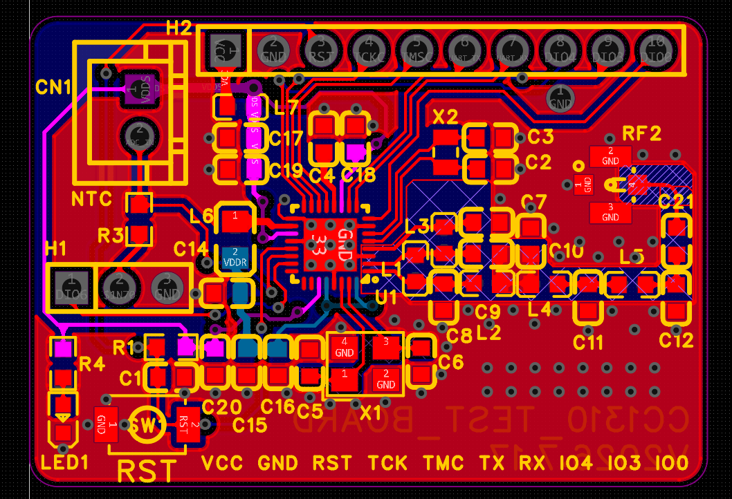
现在我使用CC1310F128RSMR芯片做开发,使用DIO5口作为ADC输入引脚,间隔一定时间唤醒主CPU,在CC1310-MAUNCHXL上得到验证(使用的是DIO23作为ADC输入),在官方提供的rfWsnNode_CC1310例程上进行修改,将未用到的引脚设置为PIN_UNASSIGNED,用到了DIO5,DIO6,DIO4,DIO1,DIO2几个引脚,使用了NVS保存参数到Flash,参数保存位置是0x1C000,共32字节。外部32.768khz无源晶振使用2012贴片无源晶振 32.768kHz ±20ppm 12.5pF负载电容15pf,24Mhz无源晶振使用3225 24Mhz ±10ppm 20pF负载电容22pf,PCB设计图请看图片,使用XDS110烧写程序有的电路板可以烧写有的无法烧写,但能识别到芯片,使用 SmartRF Flash Programmer 2 能读写flash。
有一些电路板可以烧写程序,串口工作正常,但射频无法发送数据,测量32.768khz晶振无波形输出
烧写程序报错信息如下:[ERROR] Cortex_M3_0: Error: (Error -1170 @ 0x0) Unable to access the DAP. Reset the device, and retry the operation. If error persists, confirm configuration, power-cycle the board, and/or try more reliable JTAG settings (e.g. lower TCLK). (Emulation package 21.0.0.3955)
[2026/7/22 下午2:05:42] [ERROR] Cortex_M3_0: Trouble Halting Target CPU: (Error -2064 @ 0x0) Unable to read device status. Reset the device, and retry the operation. If error persists, confirm configuration, power-cycle the board, and/or try more reliable JTAG settings (e.g. lower TCLK). (Emulation package 21.0.0.3955)
PCB设计如下: