If you have a related question, please click the "Ask a related question" button in the top right corner. The newly created question will be automatically linked to this question.
/*
* Copyright (c) 2019, Texas Instruments Incorporated
* All rights reserved.
*
* Redistribution and use in source and binary forms, with or without
* modification, are permitted provided that the following conditions
* are met:
*
* * Redistributions of source code must retain the above copyright
* notice, this list of conditions and the following disclaimer.
*
* * Redistributions in binary form must reproduce the above copyright
* notice, this list of conditions and the following disclaimer in the
* documentation and/or other materials provided with the distribution.
*
* * Neither the name of Texas Instruments Incorporated nor the names of
* its contributors may be used to endorse or promote products derived
* from this software without specific prior written permission.
*
* THIS SOFTWARE IS PROVIDED BY THE COPYRIGHT HOLDERS AND CONTRIBUTORS "AS IS"
* AND ANY EXPRESS OR IMPLIED WARRANTIES, INCLUDING, BUT NOT LIMITED TO,
* THE IMPLIED WARRANTIES OF MERCHANTABILITY AND FITNESS FOR A PARTICULAR
* PURPOSE ARE DISCLAIMED. IN NO EVENT SHALL THE COPYRIGHT OWNER OR
* CONTRIBUTORS BE LIABLE FOR ANY DIRECT, INDIRECT, INCIDENTAL, SPECIAL,
* EXEMPLARY, OR CONSEQUENTIAL DAMAGES (INCLUDING, BUT NOT LIMITED TO,
* PROCUREMENT OF SUBSTITUTE GOODS OR SERVICES; LOSS OF USE, DATA, OR PROFITS;
* OR BUSINESS INTERRUPTION) HOWEVER CAUSED AND ON ANY THEORY OF LIABILITY,
* WHETHER IN CONTRACT, STRICT LIABILITY, OR TORT (INCLUDING NEGLIGENCE OR
* OTHERWISE) ARISING IN ANY WAY OUT OF THE USE OF THIS SOFTWARE,
* EVEN IF ADVISED OF THE POSSIBILITY OF SUCH DAMAGE.
*/
/***** Includes *****/
/* Standard C Libraries */
#include <stdlib.h>
#include <unistd.h>
/* TI Drivers */
#include <ti/drivers/rf/RF.h>
#include <ti/drivers/PIN.h>
#include <ti/drivers/I2C.h>
#include <ti/drivers/pin/PINCC26XX.h>
/* Driverlib Header files */
#include DeviceFamily_constructPath(driverlib/rf_prop_mailbox.h)
/* Board Header files */
#include "Board.h"
#include "CC1310_LAUNCHXL.h"
#include "smartrf_settings/smartrf_settings.h"
#include <ti/drivers/ADCBuf.h>
#include <ti/drivers/adcbuf/ADCBufCC26XX.h>
/***** Defines *****/
/* Do power measurement */
//#define POWER_MEASUREMENT
#define M117_ENABLE 1
/* Packet TX Configuration */
#define PAYLOAD_LENGTH 10
#ifdef POWER_MEASUREMENT
#define PACKET_INTERVAL 5 /* For power measurement set packet interval to 5s */
#else
#define PACKET_INTERVAL 500000 /* Set packet interval to 500000us or 500ms */
#endif
/***** Prototypes *****/
/***** Variable declarations *****/
static RF_Object rfObject;
static RF_Handle rfHandle;
/* Pin driver handle */
static PIN_Handle ledPinHandle;
static PIN_State ledPinState;
static uint8_t packet[PAYLOAD_LENGTH];
static uint16_t seqNumber;
/*
* Application LED pin configuration table:
* - All LEDs board LEDs are off.
*/
PIN_Config pinTable[] =
{
Board_PIN_LED1 | PIN_GPIO_OUTPUT_EN | PIN_GPIO_LOW | PIN_PUSHPULL | PIN_DRVSTR_MAX,
#ifdef POWER_MEASUREMENT
#if defined(Board_CC1350_LAUNCHXL)
Board_DIO30_SWPWR | PIN_GPIO_OUTPUT_EN | PIN_GPIO_HIGH | PIN_PUSHPULL | PIN_DRVSTR_MAX,
#endif
#endif
PIN_TERMINATE
};
/***** Function definitions *****/
extern void iic_map(uint8_t sclPin,uint8_t sdaPin);
void *mainThread(void *arg0)
{
#if M117_ENABLE
// One-time init of I2C driver
I2C_init();
// initialize optional I2C bus parameters
I2C_Params params;
I2C_Params_init(¶ms);
params.bitRate = I2C_100kHz;
params.transferMode = I2C_MODE_BLOCKING;
// Open I2C bus for usage
//I2C_Handle i2cHandle = I2C_open(0, ¶ms);
// Initialize slave address of transaction
I2C_Transaction transaction = {0};
transaction.slaveAddress = 0x44;
I2C_Handle i2cHandle;
I2C_Handle i2cHandle2;
i2cHandle = I2C_open(0, ¶ms);
#endif
RF_Params rfParams;
RF_Params_init(&rfParams);
/* Open LED pins */
ledPinHandle = PIN_open(&ledPinState, pinTable);
if (ledPinHandle == NULL)
{
while(1);
}
#ifdef POWER_MEASUREMENT
#if defined(Board_CC1350_LAUNCHXL)
/* Route out PA active pin to Board_DIO30_SWPWR */
PINCC26XX_setMux(ledPinHandle, Board_DIO30_SWPWR, PINCC26XX_MUX_RFC_GPO1);
#endif
#endif
RF_cmdPropTx.pktLen = PAYLOAD_LENGTH;
RF_cmdPropTx.pPkt = packet;
RF_cmdPropTx.startTrigger.triggerType = TRIG_NOW;
/* Request access to the radio */
#if defined(DeviceFamily_CC26X0R2)
rfHandle = RF_open(&rfObject, &RF_prop, (RF_RadioSetup*)&RF_cmdPropRadioSetup, &rfParams);
#else
rfHandle = RF_open(&rfObject, &RF_prop, (RF_RadioSetup*)&RF_cmdPropRadioDivSetup, &rfParams);
#endif// DeviceFamily_CC26X0R2
/* Set the frequency */
RF_postCmd(rfHandle, (RF_Op*)&RF_cmdFs, RF_PriorityNormal, NULL, 0);
while(1)
{
#if M117_ENABLE
//i2cHandle = I2C_open(0, ¶ms);
uint8_t iic_write_data[] = {0xCC,0x44};
uint8_t iic_read_data[3];
// Write to I2C slave device
transaction.writeBuf = iic_write_data;
transaction.writeCount = sizeof(iic_write_data);
transaction.readCount = 0;
I2C_transfer(i2cHandle, &transaction);
//I2C_close(i2cHandle);
usleep(10000);
//i2cHandle = I2C_open(0, ¶ms);
// Read from I2C slave device
transaction.readBuf = iic_read_data;
transaction.readCount = sizeof(iic_read_data);
transaction.writeCount = 0;
I2C_transfer(i2cHandle, &transaction);
packet[2] = iic_read_data[0];
packet[3] = iic_read_data[1];
packet[4] = iic_read_data[2];
//I2C_close(i2cHandle);
//usleep(5000);//屏蔽这行会死机
//I2C_cancel(i2cHandle);
#if 1
//iic_map(IOID_20,IOID_21);
//i2cHandle = I2C_open(0, ¶ms);
// Write to I2C slave device
transaction.writeBuf = iic_write_data;
transaction.writeCount = sizeof(iic_write_data);
transaction.readCount = 0;
I2C_transfer(i2cHandle, &transaction);
//I2C_close(i2cHandle);
usleep(10000);
//i2cHandle = I2C_open(0, ¶ms);
// Read from I2C slave device
transaction.readBuf = iic_read_data;
transaction.readCount = sizeof(iic_read_data);
transaction.writeCount = 0;
I2C_transfer(i2cHandle, &transaction);
packet[2] = iic_read_data[0];
packet[3] = iic_read_data[1];
packet[4] = iic_read_data[2];
//I2C_close(i2cHandle);
//iic_map(IOID_4,IOID_5);
#endif
#if 0
//iiC_map(IOID_20,IOID_21);
i2cHandle2 = I2C_open(1, ¶ms);
// Write to I2C slave device
transaction.writeBuf = iic_write_data;
transaction.writeCount = sizeof(iic_write_data);
transaction.readCount = 0;
I2C_transfer(i2cHandle2, &transaction);
//I2C_close(i2cHandle2);
usleep(10000);
//i2cHandle2 = I2C_open(0, ¶ms);
// Read from I2C slave device
transaction.readBuf = iic_read_data;
transaction.readCount = sizeof(iic_read_data);
transaction.writeCount = 0;
I2C_transfer(i2cHandle2, &transaction);
packet[2] = iic_read_data[0];
packet[3] = iic_read_data[1];
packet[4] = iic_read_data[2];
I2C_close(i2cHandle2);
//iiC_map(IOID_4,IOID_5);
#endif
#endif
/* Create packet with incrementing sequence number and random payload */
packet[0] = (uint8_t)(seqNumber >> 8);
packet[1] = (uint8_t)(seqNumber++);
//uint8_t i;
//for (i = 2; i < PAYLOAD_LENGTH; i++)
//{
// packet[i] = rand();
//}
packet[2] = 2;
packet[3] = 3;
packet[4] = 4;
/* Send packet */
RF_EventMask terminationReason = RF_runCmd(rfHandle, (RF_Op*)&RF_cmdPropTx,
RF_PriorityNormal, NULL, 0);
switch(terminationReason)
{
case RF_EventLastCmdDone:
// A stand-alone radio operation command or the last radio
// operation command in a chain finished.
break;
case RF_EventCmdCancelled:
// Command cancelled before it was started; it can be caused
// by RF_cancelCmd() or RF_flushCmd().
break;
case RF_EventCmdAborted:
// Abrupt command termination caused by RF_cancelCmd() or
// RF_flushCmd().
break;
case RF_EventCmdStopped:
// Graceful command termination caused by RF_cancelCmd() or
// RF_flushCmd().
break;
default:
// Uncaught error event
while(1);
}
uint32_t cmdStatus = ((volatile RF_Op*)&RF_cmdPropTx)->status;
switch(cmdStatus)
{
case PROP_DONE_OK:
// Packet transmitted successfully
break;
case PROP_DONE_STOPPED:
// received CMD_STOP while transmitting packet and finished
// transmitting packet
break;
case PROP_DONE_ABORT:
// Received CMD_ABORT while transmitting packet
break;
case PROP_ERROR_PAR:
// Observed illegal parameter
break;
case PROP_ERROR_NO_SETUP:
// Command sent without setting up the radio in a supported
// mode using CMD_PROP_RADIO_SETUP or CMD_RADIO_SETUP
break;
case PROP_ERROR_NO_FS:
// Command sent without the synthesizer being programmed
break;
case PROP_ERROR_TXUNF:
// TX underflow observed during operation
break;
default:
// Uncaught error event - these could come from the
// pool of states defined in rf_mailbox.h
while(1);
}
#ifndef POWER_MEASUREMENT
PIN_setOutputValue(ledPinHandle, Board_PIN_LED1,!PIN_getOutputValue(Board_PIN_LED1));
#endif
/* Power down the radio */
RF_yield(rfHandle);
#ifdef POWER_MEASUREMENT
/* Sleep for PACKET_INTERVAL s */
sleep(PACKET_INTERVAL);
#else
/* Sleep for PACKET_INTERVAL us */
usleep(PACKET_INTERVAL);
#endif
}
}


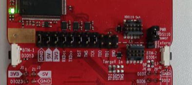
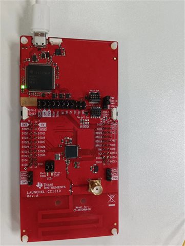 这是我测试的主板