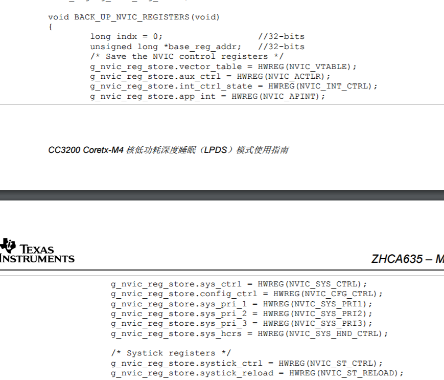
请教工程师们, cc3200连接一个读卡芯片,每20秒会产生1次外部中断,如果寻到卡立刻就产生外部中断。此场景用那种睡眠模式的比较合适,目前采用LPDS模式参照手册移植发现 “Back_up_NVIC_register(); // 保存一般处理器寄存器” 里面很多地址不知道填什么。
This thread has been locked.
If you have a related question, please click the "Ask a related question" button in the top right corner. The newly created question will be automatically linked to this question.
可以直接使用LPDS模式,其实进入到低功耗后的这些寄存器可以不用关系,在LPDS模式下RAM数据保持,如果通过中断后需要记录数据可以写入到片外的SPI Flash中
关于低功耗的操作可以参考如下笔记
//****************************************************************************
//
//! Enter the HIBernate mode configuring the wakeup timer
//!
//! \param none
//!
//! This function
//! 1. Sets up the wakeup RTC timer
//! 2. Enables the RTC
//! 3. Enters into HIBernate
//!
//! \return None.
//
//****************************************************************************
void EnterHIBernate()
{
#define SLOW_CLK_FREQ (32*1024)
//
// Configure the HIB module RTC wake time
//
MAP_PRCMHibernateIntervalSet(5 * SLOW_CLK_FREQ);
//
// Enable the HIB RTC
//
// MAP_PRCMHibernateWakeupSourceEnable(PRCM_HIB_SLOW_CLK_CTR);
//------------------------------------------------------------Hib模式下增加GPIO唤醒---------------------------------------------------------------
// PRCMHibernateWakeupSourceEnable入口参数
// PRCM_HIB_SLOW_CLK_CTR -PRCM_HIB_GPIO2 -PRCM_HIB_GPIO4 -PRCM_HIB_GPIO13 -PRCM_HIB_GPIO17 -PRCM_HIB_GPIO11 -PRCM_HIB_GPIO24 -PRCM_HIB_GPIO26
PRCMHibernateWakeupSourceEnable(PRCM_HIB_GPIO13);
PRCMHibernateWakeUpGPIOSelect(PRCM_HIB_GPIO13,PRCM_HIB_FALL_EDGE); //按键按下去产生上升沿,松开后产生下降沿!注意入口参数的顺序!!!
//------------------------------------------------------------------------------------------------------------------------------------------------
// DBG_PRINT("HIB: Entering HIBernate...\n\r");
UART_PRINT("Entering HIB\n\r");
MAP_UtilsDelay(80000);
//
// powering down SPI Flash to save power
//
Utils_SpiFlashDeepPowerDown();
//
// Enter HIBernate mode
//
MAP_PRCMHibernateEnter();
}
//****************************************************************************
// MAIN FUNCTION
//****************************************************************************
int main(void)
{
long lRetVal;
char cCmdBuff[20];
signed char cCmd = APP_SLEEP; //并非初始化为进入睡眠模式
SlSockAddrIn_t sAddr;
SlSockAddrIn_t sLocalAddr;
SlSockAddrIn_t sBrdAddr;
int iCounter;
int iAddrSize;
int iSockID;
int iStatus;
long lLoopCount = 0;
short sTestBufLen;
struct SlTimeval_t timeVal;
//
// Board Initialization
//
BoardInit();
//
// uDMA Initialization
//
UDMAInit();
//
// Configure the pinmux settings for the peripherals exercised
// Note: pinmux has been modified after the output from pin mux tools
// to enable sleep clk for the peripherals exercised
//
PinMuxConfig();
//
// Initialize the platform
//
platform_init(); //低功耗IO漏电流等处理
//
// Initialise the UART terminal
//
InitTerm();
//
// Display banner
//
DisplayBanner();
//
// starting the simplelink
//
// lRetVal = sl_Start(0, 0, 0);
lRetVal = sl_Start(NULL, NULL, NULL); //运行到这就无法调试了 Warning: **ERROR**: Unable to start execution 0x00000001
if (lRetVal < 0)
{
UART_PRINT("Failed to start the device \n\r");
LOOP_FOREVER();
}
//-------------------------------------------------测试--------------------------------------
if (APconnect==1)
{
//
// Swtich to STA mode if device is not
//
SwitchToStaMode(lRetVal);
//
// set connection policy
//
sl_WlanPolicySet(SL_POLICY_CONNECTION,SL_CONNECTION_POLICY(0, 0, 0, 0, 0), NULL, 0);
//
// Set the power management policy of NWP
// 并非通过下面方法设置NWP的低功耗模式!这只是nwp工作的模式!
lRetVal = sl_WlanPolicySet(SL_POLICY_PM, SL_NORMAL_POLICY, NULL, 0); //注意,设置NWP的电源模式,在nwp programming中4.6.1 Power Policy详细介绍
//Normal (Default) – Features the best tradeoff between traffic delivery time and power performance.
UART_PRINT("Trying to Connect to AP: %s ...\r\n",SSID_NAME);
//---------------------------------------------------连接AP-----------------------------------------------------
//备注:记不清在哪个文档中说明是能DHCP会增加电流消耗?
//Connecting to WLAN AP
//
lRetVal = WlanConnect();
if(lRetVal < 0)
{
UART_PRINT("Failed to establish connection w/ an AP \n\r");
LOOP_FOREVER();
}
//---------------------------------------------------------------------------------------------------------------
// filling the buffer
for (iCounter=0 ; iCounter<BUF_SIZE ; iCounter++)
{
g_cBsdBuf[iCounter] = (char)(iCounter % 10);
}
//---------------------------------------------------建立UDP的服务器-----------------------------------------------------
sTestBufLen = BUF_SIZE;
//filling the UDP server socket address
sLocalAddr.sin_family = SL_AF_INET;
sLocalAddr.sin_port = sl_Htons((unsigned short)PORT_NUM); //本地UDP的端口号
sLocalAddr.sin_addr.s_addr = 0;
//filling the UDP server socket address
sBrdAddr.sin_family = SL_AF_INET;
sBrdAddr.sin_port = sl_Htons((unsigned short)PORT_NUM); //目的UDP的端口号
sBrdAddr.sin_addr.s_addr = sl_Htonl((unsigned int)g_ulDestinationIp);
iAddrSize = sizeof(SlSockAddrIn_t);
// creating a UDP socket
iSockID = sl_Socket(SL_AF_INET,SL_SOCK_DGRAM, 0);
//------------------------------------------设置阻塞模式----------------------------------------
/* setting time out for socket recv */
timeVal.tv_sec = 5; // Seconds
timeVal.tv_usec = 0; // Microseconds. 10000 microseconds resolution
sl_SetSockOpt(iSockID,SL_SOL_SOCKET,SL_SO_RCVTIMEO, (_u8 *)&timeVal, sizeof(timeVal)); //网络接收超时检查打开
//----------------------------------------------------------------------------------------------
// binding the UDP socket to the UDP server address
iStatus = sl_Bind(iSockID, (SlSockAddr_t *)&sLocalAddr, iAddrSize);
if( iStatus < 0 )
{
// error
sl_Close(iSockID);
ASSERT_ON_ERROR(iStatus);
}
//-------------------------------------------------------------------------------------------------------------------------
}
//--------------------------------------------------------------------------
//
// setting Apps power policy
//
// lp3p0_setup_power_policy(POWER_POLICY_STANDBY); //M4-core 进入LPDS 模式 一定把该模式下的唤醒源打开!
// lp3p0_setup_power_policy(POWER_POLICY_HIBERNATE); //M4-core 进入Hib 模式 不再使用!!!!!
UART_PRINT("enter one of the following command:\n\r");
UART_PRINT("sleep - for putting the system into LPDS mode\n\r");
UART_PRINT(" GPIO 13 and timer(5 sec) are the wk source configured\n\r");
UART_PRINT("recv - for receiving 1000 UDP packets\n\r");
UART_PRINT("send - for broadcasting 1000 UDP packets\n\r");
do{
UART_PRINT("cmd#");
//
// get cmd over UART
//
// GetCmd(cCmdBuff, 20); //阻塞CPU运行
//
// parse the command
//
// ParseCmd(cCmdBuff, &cCmd);
// if(cCmd == APP_SLEEP)
if(LPDS==1)
{
//
// set timer and gpio as wake src
//
// set_rtc_as_wk_src(WK_LPDS, LPDS_DUR_SEC, false); //测试LPDS功耗,不使用定时器唤醒,仅使用GPIO唤醒!
// set_gpio_as_wk_src(WK_LPDS, GPIO_SRC_WKUP, PRCM_LPDS_FALL_EDGE);
//------------------------------------------------------------------注意!!---------------------------------------------------------------------------------------------
// set_gpio_as_wk_src(WK_HIB, GPIO_SRC_WKUP, PRCM_LPDS_FALL_EDGE); //必须设置进入Hib模式下的中断唤醒源,
//注意在sl_Stop(10)之前不要启动该语句,否则NWP在sl_Stop(10)之后就自动进入了Hib模式但是唤醒源并没设置OK,直接屏蔽该语句,用EnterHIBernate();即可
//-----------------------------------------------------------------------------------------------------------------------------------------------------------------------
//M4-LPDS+NWP-hib(带UART跳线帽RX/TX=3.3V)=10.6uA 拔掉跳线帽(CC3200-RX/TX=0.1V)=14.5uA
UART_PRINT("M4-LPDS+NWP-hib"); //将CC3200-RX引脚接到GND/VCC=3.3V电流下降到10.65uA;CC3200-TX引脚接到GND/VCC=3.3V电流不发生变化.
/* close socket & stop device */ //Tip:CC3200启动过程中电流在几十mA,但是进入LPDS/Hib模式后电流在uA级别,此时电流档位精度不够,
//此时快速将电流mA档位切换到uA档位,虽然此时J12已经断开,但是注意到J12后面有两个100uF电容在给
//CC3200供电,因此切换完成后电流再补充到电容两端及CC3200电流消耗!
//D5/D6 ON problem.J2 and J3 are shorted by default, so the GPIO 10 and GPIO 11 are pulled up to VCC.
//但是拔掉J2/J3后 LED不亮了但是功耗也没有降低,依然是10.64uA~10.65uA
//注意LPDS中sl_Stop(10)是可以向下运行的,但是改为Hib模式时,根本就没有向下运行!
// sl_Close(iSockID); // 关不关闭socket对功耗没有影响,NWP已经停止工作了,socket自然也就关闭了
// sl_Stop(10);
UART_PRINT("Test\n\r"); // 改为sl_Stop(10)/sl_Stop(1)均可进入此低功耗模式;M4-LPDS+NWP-hib后正常229uA电流
// M4-hib+NWP-hib模式下sl_Stop(10)/sl_Stop(1)/sl_Stop(0)均可进入低功耗模式电流消耗为10uA~14uA左右
// MAP_UtilsDelay(80000); // 延时0.5s让串口的数据打印出来后,M4核再进入低功耗模式.
//
// powering down SPI Flash to save power
//
// Utils_SpiFlashDeepPowerDown(); //在M4-hib+NWP-hib模式下功耗没有降低!但在M4-LPDS+NWP-hib模式下打开SPI Flash低功耗后测得220uA 关闭该语句为229uA
// cc_idle_task_pm(); //LPDS模式用这个可以但是Hib模式不要用,将C:\ti\CC3200SDK_1.1.0\cc3200-sdk\middleware\framework\pm中cc_pm.c添加到工程中查看函数原型!
//-------------------------------------------------------------------------------------
// Stop the NWP driver
// lRetVal = Network_IF_DeInitDriver(); !
// if(lRetVal < 0)
// {
// UART_PRINT("Failed to stop SimpleLink Device\n\r");
// LOOP_FOREVER();
// }
//During Hib mode the entire SOC loses its state, including the MCU subsystem, the NWP subsystem
EnterHIBernate(); //Hib模式用这个进入低功耗,测试屏蔽掉sl_stop(10)即打开NWP连接AP情况下让M4进入Hib模式,测得功耗为10.65uA,与执行sl_stop(10)功耗一致!
//注意Hib模式下测试的电流消耗包括CC3200+SPI_Flash的功耗,而Datasheet上4uA是不包括SPI_Flash的功耗哦
//-------------------------------------------------------------------------------------
UART_PRINT("M4-Active+NWP-hib\n\r"); //测试程序从LPDS唤醒后从哪开始运行---此处!
}
else if(cCmd == APP_RECV)
{
lLoopCount = 0;
/// waits for 1000 packets from a UDP client
while (lLoopCount < g_ulPacketCount)
{
iStatus = sl_RecvFrom(iSockID, g_cBsdBuf, sTestBufLen, 0,( SlSockAddr_t *)&sAddr, (SlSocklen_t*)&iAddrSize );
if( iStatus < 0 )
{
//error
break;
}
lLoopCount++;
}
UART_PRINT("Recieved %u packets successfully \n\r",lLoopCount);
if(lLoopCount != g_ulPacketCount)
{
if(iStatus == SL_EAGAIN)
{
UART_PRINT("timed out\n\r");
}
else
{
UART_PRINT("recv error: %d\n\r", iStatus);
}
}
}
else if(cCmd == APP_SEND)
{
lLoopCount = 0;
// sending 1000 packets to the UDP server
while (lLoopCount < g_ulPacketCount)
{
// sending packet
iStatus = sl_SendTo(iSockID, g_cBsdBuf, sTestBufLen, 0,(SlSockAddr_t *)&sBrdAddr, iAddrSize);
if( iStatus <= 0 )
{
// error
UART_PRINT("send error\n\r");
break;
}
lLoopCount++;
}
UART_PRINT("Sent %u packets successfully\n\r",lLoopCount);
}
}while(FOREVER);
}