

从开发板的SDK中复制相关的文件到自己创建的项目文件中,方便学习和使用。从点亮一个LED灯开始。
一、创建项目文件
1.1、官网获取SDK:SDK
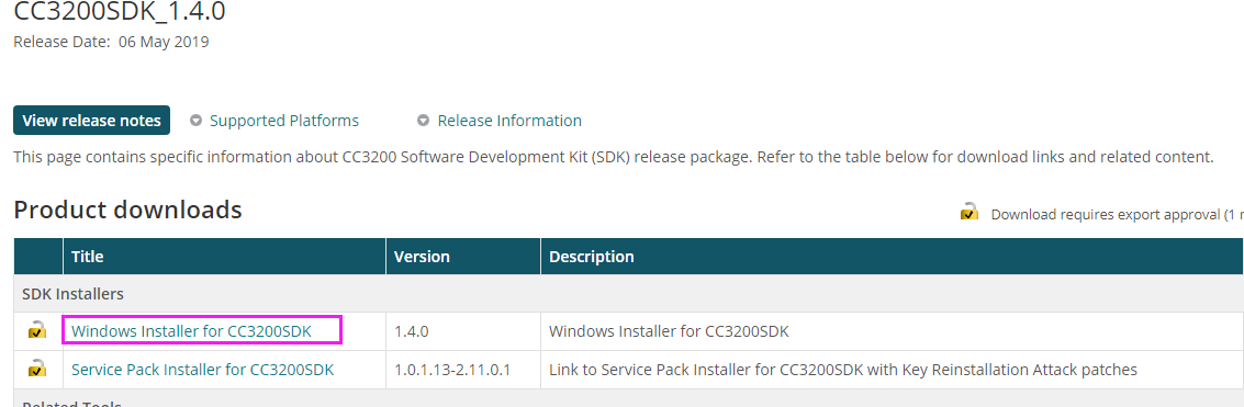
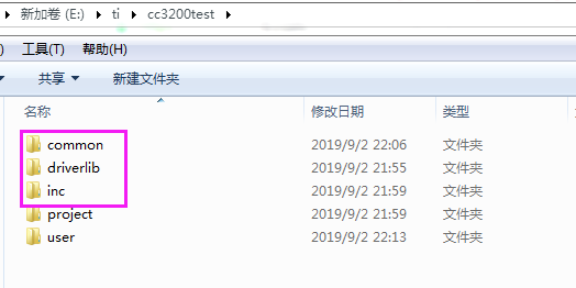
1.2、将SDK文件中的下面文件复制到我创建的项目文件中
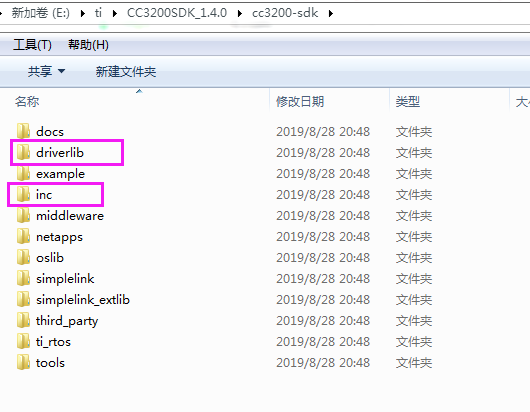
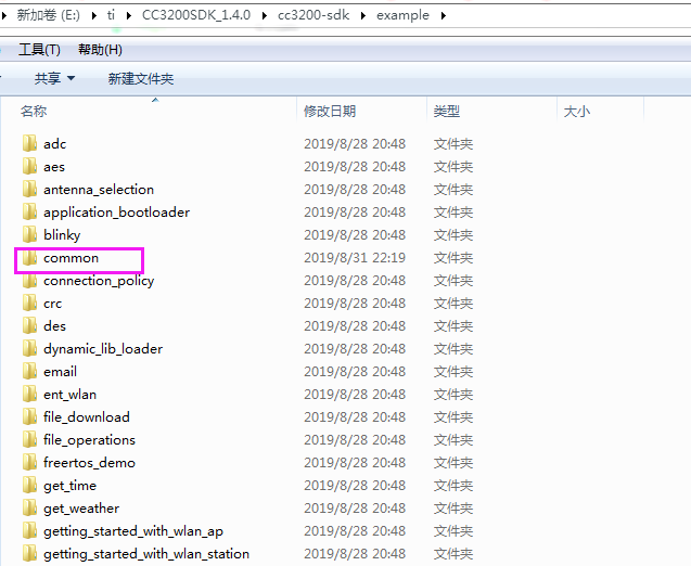
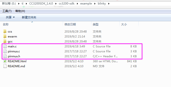
1.3、下面是我创建的项目文件夹
1.4、下面是创建的工程项目。
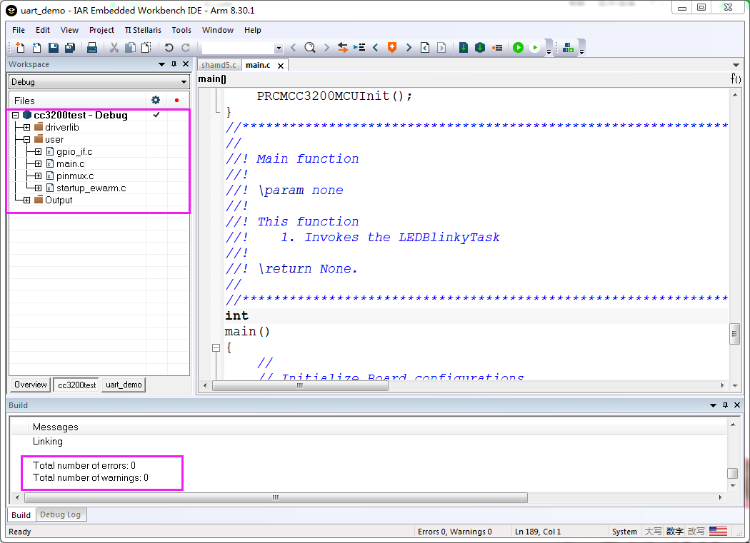
编译工程没有错误。
二、LED部分代码
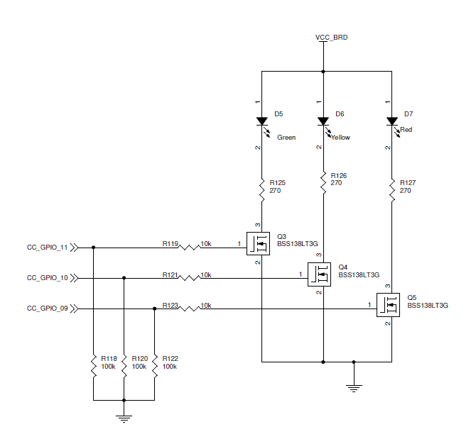
2.1、LED硬件电路
2.2、GPIO驱动LED部分的代码
#include <stdio.h>

// Driverlib includes
#include "hw_types.h"
#include "hw_ints.h"
#include "hw_memmap.h"
#include "hw_common_reg.h"
#include "interrupt.h"
#include "hw_apps_rcm.h"
#include "prcm.h"
#include "rom.h"
#include "rom_map.h"
#include "prcm.h"
#include "gpio.h"
#include "utils.h"

// Common interface includes
#include "gpio_if.h"

#include "pinmux.h"

#define APPLICATION_VERSION     "1.4.0"

//*****************************************************************************
//                 GLOBAL VARIABLES -- Start
//*****************************************************************************
#if defined(ccs)
extern void (* const g_pfnVectors[])(void);
#endif
#if defined(ewarm)
extern uVectorEntry __vector_table;
#endif
//*****************************************************************************
//                 GLOBAL VARIABLES -- End
//*****************************************************************************


//*****************************************************************************
//                      LOCAL FUNCTION PROTOTYPES
//*****************************************************************************
void LEDBlinkyRoutine();
static void BoardInit(void);

//*****************************************************************************
//                      LOCAL FUNCTION DEFINITIONS
//*****************************************************************************

//*****************************************************************************
//
//! Configures the pins as GPIOs and peroidically toggles the lines
//!
//! \param None
//!
//! This function
//!    1. Configures 3 lines connected to LEDs as GPIO
//!    2. Sets up the GPIO pins as output
//!    3. Periodically toggles each LED one by one by toggling the GPIO line
//!
//! \return None
//
//*****************************************************************************
void LEDBlinkyRoutine()
{
    //
    // Toggle the lines initially to turn off the LEDs.
    // The values driven are as required by the LEDs on the LP.
    //
    GPIO_IF_LedOff(MCU_ALL_LED_IND);
    while(1)
    {
        //
        // Alternately toggle hi-low each of the GPIOs
        // to switch the corresponding LED on/off.
        //
        MAP_UtilsDelay(8000000);
        GPIO_IF_LedOn(MCU_RED_LED_GPIO);
        MAP_UtilsDelay(8000000);
        GPIO_IF_LedOff(MCU_RED_LED_GPIO);
        MAP_UtilsDelay(8000000);
        GPIO_IF_LedOn(MCU_ORANGE_LED_GPIO);
        MAP_UtilsDelay(8000000);
        GPIO_IF_LedOff(MCU_ORANGE_LED_GPIO);
        MAP_UtilsDelay(8000000);
        GPIO_IF_LedOn(MCU_GREEN_LED_GPIO);
        MAP_UtilsDelay(8000000);
        GPIO_IF_LedOff(MCU_GREEN_LED_GPIO);
    }

}
//*****************************************************************************
//
//! Board Initialization & Configuration
//!
//! \param  None
//!
//! \return None
//
//*****************************************************************************
static void
BoardInit(void)
{
/* In case of TI-RTOS vector table is initialize by OS itself */
#ifndef USE_TIRTOS
    //
    // Set vector table base
    //
#if defined(ccs)
    MAP_IntVTableBaseSet((unsigned long)&g_pfnVectors[0]);
#endif
#if defined(ewarm)
    MAP_IntVTableBaseSet((unsigned long)&__vector_table);
#endif
#endif

    //
    // Enable Processor
    //
    MAP_IntMasterEnable();
    MAP_IntEnable(FAULT_SYSTICK);

    PRCMCC3200MCUInit();
}
//****************************************************************************
//
//! Main function
//!
//! \param none
//!
//! This function
//!    1. Invokes the LEDBlinkyTask
//!
//! \return None.
//
//****************************************************************************
int
main()
{
    //
    // Initialize Board configurations
    //
    BoardInit();

    //
    // Power on the corresponding GPIO port B for 9,10,11.
    // Set up the GPIO lines to mode 0 (GPIO)
    //
    PinMuxConfig();
    GPIO_IF_LedConfigure(LED1|LED2|LED3);

    GPIO_IF_LedOff(MCU_ALL_LED_IND);

    //
    // Start the LEDBlinkyRoutine
    //
    LEDBlinkyRoutine();
    return 0;
}
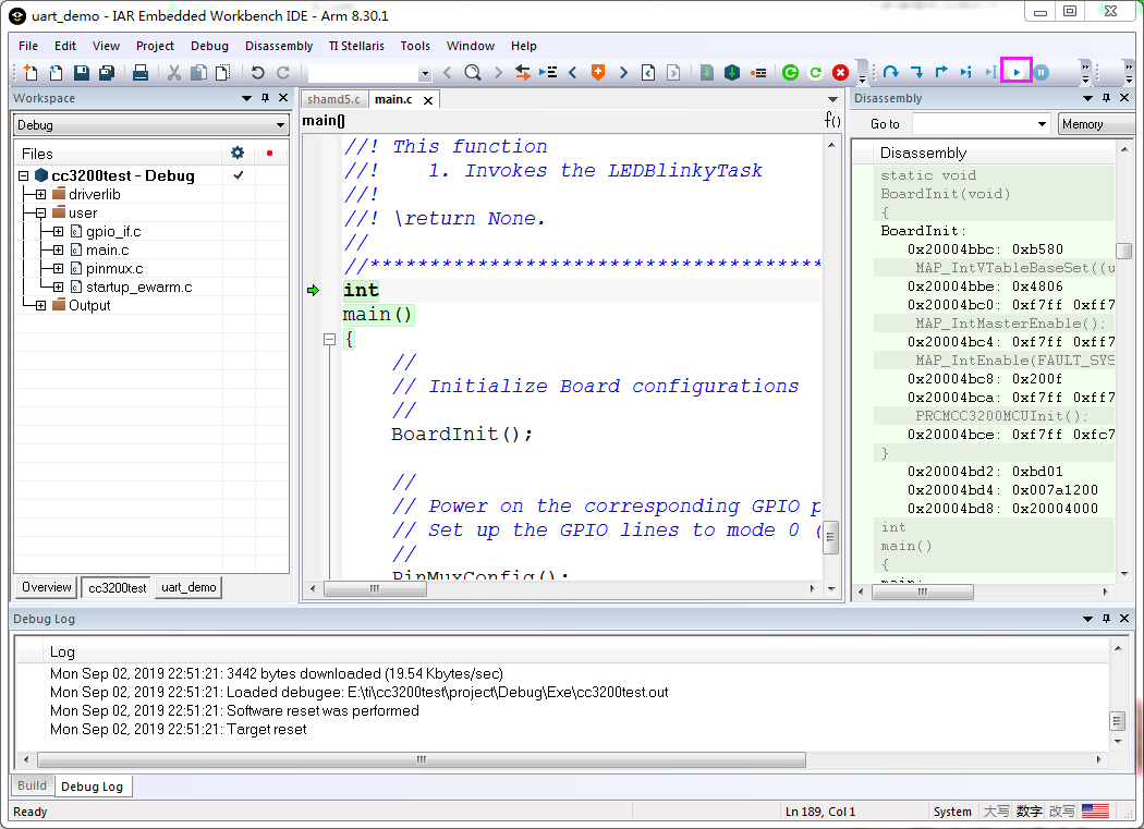
三、仿真程序
五、执行结果
D5,D6,D7 红、绿、蓝LED灯交替点亮,创建的项目完成,程序可以运行。
