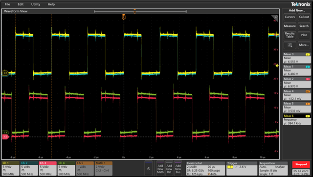
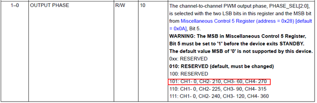
Hello, when we set to "101", we found the current consumption increase(300mA) compare to the default setting, and TAS6424E itself become very hot, what's the reason? thanks!
Hello, when we set to "101", we found the current consumption increase(300mA) compare to the default setting, and TAS6424E itself become very hot, what's the reason? thanks!