TLV320AIC3109-Q1: WS clock line error

Part Number: TLV320AIC3109-Q1

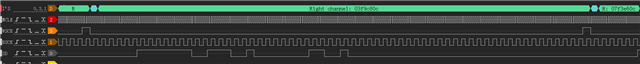
I used STM32L431 as the master to receive audio signals from TLV320. The test found that the trend of the data is right, as the input becomes larger, the output also becomes larger. But the amplitude of the signal seems to be wrong, and the duty cycle of WCLK is not 50%, but 1 bit high and 63 bits low. My configuration is I2S mode, 8K sampling, 32 bits, why does this happen and how can I troubleshoar it?tlv320aic3109-q1.pdf

  • this is my register configuration. 

    /* Page select register */
    #define AIC3X_PAGE_SELECT       0
    /* Software reset register */
    #define AIC3X_RESET         1
    /* Codec Sample rate select register */
    #define AIC3X_SAMPLE_RATE_SEL_REG   2
    /* PLL progrramming register A */
    #define AIC3X_PLL_PROGA_REG     3
    /* PLL progrramming register B */
    #define AIC3X_PLL_PROGB_REG     4
    /* PLL progrramming register C */
    #define AIC3X_PLL_PROGC_REG     5
    /* PLL progrramming register D */
    #define AIC3X_PLL_PROGD_REG     6
    /* Codec datapath setup register */
    #define AIC3X_CODEC_DATAPATH_REG    7
    /* Audio serial data interface control register A */
    #define AIC3X_ASD_INTF_CTRLA        8
    /* Audio serial data interface control register B */
    #define AIC3X_ASD_INTF_CTRLB        9
    /* Audio serial data interface control register C */
    #define AIC3X_ASD_INTF_CTRLC        10
    /* Audio overflow status and PLL R value programming register */
    #define AIC3X_OVRF_STATUS_AND_PLLR_REG  11
    /* Audio codec digital filter control register */
    #define AIC3X_CODEC_DFILT_CTRL      12
    /* Headset/button press detection register */
    #define AIC3X_HEADSET_DETECT_CTRL_A 13
    #define AIC3X_HEADSET_DETECT_CTRL_B 14
    /* ADC PGA Gain control registers */
    #define LADC_VOL            15
    #define RADC_VOL            16
    /* MIC3 control registers */
    #define MIC3LR_2_LADC_CTRL      17
    #define MIC3LR_2_RADC_CTRL      18
    /* Line1 Input control registers */
    #define LINE1L_2_LADC_CTRL      19
    #define LINE1R_2_LADC_CTRL      21
    #define LINE1R_2_RADC_CTRL      22
    #define LINE1L_2_RADC_CTRL      24
    /* Line2 Input control registers */
    #define LINE2L_2_LADC_CTRL      20
    #define LINE2R_2_RADC_CTRL      23
    /* MICBIAS Control Register */
    #define MICBIAS_CTRL            25


    // reset reg
    send_buf[0] = 0x80;
    tlv320aic_i2c_write(AIC3X_RESET, send_buf);
    rt_thread_mdelay(100);
    // Configuring clocks
    send_buf[0] = 0x10;
    tlv320aic_i2c_write(AIC3X_PLL_PROGA_REG, send_buf);
    send_buf[0] = 0x00;
    tlv320aic_i2c_write(AIC3X_SAMPLE_RATE_SEL_REG, send_buf);
    // set 32 bit 
    send_buf[0] = 0x34;
    tlv320aic_i2c_write(AIC3X_ASD_INTF_CTRLB, send_buf);
    // set differential mode
    send_buf[0] = 0x84;
    tlv320aic_i2c_write(LINE1L_2_LADC_CTRL, send_buf);
    // not muted
    send_buf[0] = 0x00;
    tlv320aic_i2c_write(LADC_VOL, send_buf);
  • I know why the duty cycle is wrong, my Cube MX configuration is wrong, I configure it to I2S standard mode and it works fine. But the magnitude is still problematic

  • The amplitude might be incorrect because it is expecting a 50% duty cycle but your STM controller is providing the 1 bit duty cycle. 1 bit wide WCLK is typically found in TDM or DSP formats so I believe you have a problem on the host side. Once that's resolved the codec should behave properly.

  • Yes, you're right. My host configuration is misconfigured and I fixed it, but I can't figure out how to convert the read value to voltage.

  • Each I2S data sample is a two's complement number, where the maximum value correlates to the full scale input of the ADC. The ADC has a fullscale input value of .707Vrms. This means that when the I2S reaches a maximum value, the ADC is measuring a 1Vp. I recommend using an I2S analyzer tool, as measuring the data sample by sample is quite tedious. An analyzer will also provide better debugging and measurement tools such as a fourier transform.

  • If I receive a 32-bit value of 0x00000040, does that correspond to value * 1/2^31

  • 0x7FFFFFFF would represent 1 volt peak. 

    0x00000040 would represent 4 * 1/[(2^31)-1] Volts

x 出现错误。请重试或与管理员联系。