LMK04828: Question about LMK04828 LVDS input termination placement

Part Number: LMK04828

Hello,

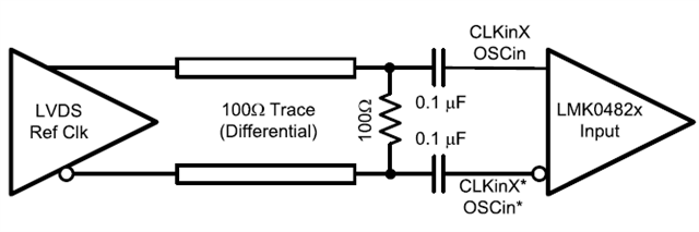
I have a question about the recommended AC-coupled LVDS input connection for LMK04828.

In the datasheet, the 100 Ω differential resistor is placed before the AC coupling capacitors. But in many other LVDS application notes and reference designs, the 100 Ω termination is usually placed after the capacitors, near the receiver.

Could you please help explain why LMK04828 uses this different connection method?

Is it because the LMK04828 input has internal biasing, so the resistor is mainly used to provide the proper load for the LVDS driver rather than acting as a conventional receiver-side termination?

Also, what would happen if the 100 Ω resistor were placed after the AC coupling capacitors near the LMK04828 input instead?

Thank you.

  • Hello, we have received your case and the investigation will take some time. Thank you for your patience.

  • Hello,

    I would like to kindly follow up on this case.
    Please let me know if there is any update, or if you need any additional information from my side.

    Best regards

  • The 100ohms resistor is the load to the driver. 

    LVDS is a current source driver, so the 100ohms resistor should be DC-couple to the driver.

    CLKin pins of LMK04828 have internal bias, so they should be DC-isolated from the driver. As a result, the correct configuration is as follows:

    If CLKin is configured as Bipolar input, it is still ok to have the resistor on the right hand side of the capacitor. But this is not an idea configuration to the LVDS driver.

  • Thank you for the clarification.

    I understand your point that the 100 ohm resistor is the load for the LVDS driver, and that the CLKin pins of LMK04828 have internal bias and therefore should be DC-isolated from the driver.

    However, I am still having difficulty understanding the physical reason in more detail. Could you please help explain this more deeply?

    My confusion is the following:

    1. Many other LVDS AC-coupled designs place the 100 ohm resistor on the receiver side, after the AC coupling capacitors, and the LVDS driver still works normally. Why is that still acceptable in many cases?

    2. For LMK04828, when the 100 ohm resistor is placed before the AC coupling capacitors, what exactly does the LVDS driver “see” differently compared with the case where the resistor is placed after the capacitors?

    3. From the driver point of view, is the key issue related to:

      DC bias condition,

      output stage compliance,

      startup / low-frequency behavior,

      common-mode operating point,

      or something else?

    4. If the resistor is placed after the capacitors, what is the actual drawback?

      Is it only “not ideal but usually still works”?

      Or can it affect amplitude accuracy, waveform quality, jitter, common-mode behavior, or robustness margin?

    5. Could you please explain this using the equivalent circuit or current path point of view?
      I think that would help me understand why the recommended placement for LMK04828 is different from many common LVDS examples.

    If possible, a comparison between:

    • resistor before capacitor

    • resistor after capacitor

    would be very helpful.

    Best regards,
    jr

  • I would like to add one important detail about my application.

    In my design, the signal driving the LMK04828 CLKin pins is not directly from a standard LVDS driver output. The signal path goes through two baluns:

    • first, differential to single-ended

    • then single-ended back to differential

    So the final signal applied to the LMK04828 input is a differential signal reconstructed through two baluns.

    Because of this, I would like to confirm whether the previous explanation
    “LVDS is a current source driver, so the 100 ohms resistor should be DC-coupled to the driver”
    still fully applies to my case.

    My concern is that after passing through the two baluns, the source seen by LMK04828 may no longer behave exactly like a standard LVDS current-source driver.

    Could you please clarify whether, in this balun-based application, the recommendation of placing the 100 ohm resistor before the AC coupling capacitors is still for the same reason, or whether the rationale changes in this case?