ADS122S14: ADS122S14:ADS122S14 No SPI Response After Enabling IDAC 200μA Output

Part Number: ADS122S14
Other Parts Discussed in Thread: MSPM0G3507,

Hardware setup:

MCU: MSPM0G3507

ADC: ADS122S14

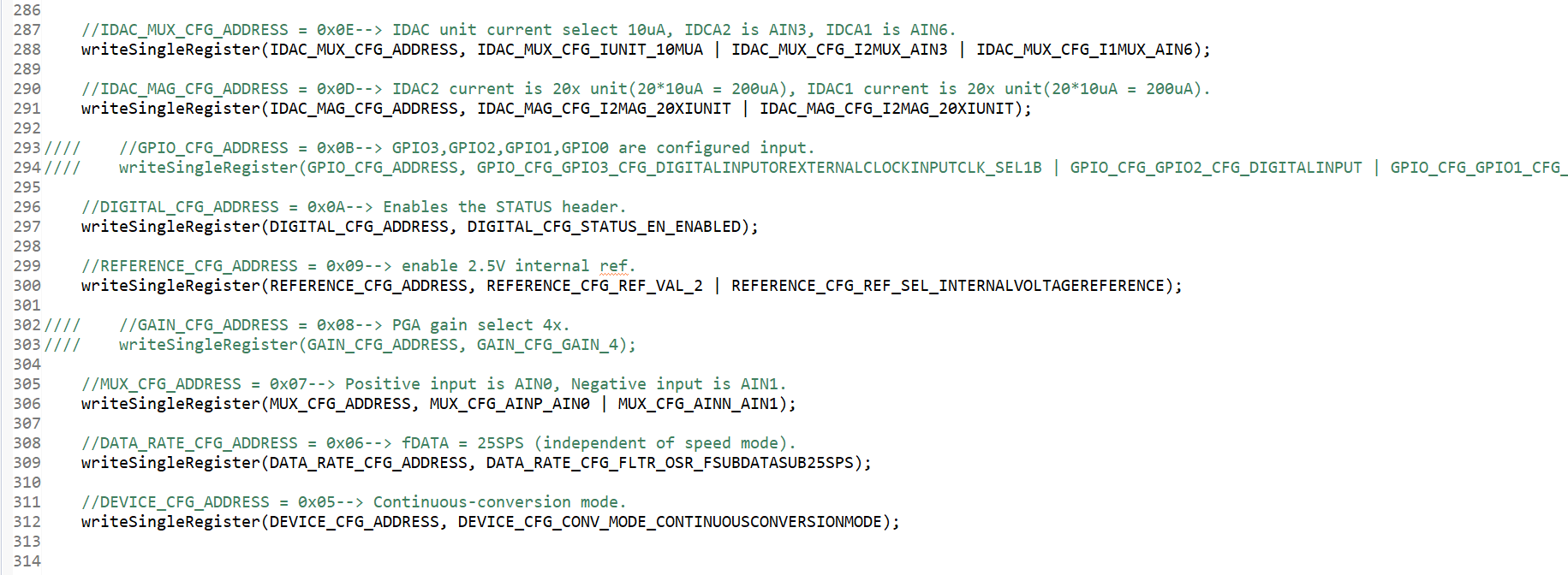
problem:The initialization using the DEMO program can communicate with the ADC. However, after modifying the initialization, I was unable to communicate with the ADC, and even when I used the DEMO program for initialization again, I still couldn't communicate with the ADC. Has the ADC failed?I need design a three-wire PT100 RTD measurement and two IDAC current source.Could you please help me analyze what caused this? 

demo progrom:

demo.png

my progrom:

myself.png

  • Hi,

    Thank you for contacting TI China E2E forum and choosing our products as part of your solution.

    Regarding your query, please give us some time to confirm this issue.

  • I found that by enabling only IDAC1, the communication seems to be working properly.

  • 	//IDAC_MUX_CFG_ADDRESS = 0x0E--> IDAC unit current select 10uA, IDCA1 is AIN6.
    	writeSingleRegister(IDAC_MUX_CFG_ADDRESS, IDAC_MUX_CFG_IUNIT_10MUA | IDAC_MUX_CFG_I1MUX_AIN6);
    
    	//IDAC_MAG_CFG_ADDRESS = 0x0D--> IDAC1 current is 90x unit(90*10uA = 900uA).
    	writeSingleRegister(IDAC_MAG_CFG_ADDRESS, IDAC_MAG_CFG_I1MAG_90XIUNIT);
    
    	//DIGITAL_CFG_ADDRESS = 0x0A--> Enables the STATUS header.
    	writeSingleRegister(DIGITAL_CFG_ADDRESS, DIGITAL_CFG_STATUS_EN_ENABLED);
    
    	//REFERENCE_CFG_ADDRESS = 0x09--> enable REF buffer.
    	writeSingleRegister(REFERENCE_CFG_ADDRESS, /*REFERENCE_CFG_REFP_BUF_EN_ENABLED |*/ REFERENCE_CFG_REF_VAL_2);
    
    	//MUX_CFG_ADDRESS = 0x07--> Positive input is AIN0, Negative input is AIN1.
    	writeSingleRegister(MUX_CFG_ADDRESS, MUX_CFG_AINP_AIN0 | MUX_CFG_AINN_AIN1);
    
    	//DATA_RATE_CFG_ADDRESS = 0x06--> fDATA = 25SPS (independent of speed mode).
    	writeSingleRegister(DATA_RATE_CFG_ADDRESS, DATA_RATE_CFG_FLTR_OSR_FSUBDATASUB25SPS);
    
    	//DEVICE_CFG_ADDRESS = 0x05--> Continuous-conversion mode.
    	writeSingleRegister(DEVICE_CFG_ADDRESS, DEVICE_CFG_CONV_MODE_CONTINUOUSCONVERSIONMODE);
    this is my progrom. 

  • Thank you for your question regarding the ADS122S14 SPI communication.

    When enabling the 200µA IDAC output, please verify the following operating conditions:

    1. IDAC Compliance Voltage: The voltage at the IDAC pin must remain below (AVDD - 0.3V). If your load resistance is too high, the IDAC cannot maintain the programmed current, which may cause the device to become unresponsive.

    2. Load Resistance Calculation: For 200µA IDAC with typical AVDD = 3.3V, maximum load resistance ≈ (3.0V / 200µA) = 15kΩ. Please check if your load exceeds this limit.

    3. Operating Mode: Verify the device is in normal operating mode, not standby or power-down, as SPI communication requires active operation.

    Troubleshooting steps:

    • Measure the voltage at your IDAC pin during operation
    • Reduce load resistance if voltage approaches AVDD
    • Verify SPI communication works with IDAC disabled to isolate the issue

    Please refer to the ADS122S14 datasheet Section 7.3.8 (IDAC) for detailed specifications and operating conditions.