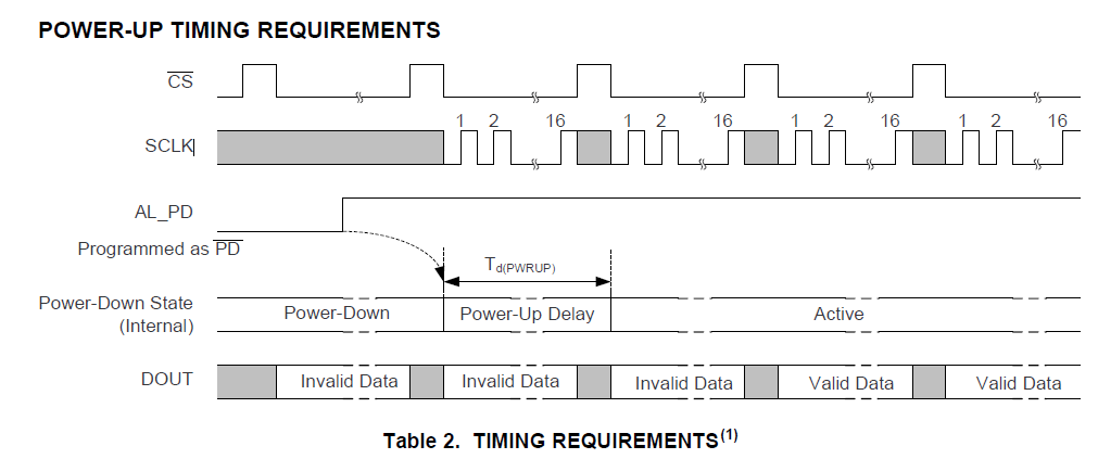
ADS8638根据手册上看写寄存器的时候,DOUT应该是0x0000的,但是为什么我写寄存器的时候,同时有数据输出?

以下是我的代码
#include "DSP2833x_Device.h"     // DSP2833x Headerfile Include File
#include "DSP2833x_Examples.h"   // DSP2833x Examples Include File
#include "SciSetup.h"

#define	  LedReg	(*((volatile  Uint16 *)0x41FF))
Uint16    *ExRamStart = (Uint16 *)0x100000;

void senddata(Uint16 a, int num);

#define ALPD GpioDataRegs.GPADAT.bit.GPIO26

// Prototype statements for functions found within this file.
// interrupt void ISRTimer2(void);
void delay_loop(void);
void spi_xmit(Uint16 a);
void spi_fifo_init(void);
void spi_init(void);
void error(void);
unsigned int Spi_TxReady(void);
unsigned int Spi_RxReady(void);

void main(void)
{
   Uint16 sdata;  // send data
   Uint16 rdata;  // received data

// Step 1. Initialize System Control:
// PLL, WatchDog, enable Peripheral Clocks
// This example function is found in the DSP2833x_SysCtrl.c file.
   InitSysCtrl();

// Step 2. Initalize GPIO:
// This example function is found in the DSP2833x_Gpio.c file and
// illustrates how to set the GPIO to it's default state.
// InitGpio();  // Skipped for this example
// Setup only the GP I/O only for SPI-A functionality
// This function is found in DSP2833x_Spi.c

   InitXintf16Gpio();	//zq

   InitSpiaGpio();

   EALLOW;
      GpioCtrlRegs.GPAMUX2.bit.GPIO26 = 0;
      GpioCtrlRegs.GPAPUD.bit.GPIO26=0;
      GpioCtrlRegs.GPADIR.bit.GPIO26 = 1;
      EDIS;

// Step 3. Clear all interrupts and initialize PIE vector table:
// Disable CPU interrupts
   DINT;

// Initialize PIE control registers to their default state.
// The default state is all PIE interrupts disabled and flags
// are cleared.
// This function is found in the DSP2833x_PieCtrl.c file.
   InitPieCtrl();

// Disable CPU interrupts and clear all CPU interrupt flags:
   IER = 0x0000;
   IFR = 0x0000;

// Initialize the PIE vector table with pointers to the shell Interrupt
// Service Routines (ISR).
// This will populate the entire table, even if the interrupt
// is not used in this example.  This is useful for debug purposes.
// The shell ISR routines are found in DSP2833x_DefaultIsr.c.
// This function is found in DSP2833x_PieVect.c.
   InitPieVectTable();

// Step 4. Initialize all the Device Peripherals:
// This function is found in DSP2833x_InitPeripherals.c
// InitPeripherals(); // Not required for this example
   spi_fifo_init();	  // Initialize the Spi FIFO
   spi_init();		  // init SPI


// Step 5. User specific code:
// Interrupts are not used in this example.
	LedReg = 0xFF;


		ALPD=1;		  //PowerUP
//	 	spi_xmit(0x080E);//PowerDown
//		spi_xmit(0x0800);//PowerUp

     for(;;)
      {
        // Transmit data
    	 spi_xmit(0x0201);//自动采集

      }

}


// Step 7. Insert all local Interrupt Service Routines (ISRs) and functions here:

void delay_loop()
{
    long      i;
    for (i = 0; i < 1000000; i++) {}
}


void spi_init()
{
	SpiaRegs.***.all =0x000F;	             // Reset on, falling edge, 16-bit char bits
	SpiaRegs.***.all =0x0006;    		     // Enable master mode, normal phase,
                                                 // enable talk, and SPI int disabled.
	SpiaRegs.SPIBRR =0x00FF;
	SpiaRegs.***.all =0x008F; 		// relinquish SPI from reset

    SpiaRegs.SPIPRI.bit.FREE = 1;                // Set so breakpoints don't disturb xmission
}

void spi_xmit(Uint16 a)
{

	Uint16 rdata1;  // received data
	if(Spi_TxReady() == 1)
	{
		SpiaRegs.SPITXBUF=a;
	}
	while(Spi_TxReady() != 1)
	{

	}

	if(Spi_RxReady() == 1)
	{
	   rdata1 = SpiaRegs.SPIRXBUF;
	 }

	delay_loop();
}

void spi_fifo_init()
{
// Initialize SPI FIFO registers
    SpiaRegs.SPIFFTX.all=0xA040;
    SpiaRegs.SPIFFRX.all=0x204f;
    SpiaRegs.SPIFFCT.all=0x0;
}

unsigned int Spi_TxReady(void)	//发送就绪
{

	unsigned int i = 0;
	if(SpiaRegs.SPISTS.bit.BUFFULL_FLAG == 1)
{
	i = 0;
}
else
{
	i = 1;
}
	return (i);
}

unsigned int Spi_RxReady(void)	//接收就绪
{

	unsigned int i = 0;
	if(SpiaRegs.SPISTS.bit.INT_FLAG == 1)
{
	i = 0;
}
else
{
	i = 1;
}
	return (i);
}


//===========================================================================
// No more.
//===========================================================================