If you have a related question, please click the "Ask a related question" button in the top right corner. The newly created question will be automatically linked to this question.
The lead-off detection principle is described in the Datasheet 9.3.2.4.3 Lead-Off Detection section.
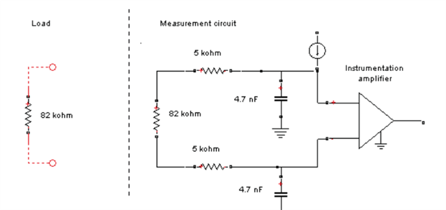
The basic principle is to inject an excitation current and measure the voltage to determine if the electrode is off. As shown in the lead-off detection functional block diagram in Figure 35, this circuit provides two different methods of determining the state of the patient electrode. The methods differ in the frequency content of the excitation signal. Lead-off can be selectively done on a per channel basis using the LOFF_SENSP and LOFF_SENSN registers.
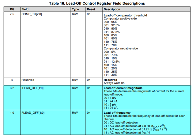
There are two types of excitation signals, DC signal excitation and AC signal excitation, corresponding to DC Lead-Off detection and AC Lead-Off detection, respectively. In DC lead-off method, the lead-off excitation is with a dc signal. In AC lead-off method, an in-band ac signal is used for excitation. It can be configured via the Lead-Off Control Register (0x04h LOFF register).
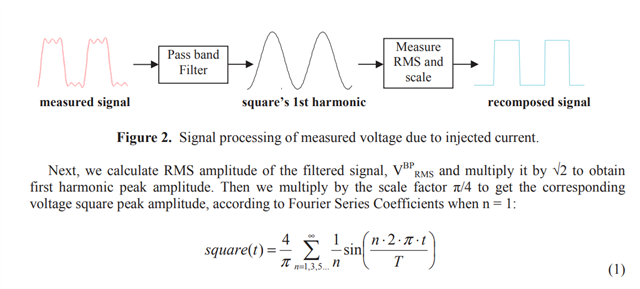
See application note below for more lead-off detection theory:
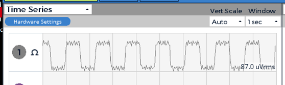
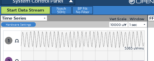
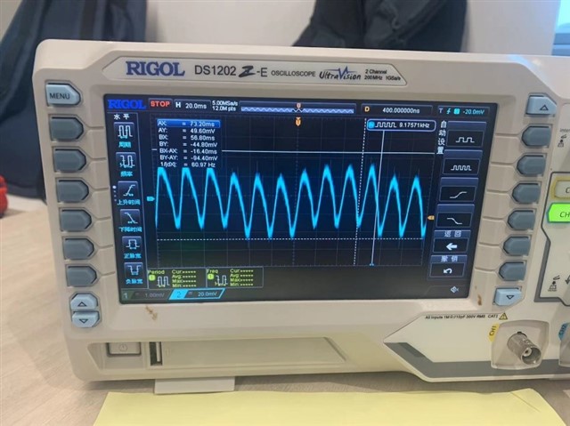
Hi, Amy Thank you for your prompt response. I am confused at the AC signal. I use lead-off detection and reading signals simultaneously ,when i have same setting but different connecting(resistance or oscilloscope),the signals was different ,so i want to know which waveform is right? so i can use it to calculate the resistance.