This thread has been locked.

If you have a related question, please click the "Ask a related question" button in the top right corner. The newly created question will be automatically linked to this question.

ADS8699: ADS8699

Part Number: ADS8699

void ADS8699_Init(void) {

// 设置复位和电源控制寄存器(正常模式)

//ADS8699_WriteRegister(0x05, 0x0069); // 写入保护键
ADS8699_WriteRegister(RST_PWRCTL_REG, 0x6900);

// 设置输入范围为±5.12V
ADS8699_WriteRegister(RANGE_SEL_REG, 0x0003);

// 设置SDI控制寄存器(SPI模式0)
ADS8699_WriteRegister(SDI_CTL_REG, 0x0000);

// 设置SDO控制寄存器(自动模式、外部时钟控制)
ADS8699_WriteRegister(SDO_CTL_REG, 0x0000);

// 设置数据输出控制寄存器(输出原始转换结果)
ADS8699_WriteRegister(DATAOUT_CTL_REG, 0x1000);
void ADS8699_WriteRegister(uint16_t address, uint16_t data) {
uint32_t reg_value = (0xD0000000 | (address << 16) | data); // 构造32位寄存器值
uint16_t buf[2];

buf[0] = (reg_value >> 16) & 0xFFFF; // 高16位
buf[1] = reg_value & 0xFFFF; // 低16位

HAL_GPIO_WritePin(SPI_CS_GPIO_Port, SPI_CS_Pin, GPIO_PIN_RESET); // CS低电平
if (HAL_SPI_Transmit(&hspi1, (uint8_t*)buf, 4, 50000) != HAL_OK) {
Error_Handler();
}
HAL_GPIO_WritePin(SPI_CS_GPIO_Port, SPI_CS_Pin, GPIO_PIN_SET); // CS高电平
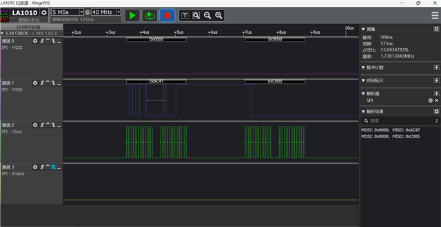
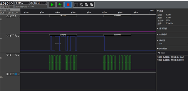
}I am communicating with the ADS8699 via STM32L431. After sending a configuration command, for example, the 32-bit data for the configuration register such as 0XD004 and 0x6900, the register returns the command I configured to me. How can I determine whether the configuration is successful?

  • 您好,
    已经收到了您的案例,调查需要些时间,感谢您的耐心等待。

  • Thank you for your reply. I'm currently unsure how to parse the response data when sending configuration commands. However, I can see that the register status is already configured in the second frame when I use the READ-HWORD command. I'd like to confirm that, when reading data periodically in automatic mode, the host can obtain data by sending 0x00. Here is the function, and I appreciate your help:
    c复制
    uint32_t Read_ADS8699(void) {
        uint32_t command = 0xC8000000;  // Command to read the data register (address 0x00)
        uint16_t tx_buffer[2] = {0x0000};  // Transmission buffer initialized with 0x0000
        uint16_t rx_buffer[2];  // Reception buffer
    
        // Pull CS pin low to start communication
        HAL_GPIO_WritePin(SPI_CS_GPIO_Port, SPI_CS_Pin, GPIO_PIN_RESET);
        HAL_SPI_TransmitReceive(&hspi1, (uint8_t*)tx_buffer, (uint8_t*)rx_buffer, 2, HAL_MAX_DELAY);  // Transmit the read command and receive the first 16-bit data
    
        // Combine the 18-bit data
        uint32_t data = ((uint32_t)(rx_buffer[0] & 0x00FF) << 16) | rx_buffer[1];  // Shift the upper 8 bits left by 16 positions and combine with the lower 16 bits
        //data = data >> 6;  // Uncomment this line if you need to right-shift the data by 6 bits (not necessary in this case)
    
        // Pull CS pin high to end communication
        HAL_GPIO_WritePin(SPI_CS_GPIO_Port, SPI_CS_Pin, GPIO_PIN_SET);
    
        return data;
    }
  • I have configured the ADS8699 to set the voltage range to ±5.12V through the following register settings:
    c复制
    void SDI_REG_WRITE(void) // Set range
    {
        uint8_t command = 0xD0;
        uint8_t addr = 0x08;
        uint8_t H = 0x00;
        uint8_t L = 0x00;
        HAL_GPIO_WritePin(SPI_CS_GPIO_Port, SPI_CS_Pin, GPIO_PIN_RESET);
        HAL_SPI_Transmit(&hspi1, &command, 1, HAL_MAX_DELAY);  // Send write command
        HAL_SPI_Transmit(&hspi1, &addr, 1, HAL_MAX_DELAY);  // Send register address
        HAL_SPI_Transmit(&hspi1, &H, 1, HAL_MAX_DELAY);  // Send high byte
        HAL_SPI_Transmit(&hspi1, &L, 1, HAL_MAX_DELAY);  // Send low byte
        HAL_GPIO_WritePin(SPI_CS_GPIO_Port, SPI_CS_Pin, GPIO_PIN_SET);  
    }
    
    void RANG_REG_WRITE(void) // Set range
    {
        uint8_t command = 0xD0;
        uint8_t addr = 0x14;
        uint8_t H = 0x00;
        uint8_t L = 0x03;
        HAL_GPIO_WritePin(SPI_CS_GPIO_Port, SPI_CS_Pin, GPIO_PIN_RESET);
        HAL_SPI_Transmit(&hspi1, &command, 1,_MAX HAL_DELAY);  // Send write command
        HAL_SPI_Transmit(&hspi1, &addr, 1, HAL_MAX_DELAY);  // Send register address
        HAL_SPI_Transmit(&hspi1, &H, 1, HAL_MAX_DELAY);  // Send high byte
        HAL_SPI_Transmit(&hspi1, &L, 1, HAL_MAX_DELAY);  // Send low byte
        HAL_GPIO_WritePin(SPI_CS_GPIO_Port, SPI_CS_Pin, GPIO_PIN_SET);  
    }
    
    void RST_REG_WRITE(void) // Reset register
    {
        uint8_t command = 0xD0;
        uint8_t addr = 0x04;
        uint8_t H = 0x69;
        uint8_t L = 0x00;
        HAL_GPIO_WritePin(SPI_CS_GPIO_Port, SPI_CS_Pin, GPIO_PIN_RESET);
        HAL_SPI_Transmit(&hspi1, &command, 1, HAL_MAX_DELAY);  // Send write command
        HAL_SPI_Transmit(&hspi1, &addr, 1, HAL_MAX_DELAY);  // Send register address
        HAL_SPI_Transmit(&hspi1, &H, 1, HAL_MAX_DELAY);  // Send high byte
        HAL_SPI_Transmit(&hspi1, &L, 1, HAL_MAX_DELAY);  // Send low byte
        HAL_GPIO_WritePin(SPI_CS_GPIO_Port, SPI_CS_Pin, GPIO_PIN_SET);  
    }
    
    void RST1_REG_WRITE(void) // Reset register
    {
        uint8_t command = 0xD0;
        uint8_t addr = 0x04;
        uint8_t H = 0x00;
        uint8_t L = 0x00;
        HAL_GPIO_WritePin(SPI_CS_GPIO_Port, SPI_CS_Pin, GPIO_PIN_RESET);
        HAL_SPI_Transmit(&hspi1, &command, 1, HAL_MAX_DELAY);  // Send write command
        HAL_SPI_Transmit(&hspi1, &addr, 1, HAL_MAX_DELAY);  // Send register address
        HAL_SPI_Transmit(&hspi1, &H, 1, HAL_MAX_DELAY);  // Send high byte
        HAL_SPI_Transmit(&hspi1, &L, 1, HAL_MAX_DELAY);  // Send low byte
        HAL_GPIO_WritePin(SPI_CS_GPIO_Port, SPI_CS_Pin, GPIO_PIN_SET);  
    }
    
    void DATA_REG_WRITE(void) // Data output format register
    {
        uint8_t command = 0xD0;
        uint8_t addr = 0x10;
        uint8_t H = 0x00;
        uint8_t L = 0x00;
        HAL_GPIO_WritePin(SPI_CS_GPIO_Port, SPI_CS_Pin, GPIO_PIN_RESET);
        HAL_SPI_Transmit(&hspi1, &command, 1, HAL_MAX_DELAY);  // Send write command
        HAL_SPI_Transmit(&hspi1, &addr, 1, HAL_MAX_DELAY);  // Send register address
        HAL_SPI_Transmit(&hspi1, &H, 1, HAL_MAX_DELAY);  // Send high byte
        HAL_SPI_Transmit(&hspi1, &L, 1, HAL_MAX_DELAY);  // Send low byte
        HAL_GPIO_WritePin(SPI_CS_GPIO_Port, SPI_CS_Pin, GPIO_PIN_SET);  
    }
    However, when I read the converted value from the ADS8699 using the following function, the result is always around 6.2V, while the actual input voltage is -4.8V:
    c复制
    uint32_t Read_ADS8699(void) {
        uint32_t command = 0xC8000000;  // Command to read data register (address 0x00)
        uint8_t tx_buffer[4];
        uint8_t rx_buffer[4];
    
        tx_buffer[0] = 0x00;
        tx_buffer[1] = 0x00;
        tx_buffer[2] = 0x00;
        tx_buffer[3] = 0x00;
    
        // CS low, start communication
        HAL_GPIO_WritePin(SPI_CS_GPIO_Port, SPI_CS_Pin, GPIO_PIN_RESET);
        HAL_SPI_TransmitReceive(&hspi1, (uint8_t*)tx_buffer, (uint8_t*)rx_buffer, 4, HAL_MAX_DELAY);  // Transmit and receive data
        uint32_t data = rx_buffer[0] << 24;
        data |= rx_buffer[1] << 16;
        data |= rx_buffer[2] << 8;
        data |= rx_buffer[3];
        data = (data & 0xfffc0000) >> 14;  // Extract the 18-bit data
    
        // CS high, end communication
        HAL_GPIO_WritePin(SPI_CS_GPIO_Port, SPI_CS_Pin, GPIO_PIN_SET);
    
        return data;
    }
    I'm not sure why the reading is incorrect. Can you help me identify the issue?
  • Who is the customer and what is the application/end equipment?  Can you please provide screen shots fro an o'scop or logic analyzer?

  • Using the STM32L431 chip, the ADS8699 is configured with a voltage range of ±5.12V. The following two screenshots from the logic analyzer show +5V and -5V inputs, respectively. However, the converted results seem to be incorrect.

  • Can you please supply the o'scope or logic analyzer plot that was asked for?