DP83TD510E: BACK TO BACK

Part Number: DP83TD510E

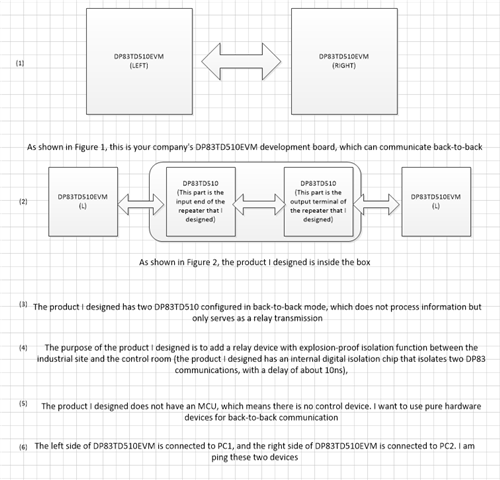
Hello, I would like to inquire about a question regarding DP83TD510E. I am currently designing a repeater that does not require an MCU and uses pure hardware. I aim to achieve back-to-back connection. The conceptual diagram is as follows: Ethernet → DP83TD510EVM → DP83TD510E → DP83TD510E → DP83TD510EVM → Ethernet
The product I designed is placed in the middle of DP83TD510EVM, serving as an isolation repeater. Current tests have revealed that there is a waveform in the circuit, but PING is unsuccessful. I hope you can help me with this issue. I have attached the schematic diagram, could you please take a look and let me know if there are any issues with the design. Thank you.PHD-APL-DEMO.pdf

  • 您好,收到了您的案例,调查需要些时间,感您的耐心等待。

  • 您好,

    请允许我们的团队在下周审阅原理图。 我将回复此主题。 感谢您的耐心。

  • Hi , 

    I wanted some additional information about your setup.

    What exactly is the purpose of this "isolation repeater" placed between the 2 PHYs? The recommendation for back-to-back operation, as listed in the datasheet, simply has the MII lines directly connected to each other, ensuring a impedance of 50 Ohms on each line. I am worried that this component may be changing the parameters of the MII interface, such as affecting the slew rate, total impedance, etc which may be the reason for communication failure. 

    Do you have 4 total 510 devices in this setup? Are you trying to ping the ethernet device that is connected after the last 510?

    Can you check the register 0x0010 for the link status in all these 510 devices? I want to make sure that there is an active link.

    Another thing we could try would be to use a MII Loopback on the last 510 device to ensure that the data is going through all the different 510s correctly. Like you mentioned, there are waveforms on the MDI lines according to your testing, but these could just be Auto-negotiation pulses, or idle symbols. Doing this loopback would give us more confidence that the datapath is stable. 

    Best,

    Lydia