

Part Number: DS90UB983-Q1
你好,我们使用UB983加串器搭配UB984解串器使用,现在使用983打pattern验证通路是否有问题,但打pattern后未出图,请问984也要对应的设置pattern吗,并且984有相关的寄存器能看Video Lock吗,就是看解串器是否接收到数据
This thread has been locked.
If you have a related question, please click the "Ask a related question" button in the top right corner. The newly created question will be automatically linked to this question.
Original question:

Part Number: DS90UB983-Q1
你好,我们使用UB983加串器搭配UB984解串器使用,现在使用983打pattern验证通路是否有问题,但打pattern后未出图,请问984也要对应的设置pattern吗,并且984有相关的寄存器能看Video Lock吗,就是看解串器是否接收到数据
很乐意就此提供支持。请问一级供应商和原始设备制造商分别是哪家?
现在使用983打pattern验证通路是否有问题
在测试序列化器上的PATGEN之前,您是否已在反序列化器上成功启动PATGEN?此操作无需连接序列化器,可验证反序列化器与显示器之间的信号路径是否有效。
请问984也要对应的设置pattern吗
在串行器上运行PATGEN时,反串行器上的PATGEN无需启用,但反串行器仍需按常规端到端应用程序的方式进行配置。能否请您提供客户的初始化脚本?同时希望查看串行器和反串行器两端的MODE_SEL跳线设置,以确认其软件配置与硬件配置相匹配。
并且984有相关的寄存器能看Video Lock吗,就是看解串器是否接收到数据
没有视频锁存寄存器,但FPD-Link IV解串器确实包含一个DTG模块,其内部寄存器可测量输入时序。更多详情请参阅UB984数据手册第6.3.3节。
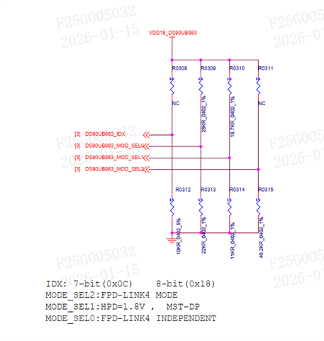
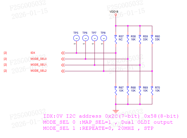 您好,感谢您的回复。图一是983的MODE_SEL跳线设置,图二是984的MODE_SEL跳线设置。后面我们对984的电阻进行了更改,R58换成82K,R68换成42K,R59换成27K,R69换成100K。
下面是我们的初始化脚本,我们不确定的几点是,虽然MODE_DEL0设置成FPD4 Independent,但我们实际只接了一个屏,一个984解串器,所以配置时能否当成Single Link配置,以及关闭Daisy-chain。至于一级供应商和原始设备制造商,由于是公司采购的,我暂时还不清楚。
"""
Copyright (C) 2021 Texas Instruments Incorporated - http://www.ti.com/
ALL RIGHTS RESERVED
"""
"""
Global Setups - Do Not Change
"""
FPD4 = [0,0]
FPD4Rate = [0,0]
FPD3Stream = [0,0]
THW = [0,0,0,0]
TVW = [0,0,0,0]
AHW = [0,0,0,0]
AVW = [0,0,0,0]
HBP = [0,0,0,0]
VBP = [0,0,0,0]
HSW = [0,0,0,0]
VSW = [0,0,0,0]
HFP = [0,0,0,0]
VFP = [0,0,0,0]
HSP = [0,0,0,0]
VSP = [0,0,0,0]
PCLK = [0,0,0,0]
Bits_per_pixel = [0,0,0,0]
PATGEN = [0,0,0,0]
CropEnable = [0,0,0,0]
FilterEnable = [0,0,0,0]
CropXStart = [0,0,0,0]
CropXStop = [0,0,0,0]
CropYStart = [0,0,0,0]
CropYStop = [0,0,0,0]
FilterEnable = [0,0,0,0]
FilterA = [0,0,0,0]
FilterN = [0,0,0,0]
DSI_PORT0 = 0
DSI_PORT1 = 0
MAPSEL = [0,0]
OLDIBpp = [0,0]
HDCP_FPD3 = [0,0]
Des0_DaisyVPs = [0,0,0,0]
FPD4RateDaisy0 = [0,0,0]
FPD4RateDaisy1 = [0,0,0]
FPD4Daisy0 = [1,1]
DP0_ON = [0,0,0,0]
DP1_ON = [0,0,0,0]
DP_Output_0_Source = [0,0,0,0]
DP_Output_1_Source = [0,0,0,0]
Des_Device = [0,0,0,0]
DP_Rate = [0,0,0,0]
DP_Lane_Num = [0,0,0,0]
RGBMode = [0,0,0,0]
OLDIEnabled = [0,0,0,0]
MAPSEL0 = [0,0,0,0]
MAPSEL1 = [0,0,0,0]
RGBBpp = [0,0,0,0]
OLDIBpp0 = [0,0,0,0]
OLDIBpp1 = [0,0,0,0]
OLDI_RGB_Port0_Source = [0,0,0,0]
OLDI_Port1_Source = [0,0,0,0]
DaisyConf = [0,0,0,0]
FPD4LinkEN0 = [0,0,0,0]
FPD4LinkEN1 = [0,0,0,0]
DES_Display_SSCG = [0,0,0,0]
DES_Display_SSCG_FDEV = [0,0,0,0]
DES_Display_SSCG_FMOD = [0,0,0,0]
serFPDSSCG = [0,0]
serFPDSSCG_fdev = [0,0]
serFPDSSCG_fmod = [0,0]
eFuseOV = 0
FPD3DaisyVP_P0 = [0,0,0]
FPD3DaisyVP_P1 = [0,0,0]
DES_BC_SSCG = [0,0,0,0]
DES_BC_SSCG_FDEV = [0,0,0,0]
DES_BC_SSCG_FMOD = [0,0,0,0]
DP_Stream_BPP = [0,0]
MST_Source = [0,0,0,0]
DES_FC_SSCG = [0,0,0]
DES_FC_SSCG_FDEV = [0,0,0]
DES_FC_SSCG_FMOD = [0,0,0]
disable_FIFO_errata = 0
Override_Color = 0
"""
General Configurations - Set by the user
"""
# Serializer Address
# Ignore if using DES only configurations
SER_Address = 0x18
# First deserializer Address Port 0
# For dual FPD-Link configurations use this address for the first deserializer. P1 addresses are ignored
# For single port 0 or independent FPD configurations this is the address of the first DES attached to port 0
DES0_Address = 0x58
DES0_Alias = 0x58
# First deserializer Address Port 1
# Only used for single port 1 or independent FPD link configurations
P1DES0_Address = 0x58
P1DES0_Alias = 0x5c
# Deserializer Daisy Chain Addresses
DES1_Address = 0x58
DES1_Alias = 0x5e
DES2_Address = 0x58
DES2_Alias = 0x60
DES3_Address = 0x58
DES3_Alias = 0x62
# Serializer Device
# For FPD IV serializer, options are 983 or 981, HH983_ES1.0, HH983_CS1.0
# For FPD III serializer, options are 925, 926, 921, 929, 949, 941AS, 947
Device = "983"
# DES eFuse Override Enable
# Enabling eFuse override will generate a script to
# manually override the eFuse settings for the DES
# to the final production version when using either 984 or 988
eFuseOV = 0
# If Des_Only = 1, 98x Serialzier configuration will be ignored but
# 94x/92x SER configuration will be included if Fes_FPD3_Only = 1
# Only applicable for configurations with 988/984 DES
# Use this setting when the SER is 94x or 92x FPD III or to generate a 98x to 98x script
# which only includes the DES side configurations
Des_Only = 0
# Select deserializer PatGen enable
# Only applicable for FPD IV DES configurations - ignore for FPD III DES configurations
# 0 = disable
# 1 = enable
DES_Patgen_on = 0
# Ignored for FPD IV configurations
# Set to 1 when using FPD IV serializer to FPD IV deserializer in FPD III link mode
# Set to 0 when using FPD III serializer to FPD IV deserializer
FPD4DES_FPD3MODE = 0
# Set the deserializer FPD port configuration
# Ignored if serializer is 98x
# Options:
# FPD3 Dual = 5
# FPD3 Single Port 0 = 6
DES_FPDIII_Conf = 5
# Set the serializer FPD port configuration
# Options:
# FPD4 Dual = 1
# FPD4 Single Port 0 = 2
# FPD4 Single Port 1 = 3
# FPD4 Independent = 4
# FPD3 Dual = 5
# FPD3 Single Port 0 = 6
# FPD3 Single Port 1 = 7
# FPD3 Independent = 8
# FPD4 Port 0/FPD3 Port 1 = 9
# FPD3 Port 0/FPD4 Port 1 = 10
FPDConf = 2
# Configure Y split daisy chain topology
# In Y split daisy chain mode, the SER connects to two DES
# One or both of the connected DES connect to another downstream DES via daisy chain
# In Y split daisy chain mode deserializers are numbered as follows:
# SER Port 0 -> DES0 -> DES2
# SER Port 1 -> DES1 -> DES3
# Options:
# 0: Straight line daisy chain mode: SER -> DES -> DES -> DES -> DES
# 1: Y Split daisy chain mode
y_split_daisy = 0
# Enable HDCP1.4 per FPD Channel in FPD III mode (Only applicable for UH to UH connections)
# Only used for FPD III mode
# Options: 0 = No HDCP, 1 = HDCP Enabled
# HDCP[0] controls FPD port 0
# HDCP[1] controls FPD port 1
# Unused FPD ports are ignored and only the HDCP[0] setting is used for dual FPD modes
HDCP_FPD3[0] = 0
HDCP_FPD3[1] = 0
# Enter number of VPs used
# Options:
# 1 Display = 1 (VP0)
# 2 Displays = 2 (VP0/VP1)
# 3 Displays = 3(VP0/VP1/VP2)
# 4 Displays = 4 (VP0/VP1/VP2/VP3)
numVPs = 1
# Enter Video Processor 0 Properties
# THW = Horizontal Total Pixels = AHW + HBP + HFP + HSW
# TVW = Vertical Total Lines = AVW + VBP + VFP + VSW
# AHW = Hoizontal Active Pixels
# AVW = Vertical Active Lines
# HBP = Horizontal Back Porch Pixels
# VBP = Vertical Back Porch Pixels
# HSW = Horizontal Sync Width Pixels
# VSW = Vertical Sync Width Lines
# HSP = Horizontal Sync Polarity: 0 = Positive, 1 = Negative
# VSP = Vertical Sync Polarity: 0 = Positive, 1 = Negative
# PCLK = Pixel Clock Rate in MHz
# Bits_per_pixel = 18, 24, or 30 (30bpp only available for FPD IV)
# PATGEN = 1 - Generate PATGEN from the VP
# PATGEN = 0 - Configure the VP but don't enable PATGEN (use for end to end video)
# If Des is set to FPD3 mode only, VP0 timing is used to configure Des.
THW[0] = 2768
TVW[0] = 1652
AHW[0] = 2560
AVW[0] = 1600
HBP[0] = 60
VBP[0] = 18
HSW[0] = 60
VSW[0] = 2
HFP[0] = THW[0] - AHW[0] - HBP[0] - HSW[0]
VFP[0] = TVW[0] - AVW[0] - VBP[0] - VSW[0]
HSP[0] = 0
VSP[0] = 0
PCLK[0] = 274.3
Bits_per_pixel[0] = 24
PATGEN[0] = 0
# Crop and filter parameters (Optional - Ignored if CropEnable[x] is 0)
CropEnable[0] = 0
CropXStart[0] = 0
CropXStop[0] = 1399
CropYStart[0] = 0
CropYStop[0] = 1199
# Filter parameters (Optional - Ignored if FilterEnable[x] is 0)
FilterEnable[0] = 0
FilterA[0] = 1
FilterN[0] = 2
# Enter Video Processor 1 Properties (Optional)
THW[1] = 1650
TVW[1] = 750
AHW[1] = 1280
AVW[1] = 720
HBP[1] = 220
VBP[1] = 20
HSW[1] = 40
VSW[1] = 5
HFP[1] = THW[1] - AHW[1] - HBP[1] - HSW[1]
VFP[1] = TVW[1] - AVW[1] - VBP[1] - VSW[1]
HSP[1] = 0
VSP[1] = 0
PCLK[1] = 74.25
Bits_per_pixel[1] = 24
PATGEN[1] = 1
# Crop and filter parameters (Optional - Ignored if CropEnable[x] is 0)
CropEnable[1] = 0
CropXStart[1] = 1400
CropXStop[1] = 2799
CropYStart[1] = 0
CropYStop[1] = 1199
# Filter parameters (Optional - Ignored if FilterEnable[x] is 0)
FilterEnable[1] = 0
FilterA[1] = 1
FilterN[1] = 2
# Enter Video Processor 2 Properties (Optional)
THW[2] = 2020
TVW[2] = 590
AHW[2] = 1920
AVW[2] = 384
HBP[2] = 8
VBP[2] = 5
HSW[2] = 12
VSW[2] = 3
HFP[2] = THW[2] - AHW[2] - HBP[2] - HSW[2]
VFP[2] = TVW[2] - AVW[2] - VBP[2] - VSW[2]
HSP[2] = 0
VSP[2] = 0
PCLK[2] = 71.51
Bits_per_pixel[2] = 24
PATGEN[2] = 1
# Crop and filter parameters (Optional - Ignored if CropEnable[x] is 0)
CropEnable[2] = 1
CropXStart[2] = 2304
CropXStop[2] = 4223
CropYStart[2] = 0
CropYStop[2] = 383
# Filter parameters (Optional - Ignored if FilterEnable[x] is 0)
FilterEnable[2] = 0
FilterA[2] = 1
FilterN[2] = 2
# Enter Video Processor 3 Properties (Optional)
THW[3] = 2640
TVW[3] = 1500
AHW[3] = 2560
AVW[3] = 1440
HBP[3] = 40
VBP[3] = 40
HSW[3] = 32
VSW[3] = 10
HFP[3] = THW[3] - AHW[3] - HBP[3] - HSW[3]
VFP[3] = TVW[3] - AVW[3] - VBP[3] - VSW[3]
HSP[3] = 0
VSP[3] = 0
PCLK[3] = 100
Bits_per_pixel[3] = 24
PATGEN[3] = 0
# Crop and filter parameters (Optional - Ignored if CropEnable[x] is 0)
CropEnable[3] = 0
CropXStart[3] = 2560
CropXStop[3] = 3839
CropYStart[3] = 0
CropYStop[3] = 719
# Filter parameters (Optional - Ignored if FilterEnable[x] is 0)
FilterEnable[3] = 1
FilterA[3] = 1
FilterN[3] = 2
# Enter stream mapping for FPD3 Mode (ignored if using FPD4)
# Ignore map setting for unused port in single FPD3 mode
# If using dual mode, set FPD3Stream[0] and FPD3Stream[1] to the same VP
# Options: 0 = VP0, 1 = VP1, 2 = VP2, 3 = VP3: Maps the corresponding VP to the FPD3 port
FPD3Stream[0] = 0
FPD3Stream[1] = 0
# FPD4 Rate Selection (Gbps)
# Ignored if the port is set to FPD3 mode
# FPD4Rate[0] sets FPD TX Port 0
# FPD4Rate[1] sets FPD TX Port 1
# Options: 3.375, 6.75, 10.8, 13.5, 12.528
FPD4Rate[0] = 13.5
FPD4Rate[1] = 13.5
# FPD4 Port SSCG Configuration
# serFPDSSCG[0] controls FPD Port 0
# serFPDSSCG[1] controls FPD Port 1
# Options:
# 0 = Disabled
# 1 = Enable SSCG Center Spread
# 2 = Enable SSCG Down Spread
serFPDSSCG[0] = 0
serFPDSSCG[1] = 0
# Serializer SSCG FDEV %
# serFPDSSCG_fdev[0] controls FPD Port 0
# serFPDSSCG_fdev[1] controls FPD Port 1
# Ignored is serFPDSSCG = 0
# Sets the SSCG frequency deviation percentage for FPD4 port 0
# Options: 0-0.5 (%)
serFPDSSCG_fdev[0] = 0.5
serFPDSSCG_fdev[1] = 0.5
# Display SSCG FMOD kHz
# serFPDSSCG_fmod[0] controls FPD Port 0
# serFPDSSCG_fmod[1] controls FPD Port 1
# Ignored is DES_Display_SSCG = 0
# Set the SSCG modulation frequency for display interface SSCG
# Options: 30-33 (kHz)
serFPDSSCG_fmod[0] = 33
serFPDSSCG_fmod[1] = 33
# FPD4 Link Layer Selection for independent FPD IV Mode or mixed FPD III/IV modes
# Ignored for dual FPD IV or single FPD IV modes
# Select which VPs are forwarded to FPD Port 0 and Port 1 Link layers
# FPD4LinkEN0 controls SER FPD Port 0
# FPD4LinkEN1 controls SER FPD Port 1
# For example, to send VP 0 to port 0 and VP1 to port 1, use the following
# Note that in order to send any stream to both FPD ports, the FPD IV links rate must be the same
# FPD4LinkEN0 = [1,0,0,0]
# FPD4LinkEN1 = [0,1,0,0]
FPD4LinkEN0 = [1,0,0,0]
FPD4LinkEN1 = [0,1,0,0]
"""
983 Configs - Ignored if using 981
"""
# Disable DP FIFO Errata for debug
# Set to 1 in order to disable DP FIFO errata. The FIFO errata will restrict 983 operation to only the
# configured lane rate/lane count settings below. If the DP source lane count/rate are unknown or variable,
# disable the FIFO errata to test. TI recommends to apply the errata for optimal performance on production systems
disable_FIFO_errata = 1
# Set max DP lane count
# Options: 1, 2, 4
# Note - for UH983 or UB983, this setting must be set to the desired lane count for DP FIFO errata to execute sucessfully
DPlanes = 4
# Set max advertised DP lane rate in Gbps
# Options: 1.62, 2.7, 5.4, 8.1
# Note - for UH983 or UB983, this setting must be set to the desired link rate for DP FIFO errata to execute sucessfully
maxRate = 2.7
# Set MST or SST mode
# Options: 0 = SST mode, 1 = MST mode
# MST mode always uses VP0 for MST0 and VP1 for MST1
MST = 0
# Set which MST stream is mapped to each video processor
# Only used when MST = 1
# Options:
# 0: Video processor is mapped to MST0
# 1: Video processor is mapped to MST1
# Assignments: [VP0,VP1,VP2,VP3]
MST_Source = [0,1,0,0]
# Set DP receiver to expect SSC or no SSC from the DPTX
# This setting also configures the MAX_DOWNSPREAD capability bit in DPCD 0x00003[0]
# Options: 0 = No SSC, 1 = SSC
SSC = 0
#Set DP receiver to DP or eDP mode
# Options: 0 = DP Mode, 1 = eDP Mode
eDP = 0
# Set DP Stream BPP (Mandatory for HH983 ES1.0 and CS1.0, Optional for Ux983)
# Options: 30, 24, 18
# For SST, only stream 0 is used [stream0,0]
# For MST, format is [stream0,stream1]
# Example: Stream 0 is 24 bpp, Stream 1 is 30bpp
# Example Setting: [24,30]
DP_Stream_BPP = [24,24]
# Optional setting for Ux983 to override colorimetry for incoming streams
# When enabled, the SER will ignore colorimetry information from MSA
# and use the DP_Stream_BPP setting instead. This setting can improve error tolerance
# in high noise environments. CAUTION: The DP_Stream_BPP setting must match the colorimetry
# from the incoming video source, otherwise video distrotion or video wrap around will occur
Override_Color = 0
# EDID Options (SST only)
# Options:
# 0: EDID Support Disabled
# 1: EDID location = Internal SRAM using I2C1 bus
# 2: EDID location = Internal SRAM using I2C2 bus
# 3: EDID location = External EEPROM on HH983 I2C0 bus
# 4: EDID location = External EEPROM on HH983 I2C1 bus
# 5: EDID location = External EEPROM on HH983 I2C2 bus
# Note that the Internal SRAM EDID Example EDID included with the generated config for option 1
# does not change based on the VP settings. Custom EDIDs can be generated with external
# off the shelf free tools to replace the example EDID if needed
EDID = 0
# EDID 8-bit I2C Address (HH983 only)
EDID_ADDR = 0xA0
"""
981 Configs - Ignored if using 983
"""
#DSI ports active
# 0 = DSI 0 only
# 1 = DSI 1 only
# 2 = DSI 0 and DSI 1
DSI_PORTS_ACTIVE = 0
# Set max DSI lane count
# Options: 1, 2, 3, 4
Port0_DSI_Lanes = 4
Port1_DSI_Lanes = 4
# Set DSI in Continuous or Non-Continuous Clock
# 1 = Continuous ; 0 = Non-Continuous Clock
Port0_Contin = 1
Port1_Contin = 1
# Set the DSI rate
# example: 500 Mbps= 500, 1.2 Gbps = 1200Mbps
Port0_DSI_Rate = 891
Port1_DSI_Rate = 891
#DSI Source for Video Processors
#0 = DPHY 0 virtual Channel 0
#1 = DPHY 0 virtual Channel 1
#2 = DPHY 0 virtual Channel 2
#3 = DPHY 0 virtual Channel 3
#4 = DPHY 1 virtual Channel 0
#5 = DPHY 1 virtual Channel 1
#6 = DPHY 1 virtual Channel 2
#7 = DPHY 1 virtual Channel 3
VP_0_Source = 0
VP_1_Source = 0
VP_2_Source = 0
VP_3_Source = 0
"""
#####################################
DES0 (First Deserialzier) Configurations - Ignored for FPD III Modes
This section is referenced for FPD IV Dual mode or Single FPD IV Port 0 mode (NOT FPD IV Single Port 1 Mode)
#####################################
"""
# Des_Device
# Only used for FPD IV deserializer configurations - ignore if using FPD III deserializer
# Options 984, 988, HH984_CS1.0
Des_Device[0] = "984"
# Set the deserializer Daisy Chain TX FPD port configuration
# Options:
# Daisy Chaining Disabled = 0
# FPD4 Dual = 1
# FPD4 Single Port 0 = 2
# FPD4 Single Port 1 = 3 # Net yet functional
# FPD4 Independent = 4 # Net yet functional
# FPD3 Dual = 5
# FPD3 Single Port 0 = 6
# FPD3 Single Port 1 = 7
# FPD3 Independent = 8
# FPD4 Port 0/FPD3 Port 1 = 9 # Net yet functional
# FPD3 Port 0/FPD4 Port 1 = 10 # Net yet functional
DaisyConf[0] = 0
# Enable daisy chain TX forwarding for deserializer 0 (first DES in the chain)
# Set VPs 0-4 = 1 to enable forwarding of that VP to the next DES
# If all VP forwarding is set to 0, then daisy chaining is disabled
# Example: Forward only VP0 to the next DES: Des0_DaisyVPs = [1,0,0,0]
# Example Forward VP1 and VP2 to the next DES: Des0_DaisyVPs = [0,1,1,0]
Des0_DaisyVPs = [0,1,0,0]
# Set which VP is forwarded to chain chain output in FPD III mode
# FPD3DaisyVP_P0 controls daisy chain FPD port 0
# FPD3DaisyVP_P1 controls daisy chain FPD port 1
# FPD3DaisyVP_P0 and FPD3DaisyVP_P1 must be set to the same VP for dual FPD III mode
# Setting the daisy chain output to FPD III mode terminates the daisy chain at the connected deserializer
# This is ignored if the daisy chain is set up for FPD IV output mode
# Example: Forward VP1 to Daisy Chain Output in FPD III mode: FPD3DaisyVP[0] = 1
# Example: Forward VP3 to Daisy Chain Output in FPD III mode: FPD3DaisyVP[0] = 3
FPD3DaisyVP_P0[0] = 1
FPD3DaisyVP_P1[0] = 1
# FPD4 Rate Selection for DES0 Daisy Chain TX (Gbps)
# Ignored if the port is set to FPD3 mode
# FPD4RateDaisy0[0] sets DES0 Daisy Chain TX Port 0
# FPD4RateDaisy1[0] sets DES0 Daisy Chain TX Port 1
# Options: 3.375, 6.75, 10.8, 13.5, 12.528
FPD4RateDaisy0[0] = 6.75
FPD4RateDaisy1[0] = 6.75
# DES Daisy Chain FC SSCG Configuration
# SSCG options for the deserializer forward channel output
# Options:
# 0 = Disable SSCG on FPD forward channel daisy chain interface
# 1 = Enable SSCG with Center Spread
# 2 = Enable SSCg with Down Spread
DES_FC_SSCG[0] = 0
# FPD Daisy Chain FC SSCG FDEV %
# Ignored is DES_FC_SSCG = 0
# Sets the SSCG frequency deviation percentage for daisy chain forward channel interface SSCG
# Note: Combined FPD FC and BC FDEV should not exceed 0.5% for center spread or 0.25% for down spread
# Options: 0-0.5 (%) in Center Spread Mode
# Options: 0-0.25 (%) in Down Spread Mode
DES_FC_SSCG_FDEV[0] = 0.25
# DES Daisy Chain SSCG FMOD kHz
# Ignored is DES_FC_SSCG = 0
# Set the SSCG modulation frequency for daisy chain forward channel interface SSCG
# Options: 30-33 (kHz)
DES_FC_SSCG_FMOD[0] = 33
# FPD BC SSCG Configuration
# SSCG options for the deserializer back channel output
# Options:
# 0 = Disable SSCG on FPD back channel interface
# 1 = Enable SSCG with Center Spread
# 2 = Enable SSCG with Down Spread
DES_BC_SSCG[0] = 0
# FPD BC SSCG FDEV %
# Ignored is DES_BC_SSCG = 0
# Sets the SSCG frequency deviation percentage for FPD back channel interface SSCG
# Note: Combined FPD FC and BC FDEV should not exceed 0.5% for center spread or 0.25% for down spread
# Options: 0-0.5 (%) in Center Spread Mode
# Options: 0-0.25 (%) in Down Spread Mode
DES_BC_SSCG_FDEV[0] = 0.25
# FPD SSCG FMOD kHz
# Ignored is DES_BC_SSCG = 0
# Set the SSCG modulation frequency for FPD back channel interface SSCG
# Options: 30-33 (kHz)
DES_BC_SSCG_FMOD[0] = 33
# Display SSCG Configuration
# SSCG options for the deserializer display output (OLDI or DP/eDP Interface)
# This is independent of the FPD-Link SSCG
# Options:
# 0 = Disable SSCG on display interface
# 1 = Enable SSCG with Center Spread (988 only)
# 2 = Enable SSCG with Down Spread
DES_Display_SSCG[0] = 0
# Display SSCG FDEV %
# Ignored is DES_Display_SSCG = 0
# Sets the SSCG frequency deviation percentage for display interface SSCG
# Options: 0-6 (%) for 988 in Center Spread Mode (+/-3%)
# Options: 0-3 (%) for 988 in Down Spread Mode
# Options: 0-0.5 (%) for 984 (Down Spread Only)
DES_Display_SSCG_FDEV[0] = 0.5
# Display SSCG FMOD kHz
# Ignored is DES_Display_SSCG = 0
# Set the SSCG modulation frequency for display interface SSCG
# Options: 10-100 (kHz) for 988
# Options: 30-33 (kHz) for 984
DES_Display_SSCG_FMOD[0] = 33
"""
#####################################
DES0 (First Deserialzier) Configurations - Ignored for FPD III Modes
#####################################
"""
"""
DES0 984 Configs - Ignored if using 988
"""
#Select DP ports to be enabled
# Enabled = 1, Disabled = 0
DP0_ON[0] = 1
DP1_ON[0] = 0
#Select video source for DP output
#Ser VP0 is mapped to Stream 0, Ser VP1 is mapped to Stream 1, and etc.
# 0 = Stream 0
# 1 = Stream 1
# 2 = Stream 2
# 3 = Stream 3
DP_Output_0_Source[0] = 0
DP_Output_1_Source[0] = 1
# Select DP output lane rate and number of lanes
# Options (in Gbps):
# 1.62
# 2.7
# 5.4
# 8.1
DP_Rate[0] = 2.7
DP_Lane_Num[0] = 4
"""
DES0 988 Configs - Ignored if using 984
"""
# Select OLDI or RGB mode
# Options:
# 1 = RGB Mode Enabled
# 0 = OLDI Mode
RGBMode[0] = 0
# Select OLDI port configuration (Ignored for RGB mode)
# Options:
# 0 = Single OLDI port 0
# 1 = Single OLDI port 1
# 2 = Dual OLDI
# 3 = Dual OLDI Swap
OLDIEnabled[0] = 1
# Select MAPSEL Setting for port 0 and port 1 (Ignored for RGB mode)
# 0 = MAPSEL = L (LSB on D3/D4)
# 1 = MAPSEL = H (MSB on D3/D4)
MAPSEL0[0] = 1
MAPSEL1[0] = 1
# Set OLDI Bits Per Pixel for port 0 and 1 (Ignored in RGB mode)
# Options: 18, 24, 30
OLDIBpp0[0] = 24
OLDIBpp1[0] = 24
# Set RGB mode Bits Per Pixel (Ignored in OLDI mode)
RGBBpp[0] = 24
# Select video source for OLDI/RGB output
# Ser VP0 is mapped to Stream 0, Ser VP1 is mapped to Stream 1, and etc.
# For Dual OLDI, use same stream for both ports
# OLDI_Port1_Source is ignored for single OLDI port 0 or RGB mode
# OLDI_RGB_Port0_Source is ignored for single OLDI port 1 mode
# 0 = Stream 0
# 1 = Stream 1
# 2 = Stream 2
# 3 = Stream 3
OLDI_RGB_Port0_Source[0] = 0
OLDI_Port1_Source[0] = 0
"""
#####################################
DES1 (Second Deserialzier) Configurations - Ignored for FPD III Modes
For Y-split (Independent FPD IV) configurations, DES1 is the device attached to SER TX port 1
For single port 1 FPD IV configurations, this is the device attached to SER TX port 1
#####################################
"""
# Des_Device
# Only used for FPD IV deserializer configurations - ignore if using FPD III deserializer
# Options 984, 988, HH984_CS1.0
Des_Device[1] = "988"
# Set the deserializer Daisy Chain TX FPD port configuration
# Options:
# Daisy Chaining Disabled = 0
# FPD4 Dual = 1
# FPD4 Single Port 0 = 2
# FPD4 Single Port 1 = 3 # Net yet functional
# FPD4 Independent = 4 # Net yet functional
# FPD3 Dual = 5
# FPD3 Single Port 0 = 6
# FPD3 Single Port 1 = 7
# FPD3 Independent = 8
# FPD4 Port 0/FPD3 Port 1 = 9 # Net yet functional
# FPD3 Port 0/FPD4 Port 1 = 10 # Net yet functional
DaisyConf[1] = 0
# Enable daisy chain TX forwarding for deserializer 1 (second DES in the chain)
# Set VPs 0-4 = 1 to enable forwarding of that VP to the next DES
# If all VP forwarding is set to 0, then daisy chaining is disabled
# Example: Forward only VP0 to the next DES: Des1_DaisyVPs = [1,0,0,0]
# Example Forward VP1 and VP2 to the next DES: Des1_DaisyVPs = [0,1,1,0]
Des1_DaisyVPs = [0,0,0,1]
# Set which VP is forwarded to chain chain output in FPD III mode
# FPD3DaisyVP_P0 controls daisy chain FPD port 0
# FPD3DaisyVP_P1 controls daisy chain FPD port 1
# FPD3DaisyVP_P0 and FPD3DaisyVP_P1 must be set to the same VP for dual FPD III mode
# Setting the daisy chain output to FPD III mode terminates the daisy chain at the connected deserializer
# This is ignored if the daisy chain is set up for FPD IV output mode
# Example: Forward VP1 to Daisy Chain Output in FPD III mode: FPD3DaisyVP[0] = 1
# Example: Forward VP3 to Daisy Chain Output in FPD III mode: FPD3DaisyVP[0] = 3
FPD3DaisyVP_P0[1] = 2
FPD3DaisyVP_P1[1] = 2
# FPD4 Rate Selection for DES1 Daisy Chain TX (Gbps)
# Ignored if the port is set to FPD3 mode
# FPD4RateDaisy0[1] sets DES1 Daisy Chain TX Port 0
# FPD4RateDaisy1[1] sets DES1 Daisy Chain TX Port 1
# Options: 3.375, 6.75, 10.8, 13.5, 12.528
FPD4RateDaisy0[1] = 3.375
FPD4RateDaisy1[1] = 3.375
# DES Daisy Chain FC SSCG Configuration
# SSCG options for the deserializer forward channel output
# Options:
# 0 = Disable SSCG on FPD forward channel daisy chain interface
# 1 = Enable SSCG with Center Spread
# 2 = Enable SSCg with Down Spread
DES_FC_SSCG[1] = 0
# FPD Daisy Chain FC SSCG FDEV %
# Ignored is DES_FC_SSCG = 0
# Sets the SSCG frequency deviation percentage for daisy chain forward channel interface SSCG
# Note: Combined FPD FC and BC FDEV should not exceed 0.5% for center spread or 0.25% for down spread
# Options: 0-0.5 (%) in Center Spread Mode
# Options: 0-0.25 (%) in Down Spread Mode
DES_FC_SSCG_FDEV[1] = 0.25
# DES Daisy Chain SSCG FMOD kHz
# Ignored is DES_FC_SSCG = 0
# Set the SSCG modulation frequency for daisy chain forward channel interface SSCG
# Options: 30-33 (kHz)
DES_FC_SSCG_FMOD[1] = 33
# FPD BC SSCG Configuration
# SSCG options for the deserializer back channel output
# Options:
# 0 = Disable SSCG on FPD back channel interface
# 1 = Enable SSCG with Center Spread
# 2 = Enable SSCG with Down Spread
DES_BC_SSCG[1] = 0
# FPD BC SSCG FDEV %
# Ignored is DES_BC_SSCG = 0
# Sets the SSCG frequency deviation percentage for FPD back channel interface SSCG
# Note: Combined FPD FC and BC FDEV should not exceed 0.5% for center spread or 0.25% for down spread
# Options: 0-0.5 (%) in Center Spread Mode
# Options: 0-0.25 (%) in Down Spread Mode
DES_BC_SSCG_FDEV[1] = 0.25
# FPD SSCG FMOD kHz
# Ignored is DES_BC_SSCG = 0
# Set the SSCG modulation frequency for FPD back channel interface SSCG
# Options: 30-33 (kHz)
DES_BC_SSCG_FMOD[1] = 33
# Display SSCG Configuration
# SSCG options for the deserializer display output (OLDI or DP/eDP Interface)
# This is independent of the FPD-Link SSCG
# Options:
# 0 = Disable SSCG on display interface
# 1 = Enable SSCG with Center Spread
# 2 = Enable SSCG with Down Spread
DES_Display_SSCG[1] = 0
# Display SSCG FDEV %
# Ignored is DES_Display_SSCG = 0
# Sets the SSCG frequency deviation percentage for display interface SSCG
# Options: 0-6 (%) for 988 in Center Spread Mode (+/-3%)
# Options: 0-3 (%) for 988 in Down Spread Mode
# Options: 0-0.5 (%) for 984 (Down Spread Only)
DES_Display_SSCG_FDEV[1] = 0.75
# Display SSCG FMOD kHz
# Ignored is DES_Display_SSCG = 0
# Set the SSCG modulation frequency for display interface SSCG
# Options: 10-100 (kHz) for 988
# Options: 30-33 (kHz) for 984
DES_Display_SSCG_FMOD[1] = 10
"""
#####################################
DES1 (Second Deserialzier) Configurations
#####################################
"""
"""
DES1 984 Configs - Ignored if using 988
"""
#Select DP ports to be enabled
# Enabled = 1, Disabled = 0
DP0_ON[1] = 1
DP1_ON[1] = 0
#Select video source for DP output
#Ser VP0 is mapped to Stream 0, Ser VP1 is mapped to Stream 1, and etc.
# 0 = Stream 0
# 1 = Stream 1
# 2 = Stream 2
# 3 = Stream 3
DP_Output_0_Source[1] = 1
DP_Output_1_Source[1] = 0
# Select DP output lane rate and number of lanes
# Options (in Gbps):
# 1.62
# 2.7
# 5.4
# 8.1
DP_Rate[1] = 2.7
DP_Lane_Num[1] = 4
"""
DES1 988 Configs - Ignored if using 984
"""
# Select OLDI or RGB mode
# Options:
# 1 = RGB Mode Enabled
# 0 = OLDI Mode
RGBMode[1] = 0
# Select OLDI port configuration (Ignored for RGB mode)
# Options:
# 0 = Single OLDI port 0
# 1 = Single OLDI port 1
# 2 = Dual OLDI
# 3 = Dual OLDI Swap
OLDIEnabled[1] = 0
# Select MAPSEL Setting for port 0 and port 1 (Ignored for RGB mode)
# 0 = MAPSEL = L (LSB on D3/D4)
# 1 = MAPSEL = H (MSB on D3/D4)
MAPSEL0[1] = 1
MAPSEL1[1] = 1
# Set OLDI Bits Per Pixel for port 0 and 1 (Ignored in RGB mode)
# Options: 18, 24, 30
OLDIBpp0[1] = 24
OLDIBpp1[1] = 24
# Set RGB mode Bits Per Pixel (Ignored in OLDI mode)
RGBBpp[1] = 24
# Select video source for OLDI/RGB output
# Ser VP0 is mapped to Stream 0, Ser VP1 is mapped to Stream 1, and etc.
# For Dual OLDI, use same stream for both ports
# OLDI_Port1_Source is ignored for single OLDI port 0 or RGB mode
# OLDI_RGB_Port0_Source is ignored for single OLDI port 1 mode
# 0 = Stream 0
# 1 = Stream 1
# 2 = Stream 2
# 3 = Stream 3
OLDI_RGB_Port0_Source[1] = 1
OLDI_Port1_Source[1] = 1
"""
#####################################
DES2 (Third Deserialzier) Configurations
#####################################
"""
# Des_Device
# Only used for FPD IV deserializer configurations - ignore if using FPD III deserializer
# Options 984, 988, HH984_CS1.0
Des_Device[2] = "984"
# Set the deserializer Daisy Chain TX FPD port configuration
# Options:
# Daisy Chaining Disabled = 0
# FPD4 Dual = 1
# FPD4 Single Port 0 = 2
# FPD4 Single Port 1 = 3 # Net yet functional
# FPD4 Independent = 4 # Net yet functional
# FPD3 Dual = 5
# FPD3 Single Port 0 = 6
# FPD3 Single Port 1 = 7
# FPD3 Independent = 8
# FPD4 Port 0/FPD3 Port 1 = 9 # Net yet functional
# FPD3 Port 0/FPD4 Port 1 = 10 # Net yet functional
DaisyConf[2] = 0
# Enable daisy chain TX forwarding for deserializer 2 (third DES in the chain)
# Set VPs 0-4 = 1 to enable forwarding of that VP to the next DES
# If all VP forwarding is set to 0, then daisy chaining is disabled
# Example: Forward only VP0 to the next DES: Des2_DaisyVPs = [1,0,0,0]
# Example Forward VP1 and VP2 to the next DES: Des2_DaisyVPs = [0,1,1,0]
Des2_DaisyVPs = [0,0,0,1]
# Set which VP is forwarded to chain chain output in FPD III mode
# FPD3DaisyVP_P0 controls daisy chain FPD port 0
# FPD3DaisyVP_P1 controls daisy chain FPD port 1
# FPD3DaisyVP_P0 and FPD3DaisyVP_P1 must be set to the same VP for dual FPD III mode
# Setting the daisy chain output to FPD III mode terminates the daisy chain at the connected deserializer
# This is ignored if the daisy chain is set up for FPD IV output mode
# Example: Forward VP1 to Daisy Chain Output in FPD III mode: FPD3DaisyVP[0] = 1
# Example: Forward VP3 to Daisy Chain Output in FPD III mode: FPD3DaisyVP[0] = 3
FPD3DaisyVP_P0[2] = 1
FPD3DaisyVP_P1[2] = 1
# FPD4 Rate Selection for DES2 Daisy Chain TX (Gbps)
# Ignored if the port is set to FPD3 mode
# FPD4RateDaisy0[2] sets DES2 Daisy Chain TX Port 0
# FPD4RateDaisy1[2] sets DES2 Daisy Chain TX Port 1
# Options: 3.375, 6.75, 10.8, 13.5, 12.528
FPD4RateDaisy0[2] = 10.8
FPD4RateDaisy1[2] = 10.8
# DES Daisy Chain FC SSCG Configuration
# SSCG options for the deserializer forward channel output
# Options:
# 0 = Disable SSCG on FPD forward channel daisy chain interface
# 1 = Enable SSCG with Center Spread
# 2 = Enable SSCg with Down Spread
DES_FC_SSCG[2] = 0
# FPD Daisy Chain FC SSCG FDEV %
# Ignored is DES_FC_SSCG = 0
# Sets the SSCG frequency deviation percentage for daisy chain forward channel interface SSCG
# Note: Combined FPD FC and BC FDEV should not exceed 0.5% for center spread or 0.25% for down spread
# Options: 0-0.5 (%) in Center Spread Mode
# Options: 0-0.25 (%) in Down Spread Mode
DES_FC_SSCG_FDEV[2] = 0.25
# DES Daisy Chain SSCG FMOD kHz
# Ignored is DES_FC_SSCG = 0
# Set the SSCG modulation frequency for daisy chain forward channel interface SSCG
# Options: 30-33 (kHz)
DES_FC_SSCG_FMOD[2] = 33
# FPD BC SSCG Configuration
# SSCG options for the deserializer back channel output
# Options:
# 0 = Disable SSCG on FPD back channel interface
# 1 = Enable SSCG with Center Spread
# 2 = Enable SSCG with Down Spread
DES_BC_SSCG[2] = 0
# FPD BC SSCG FDEV %
# Ignored is DES_BC_SSCG = 0
# Sets the SSCG frequency deviation percentage for FPD back channel interface SSCG
# Note: Combined FPD FC and BC FDEV should not exceed 0.5% for center spread or 0.25% for down spread
# Options: 0-0.5 (%) in Center Spread Mode
# Options: 0-0.25 (%) in Down Spread Mode
DES_BC_SSCG_FDEV[2] = 0.25
# FPD SSCG FMOD kHz
# Ignored is DES_BC_SSCG = 0
# Set the SSCG modulation frequency for FPD back channel interface SSCG
# Options: 30-33 (kHz)
DES_BC_SSCG_FMOD[2] = 33
# Display SSCG Configuration
# SSCG options for the deserializer display output (OLDI or DP/eDP Interface)
# This is independent of the FPD-Link SSCG
# Options:
# 0 = Disable SSCG on display interface
# 1 = Enable SSCG with Center Spread
# 2 = Enable SSCG with Down Spread
DES_Display_SSCG[2] = 0
# Display SSCG FDEV %
# Ignored is DES_Display_SSCG = 0
# Sets the SSCG frequency deviation percentage for display interface SSCG
# Options: 0-6 (%) for 988 in Center Spread Mode (+/-3%)
# Options: 0-3 (%) for 988 in Down Spread Mode
# Options: 0-0.5 (%) for 984 (Down Spread Only)
DES_Display_SSCG_FDEV[2] = 1
# Display SSCG FMOD kHz
# Ignored is DES_Display_SSCG = 0
# Set the SSCG modulation frequency for display interface SSCG
# Options: 10-100 (kHz) for 988
# Options: 30-33 (kHz) for 984
DES_Display_SSCG_FMOD[2] = 50
"""
DES2 984 Configs - Ignored if using 988
"""
#Select DP ports to be enabled
# Enabled = 1, Disabled = 0
DP0_ON[2] = 1
DP1_ON[2] = 0
#Select video source for DP output
#Ser VP0 is mapped to Stream 0, Ser VP1 is mapped to Stream 1, and etc.
# 0 = Stream 0
# 1 = Stream 1
# 2 = Stream 2
# 3 = Stream 3
DP_Output_0_Source[2] = 2
DP_Output_1_Source[2] = 2
# Select DP output lane rate and number of lanes
# Options (in Gbps):
# 1.62
# 2.7
# 5.4
# 8.1
DP_Rate[2] = 2.7
DP_Lane_Num[2] = 4
"""
DES2 988 Configs - Ignored if using 984
"""
# Select OLDI or RGB mode
# Options:
# 1 = RGB Mode Enabled
# 0 = OLDI Mode
RGBMode[2] = 0
# Select OLDI port configuration (Ignored for RGB mode)
# Options:
# 0 = Single OLDI port 0
# 1 = Single OLDI port 1
# 2 = Dual OLDI
# 3 = Dual OLDI Swap
OLDIEnabled[2] = 0
# Select MAPSEL Setting for port 0 and port 1 (Ignored for RGB mode)
# 0 = MAPSEL = L (LSB on D3/D4)
# 1 = MAPSEL = H (MSB on D3/D4)
MAPSEL0[2] = 1
MAPSEL1[2] = 1
# Set OLDI Bits Per Pixel for port 0 and 1 (Ignored in RGB mode)
# Options: 18, 24, 30
OLDIBpp0[2] = 18
OLDIBpp1[2] = 18
# Set RGB mode Bits Per Pixel (Ignored in OLDI mode)
RGBBpp[2] = 24
# Select video source for OLDI/RGB output
# Ser VP0 is mapped to Stream 0, Ser VP1 is mapped to Stream 1, and etc.
# For Dual OLDI, use same stream for both ports
# OLDI_Port1_Source is ignored for single OLDI port 0 or RGB mode
# OLDI_RGB_Port0_Source is ignored for single OLDI port 1 mode
# 0 = Stream 0
# 1 = Stream 1
# 2 = Stream 2
# 3 = Stream 3
OLDI_RGB_Port0_Source[2] = 2
OLDI_Port1_Source[2] = 2
"""
#####################################
DES3 (Fourth Deserialzier) Configurations
#####################################
"""
# Des_Device
# Only used for FPD IV deserializer configurations - ignore if using FPD III deserializer
# Options 984, 988, HH984_CS1.0
Des_Device[3] = "984"
# FPD BC SSCG Configuration
# SSCG options for the deserializer back channel output
# Options:
# 0 = Disable SSCG on FPD back channel interface
# 1 = Enable SSCG with Center Spread
# 2 = Enable SSCG with Down Spread
DES_BC_SSCG[3] = 0
# FPD BC SSCG FDEV %
# Ignored is DES_BC_SSCG = 0
# Sets the SSCG frequency deviation percentage for FPD back channel interface SSCG
# Note: Combined FPD FC and BC FDEV should not exceed 0.5% for center spread or 0.25% for down spread
# Options: 0-0.5 (%) in Center Spread Mode
# Options: 0-0.25 (%) in Down Spread Mode
DES_BC_SSCG_FDEV[3] = 0.25
# FPD SSCG FMOD kHz
# Ignored is DES_BC_SSCG = 0
# Set the SSCG modulation frequency for FPD back channel interface SSCG
# Options: 30-33 (kHz)
DES_BC_SSCG_FMOD[3] = 33
# Display SSCG Configuration
# SSCG options for the deserializer display output (OLDI or DP/eDP Interface)
# This is independent of the FPD-Link SSCG
# Options:
# 0 = Disable SSCG on display interface
# 1 = Enable SSCG with Center Spread
# 2 = Enable SSCG with Down Spread
DES_Display_SSCG[3] = 0
# Display SSCG FDEV %
# Ignored is DES_Display_SSCG = 0
# Sets the SSCG frequency deviation percentage for display interface SSCG
# Options: 0-6 (%) for 988 in Center Spread Mode (+/-3%)
# Options: 0-3 (%) for 988 in Down Spread Mode
# Options: 0-0.5 (%) for 984 (Down Spread Only)
DES_Display_SSCG_FDEV[3] = 0
# Display SSCG FMOD kHz
# Ignored is DES_Display_SSCG = 0
# Set the SSCG modulation frequency for display interface SSCG
# Options: 10-100 (kHz) for 988
# Options: 30-33 (kHz) for 984
DES_Display_SSCG_FMOD[3] = 50
"""
DES3 984 Configs - Ignored if using 988
"""
#Select DP ports to be enabled
# Enabled = 1, Disabled = 0
DP0_ON[3] = 1
DP1_ON[3] = 0
#Select video source for DP output
#Ser VP0 is mapped to Stream 0, Ser VP1 is mapped to Stream 1, and etc.
# 0 = Stream 0
# 1 = Stream 1
# 2 = Stream 2
# 3 = Stream 3
DP_Output_0_Source[3] = 3
DP_Output_1_Source[3] = 3
# Select DP output lane rate and number of lanes
# Options (in Gbps):
# 1.62
# 2.7
# 5.4
# 8.1
DP_Rate[3] = 2.7
DP_Lane_Num[3] = 4
"""
DES3 988 Configs - Ignored if using 984
"""
# Select OLDI or RGB mode
# Options:
# 1 = RGB Mode Enabled
# 0 = OLDI Mode
RGBMode[3] = 0
# Select OLDI port configuration (Ignored for RGB mode)
# Options:
# 0 = Single OLDI port 0
# 1 = Single OLDI port 1
# 2 = Dual OLDI
# 3 = Dual OLDI Swap
OLDIEnabled[3] = 2
# Select MAPSEL Setting for port 0 and port 1 (Ignored for RGB mode)
# 0 = MAPSEL = L (LSB on D3/D4)
# 1 = MAPSEL = H (MSB on D3/D4)
MAPSEL0[3] = 1
MAPSEL1[3] = 1
# Set OLDI Bits Per Pixel for port 0 and 1 (Ignored in RGB mode)
# Options: 18, 24, 30
OLDIBpp0[3] = 24
OLDIBpp1[3] = 24
# Set RGB mode Bits Per Pixel (Ignored in OLDI mode)
RGBBpp[3] = 24
# Select video source for OLDI/RGB output
# Ser VP0 is mapped to Stream 0, Ser VP1 is mapped to Stream 1, and etc.
# For Dual OLDI, use same stream for both ports
# OLDI_Port1_Source is ignored for single OLDI port 0 or RGB mode
# OLDI_RGB_Port0_Source is ignored for single OLDI port 1 mode
# 0 = Stream 0
# 1 = Stream 1
# 2 = Stream 2
# 3 = Stream 3
OLDI_RGB_Port0_Source[3] = 3
OLDI_Port1_Source[3] = 3
您好,我们在解串器984上启动PATGEN,屏幕依然没有出图, 我们是这样连的链路,后面配置了DP PORT1仍然没用,下面是我们现在的配置文件。请问配置是否有什么问题,感谢
"""
Copyright (C) 2021 Texas Instruments Incorporated - http://www.ti.com/
ALL RIGHTS RESERVED
"""
"""
Global Setups - Do Not Change
"""
FPD4 = [0,0]
FPD4Rate = [0,0]
FPD3Stream = [0,0]
THW = [0,0,0,0]
TVW = [0,0,0,0]
AHW = [0,0,0,0]
AVW = [0,0,0,0]
HBP = [0,0,0,0]
VBP = [0,0,0,0]
HSW = [0,0,0,0]
VSW = [0,0,0,0]
HFP = [0,0,0,0]
VFP = [0,0,0,0]
HSP = [0,0,0,0]
VSP = [0,0,0,0]
PCLK = [0,0,0,0]
Bits_per_pixel = [0,0,0,0]
PATGEN = [0,0,0,0]
CropEnable = [0,0,0,0]
FilterEnable = [0,0,0,0]
CropXStart = [0,0,0,0]
CropXStop = [0,0,0,0]
CropYStart = [0,0,0,0]
CropYStop = [0,0,0,0]
FilterEnable = [0,0,0,0]
FilterA = [0,0,0,0]
FilterN = [0,0,0,0]
DSI_PORT0 = 0
DSI_PORT1 = 0
MAPSEL = [0,0]
OLDIBpp = [0,0]
HDCP_FPD3 = [0,0]
Des0_DaisyVPs = [0,0,0,0]
FPD4RateDaisy0 = [0,0,0]
FPD4RateDaisy1 = [0,0,0]
FPD4Daisy0 = [1,1]
DP0_ON = [0,0,0,0]
DP1_ON = [0,0,0,0]
DP_Output_0_Source = [0,0,0,0]
DP_Output_1_Source = [0,0,0,0]
Des_Device = [0,0,0,0]
DP_Rate = [0,0,0,0]
DP_Lane_Num = [0,0,0,0]
RGBMode = [0,0,0,0]
OLDIEnabled = [0,0,0,0]
MAPSEL0 = [0,0,0,0]
MAPSEL1 = [0,0,0,0]
RGBBpp = [0,0,0,0]
OLDIBpp0 = [0,0,0,0]
OLDIBpp1 = [0,0,0,0]
OLDI_RGB_Port0_Source = [0,0,0,0]
OLDI_Port1_Source = [0,0,0,0]
DaisyConf = [0,0,0,0]
FPD4LinkEN0 = [0,0,0,0]
FPD4LinkEN1 = [0,0,0,0]
DES_Display_SSCG = [0,0,0,0]
DES_Display_SSCG_FDEV = [0,0,0,0]
DES_Display_SSCG_FMOD = [0,0,0,0]
serFPDSSCG = [0,0]
serFPDSSCG_fdev = [0,0]
serFPDSSCG_fmod = [0,0]
eFuseOV = 0
FPD3DaisyVP_P0 = [0,0,0]
FPD3DaisyVP_P1 = [0,0,0]
DES_BC_SSCG = [0,0,0,0]
DES_BC_SSCG_FDEV = [0,0,0,0]
DES_BC_SSCG_FMOD = [0,0,0,0]
DP_Stream_BPP = [0,0]
MST_Source = [0,0,0,0]
DES_FC_SSCG = [0,0,0]
DES_FC_SSCG_FDEV = [0,0,0]
DES_FC_SSCG_FMOD = [0,0,0]
disable_FIFO_errata = 0
Override_Color = 0
"""
General Configurations - Set by the user
"""
# Serializer Address
# Ignore if using DES only configurations
SER_Address = 0x18
# First deserializer Address Port 0
# For dual FPD-Link configurations use this address for the first deserializer. P1 addresses are ignored
# For single port 0 or independent FPD configurations this is the address of the first DES attached to port 0
DES0_Address = 0x58
DES0_Alias = 0x58
# First deserializer Address Port 1
# Only used for single port 1 or independent FPD link configurations
P1DES0_Address = 0x58
P1DES0_Alias = 0x5c
# Deserializer Daisy Chain Addresses
DES1_Address = 0x58
DES1_Alias = 0x5e
DES2_Address = 0x58
DES2_Alias = 0x60
DES3_Address = 0x58
DES3_Alias = 0x62
# Serializer Device
# For FPD IV serializer, options are 983 or 981, HH983_ES1.0, HH983_CS1.0
# For FPD III serializer, options are 925, 926, 921, 929, 949, 941AS, 947
Device = "983"
# DES eFuse Override Enable
# Enabling eFuse override will generate a script to
# manually override the eFuse settings for the DES
# to the final production version when using either 984 or 988
eFuseOV = 0
# If Des_Only = 1, 98x Serialzier configuration will be ignored but
# 94x/92x SER configuration will be included if Fes_FPD3_Only = 1
# Only applicable for configurations with 988/984 DES
# Use this setting when the SER is 94x or 92x FPD III or to generate a 98x to 98x script
# which only includes the DES side configurations
Des_Only = 1
# Select deserializer PatGen enable
# Only applicable for FPD IV DES configurations - ignore for FPD III DES configurations
# 0 = disable
# 1 = enable
DES_Patgen_on = 1
# Ignored for FPD IV configurations
# Set to 1 when using FPD IV serializer to FPD IV deserializer in FPD III link mode
# Set to 0 when using FPD III serializer to FPD IV deserializer
FPD4DES_FPD3MODE = 0
# Set the deserializer FPD port configuration
# Ignored if serializer is 98x
# Options:
# FPD3 Dual = 5
# FPD3 Single Port 0 = 6
DES_FPDIII_Conf = 5
# Set the serializer FPD port configuration
# Options:
# FPD4 Dual = 1
# FPD4 Single Port 0 = 2
# FPD4 Single Port 1 = 3
# FPD4 Independent = 4
# FPD3 Dual = 5
# FPD3 Single Port 0 = 6
# FPD3 Single Port 1 = 7
# FPD3 Independent = 8
# FPD4 Port 0/FPD3 Port 1 = 9
# FPD3 Port 0/FPD4 Port 1 = 10
FPDConf = 2
# Configure Y split daisy chain topology
# In Y split daisy chain mode, the SER connects to two DES
# One or both of the connected DES connect to another downstream DES via daisy chain
# In Y split daisy chain mode deserializers are numbered as follows:
# SER Port 0 -> DES0 -> DES2
# SER Port 1 -> DES1 -> DES3
# Options:
# 0: Straight line daisy chain mode: SER -> DES -> DES -> DES -> DES
# 1: Y Split daisy chain mode
y_split_daisy = 0
# Enable HDCP1.4 per FPD Channel in FPD III mode (Only applicable for UH to UH connections)
# Only used for FPD III mode
# Options: 0 = No HDCP, 1 = HDCP Enabled
# HDCP[0] controls FPD port 0
# HDCP[1] controls FPD port 1
# Unused FPD ports are ignored and only the HDCP[0] setting is used for dual FPD modes
HDCP_FPD3[0] = 0
HDCP_FPD3[1] = 0
# Enter number of VPs used
# Options:
# 1 Display = 1 (VP0)
# 2 Displays = 2 (VP0/VP1)
# 3 Displays = 3(VP0/VP1/VP2)
# 4 Displays = 4 (VP0/VP1/VP2/VP3)
numVPs = 1
# Enter Video Processor 0 Properties
# THW = Horizontal Total Pixels = AHW + HBP + HFP + HSW
# TVW = Vertical Total Lines = AVW + VBP + VFP + VSW
# AHW = Hoizontal Active Pixels
# AVW = Vertical Active Lines
# HBP = Horizontal Back Porch Pixels
# VBP = Vertical Back Porch Pixels
# HSW = Horizontal Sync Width Pixels
# VSW = Vertical Sync Width Lines
# HSP = Horizontal Sync Polarity: 0 = Positive, 1 = Negative
# VSP = Vertical Sync Polarity: 0 = Positive, 1 = Negative
# PCLK = Pixel Clock Rate in MHz
# Bits_per_pixel = 18, 24, or 30 (30bpp only available for FPD IV)
# PATGEN = 1 - Generate PATGEN from the VP
# PATGEN = 0 - Configure the VP but don't enable PATGEN (use for end to end video)
# If Des is set to FPD3 mode only, VP0 timing is used to configure Des.
THW[0] = 2768
TVW[0] = 1652
AHW[0] = 2560
AVW[0] = 1600
HBP[0] = 60
VBP[0] = 18
HSW[0] = 60
VSW[0] = 2
HFP[0] = THW[0] - AHW[0] - HBP[0] - HSW[0]
VFP[0] = TVW[0] - AVW[0] - VBP[0] - VSW[0]
HSP[0] = 0
VSP[0] = 0
PCLK[0] = 274.3
Bits_per_pixel[0] = 24
PATGEN[0] = 1
# Crop and filter parameters (Optional - Ignored if CropEnable[x] is 0)
CropEnable[0] = 0
CropXStart[0] = 0
CropXStop[0] = 1399
CropYStart[0] = 0
CropYStop[0] = 1199
# Filter parameters (Optional - Ignored if FilterEnable[x] is 0)
FilterEnable[0] = 0
FilterA[0] = 1
FilterN[0] = 2
# Enter Video Processor 1 Properties (Optional)
THW[1] = 1650
TVW[1] = 750
AHW[1] = 1280
AVW[1] = 720
HBP[1] = 220
VBP[1] = 20
HSW[1] = 40
VSW[1] = 5
HFP[1] = THW[1] - AHW[1] - HBP[1] - HSW[1]
VFP[1] = TVW[1] - AVW[1] - VBP[1] - VSW[1]
HSP[1] = 0
VSP[1] = 0
PCLK[1] = 74.25
Bits_per_pixel[1] = 24
PATGEN[1] = 1
# Crop and filter parameters (Optional - Ignored if CropEnable[x] is 0)
CropEnable[1] = 0
CropXStart[1] = 1400
CropXStop[1] = 2799
CropYStart[1] = 0
CropYStop[1] = 1199
# Filter parameters (Optional - Ignored if FilterEnable[x] is 0)
FilterEnable[1] = 0
FilterA[1] = 1
FilterN[1] = 2
# Enter Video Processor 2 Properties (Optional)
THW[2] = 2020
TVW[2] = 590
AHW[2] = 1920
AVW[2] = 384
HBP[2] = 8
VBP[2] = 5
HSW[2] = 12
VSW[2] = 3
HFP[2] = THW[2] - AHW[2] - HBP[2] - HSW[2]
VFP[2] = TVW[2] - AVW[2] - VBP[2] - VSW[2]
HSP[2] = 0
VSP[2] = 0
PCLK[2] = 71.51
Bits_per_pixel[2] = 24
PATGEN[2] = 1
# Crop and filter parameters (Optional - Ignored if CropEnable[x] is 0)
CropEnable[2] = 1
CropXStart[2] = 2304
CropXStop[2] = 4223
CropYStart[2] = 0
CropYStop[2] = 383
# Filter parameters (Optional - Ignored if FilterEnable[x] is 0)
FilterEnable[2] = 0
FilterA[2] = 1
FilterN[2] = 2
# Enter Video Processor 3 Properties (Optional)
THW[3] = 2640
TVW[3] = 1500
AHW[3] = 2560
AVW[3] = 1440
HBP[3] = 40
VBP[3] = 40
HSW[3] = 32
VSW[3] = 10
HFP[3] = THW[3] - AHW[3] - HBP[3] - HSW[3]
VFP[3] = TVW[3] - AVW[3] - VBP[3] - VSW[3]
HSP[3] = 0
VSP[3] = 0
PCLK[3] = 100
Bits_per_pixel[3] = 24
PATGEN[3] = 0
# Crop and filter parameters (Optional - Ignored if CropEnable[x] is 0)
CropEnable[3] = 0
CropXStart[3] = 2560
CropXStop[3] = 3839
CropYStart[3] = 0
CropYStop[3] = 719
# Filter parameters (Optional - Ignored if FilterEnable[x] is 0)
FilterEnable[3] = 1
FilterA[3] = 1
FilterN[3] = 2
# Enter stream mapping for FPD3 Mode (ignored if using FPD4)
# Ignore map setting for unused port in single FPD3 mode
# If using dual mode, set FPD3Stream[0] and FPD3Stream[1] to the same VP
# Options: 0 = VP0, 1 = VP1, 2 = VP2, 3 = VP3: Maps the corresponding VP to the FPD3 port
FPD3Stream[0] = 0
FPD3Stream[1] = 0
# FPD4 Rate Selection (Gbps)
# Ignored if the port is set to FPD3 mode
# FPD4Rate[0] sets FPD TX Port 0
# FPD4Rate[1] sets FPD TX Port 1
# Options: 3.375, 6.75, 10.8, 13.5, 12.528
FPD4Rate[0] = 13.5
FPD4Rate[1] = 13.5
# FPD4 Port SSCG Configuration
# serFPDSSCG[0] controls FPD Port 0
# serFPDSSCG[1] controls FPD Port 1
# Options:
# 0 = Disabled
# 1 = Enable SSCG Center Spread
# 2 = Enable SSCG Down Spread
serFPDSSCG[0] = 0
serFPDSSCG[1] = 0
# Serializer SSCG FDEV %
# serFPDSSCG_fdev[0] controls FPD Port 0
# serFPDSSCG_fdev[1] controls FPD Port 1
# Ignored is serFPDSSCG = 0
# Sets the SSCG frequency deviation percentage for FPD4 port 0
# Options: 0-0.5 (%)
serFPDSSCG_fdev[0] = 0.5
serFPDSSCG_fdev[1] = 0.5
# Display SSCG FMOD kHz
# serFPDSSCG_fmod[0] controls FPD Port 0
# serFPDSSCG_fmod[1] controls FPD Port 1
# Ignored is DES_Display_SSCG = 0
# Set the SSCG modulation frequency for display interface SSCG
# Options: 30-33 (kHz)
serFPDSSCG_fmod[0] = 33
serFPDSSCG_fmod[1] = 33
# FPD4 Link Layer Selection for independent FPD IV Mode or mixed FPD III/IV modes
# Ignored for dual FPD IV or single FPD IV modes
# Select which VPs are forwarded to FPD Port 0 and Port 1 Link layers
# FPD4LinkEN0 controls SER FPD Port 0
# FPD4LinkEN1 controls SER FPD Port 1
# For example, to send VP 0 to port 0 and VP1 to port 1, use the following
# Note that in order to send any stream to both FPD ports, the FPD IV links rate must be the same
# FPD4LinkEN0 = [1,0,0,0]
# FPD4LinkEN1 = [0,1,0,0]
FPD4LinkEN0 = [1,0,0,0]
FPD4LinkEN1 = [0,1,0,0]
"""
983 Configs - Ignored if using 981
"""
# Disable DP FIFO Errata for debug
# Set to 1 in order to disable DP FIFO errata. The FIFO errata will restrict 983 operation to only the
# configured lane rate/lane count settings below. If the DP source lane count/rate are unknown or variable,
# disable the FIFO errata to test. TI recommends to apply the errata for optimal performance on production systems
disable_FIFO_errata = 1
# Set max DP lane count
# Options: 1, 2, 4
# Note - for UH983 or UB983, this setting must be set to the desired lane count for DP FIFO errata to execute sucessfully
DPlanes = 4
# Set max advertised DP lane rate in Gbps
# Options: 1.62, 2.7, 5.4, 8.1
# Note - for UH983 or UB983, this setting must be set to the desired link rate for DP FIFO errata to execute sucessfully
maxRate = 2.7
# Set MST or SST mode
# Options: 0 = SST mode, 1 = MST mode
# MST mode always uses VP0 for MST0 and VP1 for MST1
MST = 0
# Set which MST stream is mapped to each video processor
# Only used when MST = 1
# Options:
# 0: Video processor is mapped to MST0
# 1: Video processor is mapped to MST1
# Assignments: [VP0,VP1,VP2,VP3]
MST_Source = [0,1,0,0]
# Set DP receiver to expect SSC or no SSC from the DPTX
# This setting also configures the MAX_DOWNSPREAD capability bit in DPCD 0x00003[0]
# Options: 0 = No SSC, 1 = SSC
SSC = 0
#Set DP receiver to DP or eDP mode
# Options: 0 = DP Mode, 1 = eDP Mode
eDP = 0
# Set DP Stream BPP (Mandatory for HH983 ES1.0 and CS1.0, Optional for Ux983)
# Options: 30, 24, 18
# For SST, only stream 0 is used [stream0,0]
# For MST, format is [stream0,stream1]
# Example: Stream 0 is 24 bpp, Stream 1 is 30bpp
# Example Setting: [24,30]
DP_Stream_BPP = [24,24]
# Optional setting for Ux983 to override colorimetry for incoming streams
# When enabled, the SER will ignore colorimetry information from MSA
# and use the DP_Stream_BPP setting instead. This setting can improve error tolerance
# in high noise environments. CAUTION: The DP_Stream_BPP setting must match the colorimetry
# from the incoming video source, otherwise video distrotion or video wrap around will occur
Override_Color = 0
# EDID Options (SST only)
# Options:
# 0: EDID Support Disabled
# 1: EDID location = Internal SRAM using I2C1 bus
# 2: EDID location = Internal SRAM using I2C2 bus
# 3: EDID location = External EEPROM on HH983 I2C0 bus
# 4: EDID location = External EEPROM on HH983 I2C1 bus
# 5: EDID location = External EEPROM on HH983 I2C2 bus
# Note that the Internal SRAM EDID Example EDID included with the generated config for option 1
# does not change based on the VP settings. Custom EDIDs can be generated with external
# off the shelf free tools to replace the example EDID if needed
EDID = 0
# EDID 8-bit I2C Address (HH983 only)
EDID_ADDR = 0xA0
"""
981 Configs - Ignored if using 983
"""
#DSI ports active
# 0 = DSI 0 only
# 1 = DSI 1 only
# 2 = DSI 0 and DSI 1
DSI_PORTS_ACTIVE = 0
# Set max DSI lane count
# Options: 1, 2, 3, 4
Port0_DSI_Lanes = 4
Port1_DSI_Lanes = 4
# Set DSI in Continuous or Non-Continuous Clock
# 1 = Continuous ; 0 = Non-Continuous Clock
Port0_Contin = 1
Port1_Contin = 1
# Set the DSI rate
# example: 500 Mbps= 500, 1.2 Gbps = 1200Mbps
Port0_DSI_Rate = 891
Port1_DSI_Rate = 891
#DSI Source for Video Processors
#0 = DPHY 0 virtual Channel 0
#1 = DPHY 0 virtual Channel 1
#2 = DPHY 0 virtual Channel 2
#3 = DPHY 0 virtual Channel 3
#4 = DPHY 1 virtual Channel 0
#5 = DPHY 1 virtual Channel 1
#6 = DPHY 1 virtual Channel 2
#7 = DPHY 1 virtual Channel 3
VP_0_Source = 0
VP_1_Source = 0
VP_2_Source = 0
VP_3_Source = 0
"""
#####################################
DES0 (First Deserialzier) Configurations - Ignored for FPD III Modes
This section is referenced for FPD IV Dual mode or Single FPD IV Port 0 mode (NOT FPD IV Single Port 1 Mode)
#####################################
"""
# Des_Device
# Only used for FPD IV deserializer configurations - ignore if using FPD III deserializer
# Options 984, 988, HH984_CS1.0
Des_Device[0] = "984"
# Set the deserializer Daisy Chain TX FPD port configuration
# Options:
# Daisy Chaining Disabled = 0
# FPD4 Dual = 1
# FPD4 Single Port 0 = 2
# FPD4 Single Port 1 = 3 # Net yet functional
# FPD4 Independent = 4 # Net yet functional
# FPD3 Dual = 5
# FPD3 Single Port 0 = 6
# FPD3 Single Port 1 = 7
# FPD3 Independent = 8
# FPD4 Port 0/FPD3 Port 1 = 9 # Net yet functional
# FPD3 Port 0/FPD4 Port 1 = 10 # Net yet functional
DaisyConf[0] = 0
# Enable daisy chain TX forwarding for deserializer 0 (first DES in the chain)
# Set VPs 0-4 = 1 to enable forwarding of that VP to the next DES
# If all VP forwarding is set to 0, then daisy chaining is disabled
# Example: Forward only VP0 to the next DES: Des0_DaisyVPs = [1,0,0,0]
# Example Forward VP1 and VP2 to the next DES: Des0_DaisyVPs = [0,1,1,0]
Des0_DaisyVPs = [0,1,0,0]
# Set which VP is forwarded to chain chain output in FPD III mode
# FPD3DaisyVP_P0 controls daisy chain FPD port 0
# FPD3DaisyVP_P1 controls daisy chain FPD port 1
# FPD3DaisyVP_P0 and FPD3DaisyVP_P1 must be set to the same VP for dual FPD III mode
# Setting the daisy chain output to FPD III mode terminates the daisy chain at the connected deserializer
# This is ignored if the daisy chain is set up for FPD IV output mode
# Example: Forward VP1 to Daisy Chain Output in FPD III mode: FPD3DaisyVP[0] = 1
# Example: Forward VP3 to Daisy Chain Output in FPD III mode: FPD3DaisyVP[0] = 3
FPD3DaisyVP_P0[0] = 1
FPD3DaisyVP_P1[0] = 1
# FPD4 Rate Selection for DES0 Daisy Chain TX (Gbps)
# Ignored if the port is set to FPD3 mode
# FPD4RateDaisy0[0] sets DES0 Daisy Chain TX Port 0
# FPD4RateDaisy1[0] sets DES0 Daisy Chain TX Port 1
# Options: 3.375, 6.75, 10.8, 13.5, 12.528
FPD4RateDaisy0[0] = 6.75
FPD4RateDaisy1[0] = 6.75
# DES Daisy Chain FC SSCG Configuration
# SSCG options for the deserializer forward channel output
# Options:
# 0 = Disable SSCG on FPD forward channel daisy chain interface
# 1 = Enable SSCG with Center Spread
# 2 = Enable SSCg with Down Spread
DES_FC_SSCG[0] = 0
# FPD Daisy Chain FC SSCG FDEV %
# Ignored is DES_FC_SSCG = 0
# Sets the SSCG frequency deviation percentage for daisy chain forward channel interface SSCG
# Note: Combined FPD FC and BC FDEV should not exceed 0.5% for center spread or 0.25% for down spread
# Options: 0-0.5 (%) in Center Spread Mode
# Options: 0-0.25 (%) in Down Spread Mode
DES_FC_SSCG_FDEV[0] = 0.25
# DES Daisy Chain SSCG FMOD kHz
# Ignored is DES_FC_SSCG = 0
# Set the SSCG modulation frequency for daisy chain forward channel interface SSCG
# Options: 30-33 (kHz)
DES_FC_SSCG_FMOD[0] = 33
# FPD BC SSCG Configuration
# SSCG options for the deserializer back channel output
# Options:
# 0 = Disable SSCG on FPD back channel interface
# 1 = Enable SSCG with Center Spread
# 2 = Enable SSCG with Down Spread
DES_BC_SSCG[0] = 0
# FPD BC SSCG FDEV %
# Ignored is DES_BC_SSCG = 0
# Sets the SSCG frequency deviation percentage for FPD back channel interface SSCG
# Note: Combined FPD FC and BC FDEV should not exceed 0.5% for center spread or 0.25% for down spread
# Options: 0-0.5 (%) in Center Spread Mode
# Options: 0-0.25 (%) in Down Spread Mode
DES_BC_SSCG_FDEV[0] = 0.25
# FPD SSCG FMOD kHz
# Ignored is DES_BC_SSCG = 0
# Set the SSCG modulation frequency for FPD back channel interface SSCG
# Options: 30-33 (kHz)
DES_BC_SSCG_FMOD[0] = 33
# Display SSCG Configuration
# SSCG options for the deserializer display output (OLDI or DP/eDP Interface)
# This is independent of the FPD-Link SSCG
# Options:
# 0 = Disable SSCG on display interface
# 1 = Enable SSCG with Center Spread (988 only)
# 2 = Enable SSCG with Down Spread
DES_Display_SSCG[0] = 0
# Display SSCG FDEV %
# Ignored is DES_Display_SSCG = 0
# Sets the SSCG frequency deviation percentage for display interface SSCG
# Options: 0-6 (%) for 988 in Center Spread Mode (+/-3%)
# Options: 0-3 (%) for 988 in Down Spread Mode
# Options: 0-0.5 (%) for 984 (Down Spread Only)
DES_Display_SSCG_FDEV[0] = 0.5
# Display SSCG FMOD kHz
# Ignored is DES_Display_SSCG = 0
# Set the SSCG modulation frequency for display interface SSCG
# Options: 10-100 (kHz) for 988
# Options: 30-33 (kHz) for 984
DES_Display_SSCG_FMOD[0] = 33
"""
#####################################
DES0 (First Deserialzier) Configurations - Ignored for FPD III Modes
#####################################
"""
"""
DES0 984 Configs - Ignored if using 988
"""
#Select DP ports to be enabled
# Enabled = 1, Disabled = 0
DP0_ON[0] = 0
DP1_ON[0] = 1
#Select video source for DP output
#Ser VP0 is mapped to Stream 0, Ser VP1 is mapped to Stream 1, and etc.
# 0 = Stream 0
# 1 = Stream 1
# 2 = Stream 2
# 3 = Stream 3
DP_Output_0_Source[0] = 1
DP_Output_1_Source[0] = 0
# Select DP output lane rate and number of lanes
# Options (in Gbps):
# 1.62
# 2.7
# 5.4
# 8.1
DP_Rate[0] = 2.7
DP_Lane_Num[0] = 4
"""
DES0 988 Configs - Ignored if using 984
"""
# Select OLDI or RGB mode
# Options:
# 1 = RGB Mode Enabled
# 0 = OLDI Mode
RGBMode[0] = 0
# Select OLDI port configuration (Ignored for RGB mode)
# Options:
# 0 = Single OLDI port 0
# 1 = Single OLDI port 1
# 2 = Dual OLDI
# 3 = Dual OLDI Swap
OLDIEnabled[0] = 1
# Select MAPSEL Setting for port 0 and port 1 (Ignored for RGB mode)
# 0 = MAPSEL = L (LSB on D3/D4)
# 1 = MAPSEL = H (MSB on D3/D4)
MAPSEL0[0] = 1
MAPSEL1[0] = 1
# Set OLDI Bits Per Pixel for port 0 and 1 (Ignored in RGB mode)
# Options: 18, 24, 30
OLDIBpp0[0] = 24
OLDIBpp1[0] = 24
# Set RGB mode Bits Per Pixel (Ignored in OLDI mode)
RGBBpp[0] = 24
# Select video source for OLDI/RGB output
# Ser VP0 is mapped to Stream 0, Ser VP1 is mapped to Stream 1, and etc.
# For Dual OLDI, use same stream for both ports
# OLDI_Port1_Source is ignored for single OLDI port 0 or RGB mode
# OLDI_RGB_Port0_Source is ignored for single OLDI port 1 mode
# 0 = Stream 0
# 1 = Stream 1
# 2 = Stream 2
# 3 = Stream 3
OLDI_RGB_Port0_Source[0] = 0
OLDI_Port1_Source[0] = 0
"""
#####################################
DES1 (Second Deserialzier) Configurations - Ignored for FPD III Modes
For Y-split (Independent FPD IV) configurations, DES1 is the device attached to SER TX port 1
For single port 1 FPD IV configurations, this is the device attached to SER TX port 1
#####################################
"""
# Des_Device
# Only used for FPD IV deserializer configurations - ignore if using FPD III deserializer
# Options 984, 988, HH984_CS1.0
Des_Device[1] = "988"
# Set the deserializer Daisy Chain TX FPD port configuration
# Options:
# Daisy Chaining Disabled = 0
# FPD4 Dual = 1
# FPD4 Single Port 0 = 2
# FPD4 Single Port 1 = 3 # Net yet functional
# FPD4 Independent = 4 # Net yet functional
# FPD3 Dual = 5
# FPD3 Single Port 0 = 6
# FPD3 Single Port 1 = 7
# FPD3 Independent = 8
# FPD4 Port 0/FPD3 Port 1 = 9 # Net yet functional
# FPD3 Port 0/FPD4 Port 1 = 10 # Net yet functional
DaisyConf[1] = 0
# Enable daisy chain TX forwarding for deserializer 1 (second DES in the chain)
# Set VPs 0-4 = 1 to enable forwarding of that VP to the next DES
# If all VP forwarding is set to 0, then daisy chaining is disabled
# Example: Forward only VP0 to the next DES: Des1_DaisyVPs = [1,0,0,0]
# Example Forward VP1 and VP2 to the next DES: Des1_DaisyVPs = [0,1,1,0]
Des1_DaisyVPs = [0,0,0,1]
# Set which VP is forwarded to chain chain output in FPD III mode
# FPD3DaisyVP_P0 controls daisy chain FPD port 0
# FPD3DaisyVP_P1 controls daisy chain FPD port 1
# FPD3DaisyVP_P0 and FPD3DaisyVP_P1 must be set to the same VP for dual FPD III mode
# Setting the daisy chain output to FPD III mode terminates the daisy chain at the connected deserializer
# This is ignored if the daisy chain is set up for FPD IV output mode
# Example: Forward VP1 to Daisy Chain Output in FPD III mode: FPD3DaisyVP[0] = 1
# Example: Forward VP3 to Daisy Chain Output in FPD III mode: FPD3DaisyVP[0] = 3
FPD3DaisyVP_P0[1] = 2
FPD3DaisyVP_P1[1] = 2
# FPD4 Rate Selection for DES1 Daisy Chain TX (Gbps)
# Ignored if the port is set to FPD3 mode
# FPD4RateDaisy0[1] sets DES1 Daisy Chain TX Port 0
# FPD4RateDaisy1[1] sets DES1 Daisy Chain TX Port 1
# Options: 3.375, 6.75, 10.8, 13.5, 12.528
FPD4RateDaisy0[1] = 3.375
FPD4RateDaisy1[1] = 3.375
# DES Daisy Chain FC SSCG Configuration
# SSCG options for the deserializer forward channel output
# Options:
# 0 = Disable SSCG on FPD forward channel daisy chain interface
# 1 = Enable SSCG with Center Spread
# 2 = Enable SSCg with Down Spread
DES_FC_SSCG[1] = 0
# FPD Daisy Chain FC SSCG FDEV %
# Ignored is DES_FC_SSCG = 0
# Sets the SSCG frequency deviation percentage for daisy chain forward channel interface SSCG
# Note: Combined FPD FC and BC FDEV should not exceed 0.5% for center spread or 0.25% for down spread
# Options: 0-0.5 (%) in Center Spread Mode
# Options: 0-0.25 (%) in Down Spread Mode
DES_FC_SSCG_FDEV[1] = 0.25
# DES Daisy Chain SSCG FMOD kHz
# Ignored is DES_FC_SSCG = 0
# Set the SSCG modulation frequency for daisy chain forward channel interface SSCG
# Options: 30-33 (kHz)
DES_FC_SSCG_FMOD[1] = 33
# FPD BC SSCG Configuration
# SSCG options for the deserializer back channel output
# Options:
# 0 = Disable SSCG on FPD back channel interface
# 1 = Enable SSCG with Center Spread
# 2 = Enable SSCG with Down Spread
DES_BC_SSCG[1] = 0
# FPD BC SSCG FDEV %
# Ignored is DES_BC_SSCG = 0
# Sets the SSCG frequency deviation percentage for FPD back channel interface SSCG
# Note: Combined FPD FC and BC FDEV should not exceed 0.5% for center spread or 0.25% for down spread
# Options: 0-0.5 (%) in Center Spread Mode
# Options: 0-0.25 (%) in Down Spread Mode
DES_BC_SSCG_FDEV[1] = 0.25
# FPD SSCG FMOD kHz
# Ignored is DES_BC_SSCG = 0
# Set the SSCG modulation frequency for FPD back channel interface SSCG
# Options: 30-33 (kHz)
DES_BC_SSCG_FMOD[1] = 33
# Display SSCG Configuration
# SSCG options for the deserializer display output (OLDI or DP/eDP Interface)
# This is independent of the FPD-Link SSCG
# Options:
# 0 = Disable SSCG on display interface
# 1 = Enable SSCG with Center Spread
# 2 = Enable SSCG with Down Spread
DES_Display_SSCG[1] = 0
# Display SSCG FDEV %
# Ignored is DES_Display_SSCG = 0
# Sets the SSCG frequency deviation percentage for display interface SSCG
# Options: 0-6 (%) for 988 in Center Spread Mode (+/-3%)
# Options: 0-3 (%) for 988 in Down Spread Mode
# Options: 0-0.5 (%) for 984 (Down Spread Only)
DES_Display_SSCG_FDEV[1] = 0.75
# Display SSCG FMOD kHz
# Ignored is DES_Display_SSCG = 0
# Set the SSCG modulation frequency for display interface SSCG
# Options: 10-100 (kHz) for 988
# Options: 30-33 (kHz) for 984
DES_Display_SSCG_FMOD[1] = 10
"""
#####################################
DES1 (Second Deserialzier) Configurations
#####################################
"""
"""
DES1 984 Configs - Ignored if using 988
"""
#Select DP ports to be enabled
# Enabled = 1, Disabled = 0
DP0_ON[1] = 1
DP1_ON[1] = 0
#Select video source for DP output
#Ser VP0 is mapped to Stream 0, Ser VP1 is mapped to Stream 1, and etc.
# 0 = Stream 0
# 1 = Stream 1
# 2 = Stream 2
# 3 = Stream 3
DP_Output_0_Source[1] = 1
DP_Output_1_Source[1] = 0
# Select DP output lane rate and number of lanes
# Options (in Gbps):
# 1.62
# 2.7
# 5.4
# 8.1
DP_Rate[1] = 2.7
DP_Lane_Num[1] = 4
"""
DES1 988 Configs - Ignored if using 984
"""
# Select OLDI or RGB mode
# Options:
# 1 = RGB Mode Enabled
# 0 = OLDI Mode
RGBMode[1] = 0
# Select OLDI port configuration (Ignored for RGB mode)
# Options:
# 0 = Single OLDI port 0
# 1 = Single OLDI port 1
# 2 = Dual OLDI
# 3 = Dual OLDI Swap
OLDIEnabled[1] = 0
# Select MAPSEL Setting for port 0 and port 1 (Ignored for RGB mode)
# 0 = MAPSEL = L (LSB on D3/D4)
# 1 = MAPSEL = H (MSB on D3/D4)
MAPSEL0[1] = 1
MAPSEL1[1] = 1
# Set OLDI Bits Per Pixel for port 0 and 1 (Ignored in RGB mode)
# Options: 18, 24, 30
OLDIBpp0[1] = 24
OLDIBpp1[1] = 24
# Set RGB mode Bits Per Pixel (Ignored in OLDI mode)
RGBBpp[1] = 24
# Select video source for OLDI/RGB output
# Ser VP0 is mapped to Stream 0, Ser VP1 is mapped to Stream 1, and etc.
# For Dual OLDI, use same stream for both ports
# OLDI_Port1_Source is ignored for single OLDI port 0 or RGB mode
# OLDI_RGB_Port0_Source is ignored for single OLDI port 1 mode
# 0 = Stream 0
# 1 = Stream 1
# 2 = Stream 2
# 3 = Stream 3
OLDI_RGB_Port0_Source[1] = 1
OLDI_Port1_Source[1] = 1
"""
#####################################
DES2 (Third Deserialzier) Configurations
#####################################
"""
# Des_Device
# Only used for FPD IV deserializer configurations - ignore if using FPD III deserializer
# Options 984, 988, HH984_CS1.0
Des_Device[2] = "984"
# Set the deserializer Daisy Chain TX FPD port configuration
# Options:
# Daisy Chaining Disabled = 0
# FPD4 Dual = 1
# FPD4 Single Port 0 = 2
# FPD4 Single Port 1 = 3 # Net yet functional
# FPD4 Independent = 4 # Net yet functional
# FPD3 Dual = 5
# FPD3 Single Port 0 = 6
# FPD3 Single Port 1 = 7
# FPD3 Independent = 8
# FPD4 Port 0/FPD3 Port 1 = 9 # Net yet functional
# FPD3 Port 0/FPD4 Port 1 = 10 # Net yet functional
DaisyConf[2] = 0
# Enable daisy chain TX forwarding for deserializer 2 (third DES in the chain)
# Set VPs 0-4 = 1 to enable forwarding of that VP to the next DES
# If all VP forwarding is set to 0, then daisy chaining is disabled
# Example: Forward only VP0 to the next DES: Des2_DaisyVPs = [1,0,0,0]
# Example Forward VP1 and VP2 to the next DES: Des2_DaisyVPs = [0,1,1,0]
Des2_DaisyVPs = [0,0,0,1]
# Set which VP is forwarded to chain chain output in FPD III mode
# FPD3DaisyVP_P0 controls daisy chain FPD port 0
# FPD3DaisyVP_P1 controls daisy chain FPD port 1
# FPD3DaisyVP_P0 and FPD3DaisyVP_P1 must be set to the same VP for dual FPD III mode
# Setting the daisy chain output to FPD III mode terminates the daisy chain at the connected deserializer
# This is ignored if the daisy chain is set up for FPD IV output mode
# Example: Forward VP1 to Daisy Chain Output in FPD III mode: FPD3DaisyVP[0] = 1
# Example: Forward VP3 to Daisy Chain Output in FPD III mode: FPD3DaisyVP[0] = 3
FPD3DaisyVP_P0[2] = 1
FPD3DaisyVP_P1[2] = 1
# FPD4 Rate Selection for DES2 Daisy Chain TX (Gbps)
# Ignored if the port is set to FPD3 mode
# FPD4RateDaisy0[2] sets DES2 Daisy Chain TX Port 0
# FPD4RateDaisy1[2] sets DES2 Daisy Chain TX Port 1
# Options: 3.375, 6.75, 10.8, 13.5, 12.528
FPD4RateDaisy0[2] = 10.8
FPD4RateDaisy1[2] = 10.8
# DES Daisy Chain FC SSCG Configuration
# SSCG options for the deserializer forward channel output
# Options:
# 0 = Disable SSCG on FPD forward channel daisy chain interface
# 1 = Enable SSCG with Center Spread
# 2 = Enable SSCg with Down Spread
DES_FC_SSCG[2] = 0
# FPD Daisy Chain FC SSCG FDEV %
# Ignored is DES_FC_SSCG = 0
# Sets the SSCG frequency deviation percentage for daisy chain forward channel interface SSCG
# Note: Combined FPD FC and BC FDEV should not exceed 0.5% for center spread or 0.25% for down spread
# Options: 0-0.5 (%) in Center Spread Mode
# Options: 0-0.25 (%) in Down Spread Mode
DES_FC_SSCG_FDEV[2] = 0.25
# DES Daisy Chain SSCG FMOD kHz
# Ignored is DES_FC_SSCG = 0
# Set the SSCG modulation frequency for daisy chain forward channel interface SSCG
# Options: 30-33 (kHz)
DES_FC_SSCG_FMOD[2] = 33
# FPD BC SSCG Configuration
# SSCG options for the deserializer back channel output
# Options:
# 0 = Disable SSCG on FPD back channel interface
# 1 = Enable SSCG with Center Spread
# 2 = Enable SSCG with Down Spread
DES_BC_SSCG[2] = 0
# FPD BC SSCG FDEV %
# Ignored is DES_BC_SSCG = 0
# Sets the SSCG frequency deviation percentage for FPD back channel interface SSCG
# Note: Combined FPD FC and BC FDEV should not exceed 0.5% for center spread or 0.25% for down spread
# Options: 0-0.5 (%) in Center Spread Mode
# Options: 0-0.25 (%) in Down Spread Mode
DES_BC_SSCG_FDEV[2] = 0.25
# FPD SSCG FMOD kHz
# Ignored is DES_BC_SSCG = 0
# Set the SSCG modulation frequency for FPD back channel interface SSCG
# Options: 30-33 (kHz)
DES_BC_SSCG_FMOD[2] = 33
# Display SSCG Configuration
# SSCG options for the deserializer display output (OLDI or DP/eDP Interface)
# This is independent of the FPD-Link SSCG
# Options:
# 0 = Disable SSCG on display interface
# 1 = Enable SSCG with Center Spread
# 2 = Enable SSCG with Down Spread
DES_Display_SSCG[2] = 0
# Display SSCG FDEV %
# Ignored is DES_Display_SSCG = 0
# Sets the SSCG frequency deviation percentage for display interface SSCG
# Options: 0-6 (%) for 988 in Center Spread Mode (+/-3%)
# Options: 0-3 (%) for 988 in Down Spread Mode
# Options: 0-0.5 (%) for 984 (Down Spread Only)
DES_Display_SSCG_FDEV[2] = 1
# Display SSCG FMOD kHz
# Ignored is DES_Display_SSCG = 0
# Set the SSCG modulation frequency for display interface SSCG
# Options: 10-100 (kHz) for 988
# Options: 30-33 (kHz) for 984
DES_Display_SSCG_FMOD[2] = 50
"""
DES2 984 Configs - Ignored if using 988
"""
#Select DP ports to be enabled
# Enabled = 1, Disabled = 0
DP0_ON[2] = 1
DP1_ON[2] = 0
#Select video source for DP output
#Ser VP0 is mapped to Stream 0, Ser VP1 is mapped to Stream 1, and etc.
# 0 = Stream 0
# 1 = Stream 1
# 2 = Stream 2
# 3 = Stream 3
DP_Output_0_Source[2] = 2
DP_Output_1_Source[2] = 2
# Select DP output lane rate and number of lanes
# Options (in Gbps):
# 1.62
# 2.7
# 5.4
# 8.1
DP_Rate[2] = 2.7
DP_Lane_Num[2] = 4
"""
DES2 988 Configs - Ignored if using 984
"""
# Select OLDI or RGB mode
# Options:
# 1 = RGB Mode Enabled
# 0 = OLDI Mode
RGBMode[2] = 0
# Select OLDI port configuration (Ignored for RGB mode)
# Options:
# 0 = Single OLDI port 0
# 1 = Single OLDI port 1
# 2 = Dual OLDI
# 3 = Dual OLDI Swap
OLDIEnabled[2] = 0
# Select MAPSEL Setting for port 0 and port 1 (Ignored for RGB mode)
# 0 = MAPSEL = L (LSB on D3/D4)
# 1 = MAPSEL = H (MSB on D3/D4)
MAPSEL0[2] = 1
MAPSEL1[2] = 1
# Set OLDI Bits Per Pixel for port 0 and 1 (Ignored in RGB mode)
# Options: 18, 24, 30
OLDIBpp0[2] = 18
OLDIBpp1[2] = 18
# Set RGB mode Bits Per Pixel (Ignored in OLDI mode)
RGBBpp[2] = 24
# Select video source for OLDI/RGB output
# Ser VP0 is mapped to Stream 0, Ser VP1 is mapped to Stream 1, and etc.
# For Dual OLDI, use same stream for both ports
# OLDI_Port1_Source is ignored for single OLDI port 0 or RGB mode
# OLDI_RGB_Port0_Source is ignored for single OLDI port 1 mode
# 0 = Stream 0
# 1 = Stream 1
# 2 = Stream 2
# 3 = Stream 3
OLDI_RGB_Port0_Source[2] = 2
OLDI_Port1_Source[2] = 2
"""
#####################################
DES3 (Fourth Deserialzier) Configurations
#####################################
"""
# Des_Device
# Only used for FPD IV deserializer configurations - ignore if using FPD III deserializer
# Options 984, 988, HH984_CS1.0
Des_Device[3] = "984"
# FPD BC SSCG Configuration
# SSCG options for the deserializer back channel output
# Options:
# 0 = Disable SSCG on FPD back channel interface
# 1 = Enable SSCG with Center Spread
# 2 = Enable SSCG with Down Spread
DES_BC_SSCG[3] = 0
# FPD BC SSCG FDEV %
# Ignored is DES_BC_SSCG = 0
# Sets the SSCG frequency deviation percentage for FPD back channel interface SSCG
# Note: Combined FPD FC and BC FDEV should not exceed 0.5% for center spread or 0.25% for down spread
# Options: 0-0.5 (%) in Center Spread Mode
# Options: 0-0.25 (%) in Down Spread Mode
DES_BC_SSCG_FDEV[3] = 0.25
# FPD SSCG FMOD kHz
# Ignored is DES_BC_SSCG = 0
# Set the SSCG modulation frequency for FPD back channel interface SSCG
# Options: 30-33 (kHz)
DES_BC_SSCG_FMOD[3] = 33
# Display SSCG Configuration
# SSCG options for the deserializer display output (OLDI or DP/eDP Interface)
# This is independent of the FPD-Link SSCG
# Options:
# 0 = Disable SSCG on display interface
# 1 = Enable SSCG with Center Spread
# 2 = Enable SSCG with Down Spread
DES_Display_SSCG[3] = 0
# Display SSCG FDEV %
# Ignored is DES_Display_SSCG = 0
# Sets the SSCG frequency deviation percentage for display interface SSCG
# Options: 0-6 (%) for 988 in Center Spread Mode (+/-3%)
# Options: 0-3 (%) for 988 in Down Spread Mode
# Options: 0-0.5 (%) for 984 (Down Spread Only)
DES_Display_SSCG_FDEV[3] = 0
# Display SSCG FMOD kHz
# Ignored is DES_Display_SSCG = 0
# Set the SSCG modulation frequency for display interface SSCG
# Options: 10-100 (kHz) for 988
# Options: 30-33 (kHz) for 984
DES_Display_SSCG_FMOD[3] = 50
"""
DES3 984 Configs - Ignored if using 988
"""
#Select DP ports to be enabled
# Enabled = 1, Disabled = 0
DP0_ON[3] = 1
DP1_ON[3] = 0
#Select video source for DP output
#Ser VP0 is mapped to Stream 0, Ser VP1 is mapped to Stream 1, and etc.
# 0 = Stream 0
# 1 = Stream 1
# 2 = Stream 2
# 3 = Stream 3
DP_Output_0_Source[3] = 3
DP_Output_1_Source[3] = 3
# Select DP output lane rate and number of lanes
# Options (in Gbps):
# 1.62
# 2.7
# 5.4
# 8.1
DP_Rate[3] = 2.7
DP_Lane_Num[3] = 4
"""
DES3 988 Configs - Ignored if using 984
"""
# Select OLDI or RGB mode
# Options:
# 1 = RGB Mode Enabled
# 0 = OLDI Mode
RGBMode[3] = 0
# Select OLDI port configuration (Ignored for RGB mode)
# Options:
# 0 = Single OLDI port 0
# 1 = Single OLDI port 1
# 2 = Dual OLDI
# 3 = Dual OLDI Swap
OLDIEnabled[3] = 2
# Select MAPSEL Setting for port 0 and port 1 (Ignored for RGB mode)
# 0 = MAPSEL = L (LSB on D3/D4)
# 1 = MAPSEL = H (MSB on D3/D4)
MAPSEL0[3] = 1
MAPSEL1[3] = 1
# Set OLDI Bits Per Pixel for port 0 and 1 (Ignored in RGB mode)
# Options: 18, 24, 30
OLDIBpp0[3] = 24
OLDIBpp1[3] = 24
# Set RGB mode Bits Per Pixel (Ignored in OLDI mode)
RGBBpp[3] = 24
# Select video source for OLDI/RGB output
# Ser VP0 is mapped to Stream 0, Ser VP1 is mapped to Stream 1, and etc.
# For Dual OLDI, use same stream for both ports
# OLDI_Port1_Source is ignored for single OLDI port 0 or RGB mode
# OLDI_RGB_Port0_Source is ignored for single OLDI port 1 mode
# 0 = Stream 0
# 1 = Stream 1
# 2 = Stream 2
# 3 = Stream 3
OLDI_RGB_Port0_Source[3] = 3
OLDI_Port1_Source[3] = 3
您好,我是采用单模式仅使用FPD-Link端口0,目前的状态是984打pattern屏幕能出图,但983打pattern屏幕不出图,我们的时序参数如图所示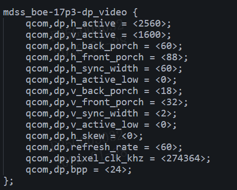
用您那边提供的诊断脚本读出来的寄存器状态如下所示:看着诊断结果983已经收到了soc传来的数据,但984接收不到983传来的数据,我们想知道这种情况怎么解决,麻烦尽快回复,谢谢!(py2_7) D:\files>python 7318.ALP_Ux98x_SERDES_Full_Diagnostics_V1.py
----------------------------------
Lock / Link Status
Ser Reg 0xC = 0x53 , Des Reg 0x53 = 0xa4 , Des Reg 0x54 = 0xc5 , Des Reg 0x4E = 0x5
Ser Reg 0xC = 0x53 , Des Reg 0x53 = 0xa4 , Des Reg 0x54 = 0xc5 , Des Reg 0x4E = 0x5
Ser Reg 0xC = 0x53 , Des Reg 0x53 = 0xa4 , Des Reg 0x54 = 0xc5 , Des Reg 0x4E = 0x5
Ser Reg 0xC = 0x53 , Des Reg 0x53 = 0xa4 , Des Reg 0x54 = 0xc5 , Des Reg 0x4E = 0x5
Ser Reg 0xC = 0x53 , Des Reg 0x53 = 0xa4 , Des Reg 0x54 = 0xc5 , Des Reg 0x4E = 0x5
Ser Reg 0xC = 0x53 , Des Reg 0x53 = 0xa4 , Des Reg 0x54 = 0xc5 , Des Reg 0x4E = 0x5
Ser Reg 0xC = 0x53 , Des Reg 0x53 = 0xa4 , Des Reg 0x54 = 0xc5 , Des Reg 0x4E = 0x5
Ser Reg 0xC = 0x53 , Des Reg 0x53 = 0xa4 , Des Reg 0x54 = 0xc5 , Des Reg 0x4E = 0x5
Ser Reg 0xC = 0x53 , Des Reg 0x53 = 0xa4 , Des Reg 0x54 = 0xc5 , Des Reg 0x4E = 0x5
Ser Reg 0xC = 0x53 , Des Reg 0x53 = 0xa4 , Des Reg 0x54 = 0xc5 , Des Reg 0x4E = 0x5
----------------------------------
VP Status
VP_STATUS: 3 , VP_INTERRUPTS: 25
VP_STATUS: 3 , VP_INTERRUPTS: 9
VP_STATUS: 3 , VP_INTERRUPTS: 9
VP_STATUS: 2 , VP_INTERRUPTS: 9
VP_STATUS: 2 , VP_INTERRUPTS: 9
VP_STATUS: 3 , VP_INTERRUPTS: 9
VP_STATUS: 3 , VP_INTERRUPTS: 9
VP_STATUS: 3 , VP_INTERRUPTS: 9
VP_STATUS: 2 , VP_INTERRUPTS: 9
VP_STATUS: 3 , VP_INTERRUPTS: 9
----------------------------------
DPRX Status
540 Rate
2 Lanes
0x377
0x0
0x4
0x0
Video source is set to SST mode
----------------------------------
H Res
2560
H POL
0
H SYNC WIDTH
60
H BACK PORCH
60
H TOTAL
2768
V Res
1600
V POL
0
V SYNC WIDTH
2
V BACK PORCH
18
HV TOTAL
1652
MSA_MISC0
33
MSA_MISC1
64
MSA_MVID
28260
MSA_NVID
55621
MSA_VBID
16
SYMBOL ERRORs - Lane 0
0x80000000L
SYMBOL ERRORs - Lane 1
0x80000000L
SYMBOL ERRORs - Lane 2
0x0
SYMBOL ERRORs - Lane 3
0x0
----------------------------------
DPTX Status
Page11 reg 0x93 = 0x0
No AUX Reply Detected
'DPCD addr 0x202 is 0xf4
'DPCD addr 0x203 is 0xb6
No AUX Reply Detected
'DPCD addr 0x202 is 0x80
'DPCD addr 0x203 is 0xb1
DPCD addr 0x100 is 0x93
DPCD addr 0x101 is 0x62
----------------------------------
Des FIFO = 0x0
----------------------------------
DTG Port 0 Timing:
Htotal = 0
Vtotal = 0
Hactive = 43905
Vactive = 0
Hstart = 0
Hsync = 11264
Vsync = 0
Vback = 0
Vfront = 0
----------------------------------
Print Des MSAs
('Port', 0, ': DPTX VIDEO RESOLUTION:')
('Port', 0, ': htotal (0x180) = 0')
('Port', 0, ': vtotal (0x184) = 0')
('Port', 0, ': hres (0x18C) = 0')
('Port', 0, ': vres (0x190) = 0')
('Port', 0, ': hstart (0x19C) = 0')
('Port', 0, ': vstart (0x1A0) = 0')
('Port', 0, ': hswidth (0x18C) = 0')
('Port', 0, ': vswidth (0x18C) = 0')
----------------------------------
Ux984 DPTX APBs
PORT 0 DPTX APB Dump: Main Stream Attributes
REG_000 (LINK_BW_SET) = 0
REG_004 (LANE_COUNT_SET) = 0
REG_008 (ENHANCED_FRAME_EN) = 1
REG_00C (TRAINING_PATTERN_SET) = 0
REG_010 (LINK_QUAL_PATTERN_SET) = 0
REG_014 (SCRAMBLING_DISABLE) = 0
REG_018 (DOWNSPREAD_CTRL) = 0
REG_01C (EDP_CAPABILITY_CONFIG) = 0
REG_020 (HBR2_COMPLIANCE_SCRAMBLER_RESET) = 0
REG_024 (DISPLAYPORT_VERSION) = 18
REG_024 (PHY_POWER_STATE) = 0
REG_02C (LANE_REMAP_CONTROL) = 0
REG_030 (CUSTOM_80BIT_PATTERN_0) = 0
REG_034 (CUSTOM_80BIT_PATTERN_1) = 0
REG_038 (CUSTOM_80BIT_PATTERN_2) = 0
REG_060 (FEC_ENABLE) = 0
REG_080 (TRANSMITTER_OUTPUT_ENABLE) = 0
REG_084 (VIDEO_STREAM_ENABLE) = 0
REG_088 (SECONDARY_STREAM_ENABLE) = 0
REG_088 (SECONDARY_DATA_WINDOW) = 128
REG_090 (SOFT_RESET) = 0
REG_094 (INPUT_SOURCE_ENABLE) = 0
REG_098 (FEC_ENABLE) = 0
REG_0C0 (ORCE_SCRAMBLER_RESET) = 0
REG_0C4 (USER_CONTROL_STATUS) = 0
REG_0C8 (USER_DATA_CONTROL) = 537141252
REG_0F8 (CORE_CAPABILITIES) = 5636
REG_0FC (CORE_ID) = 656648
REG_100 (AUX_COMMAND) = 2304
REG_104 (AUX_WRITE_FIFO) = 0
REG_108 (AUX_ADDRESS) = 257
REG_10C (AUX_CLOCK_DIVIDER) = 0
REG_110 (AUX_REPLY_TIMEOUT_INTERVAL) = 400
REG_128 (SINK_HPD_STATE) = 0
REG_130 (INTERRUPT_STATE) = 0
REG_134 (AUX_REPLY_DATA) = 18
REG_138 (AUX_REPLY_CODE) = 0
REG_13C (AUX_REPLY_COUNT) = 0
REG_140 (INTERRUPT_STATUS) = 0
REG_144 (INTERRUPT_MASK) = 63
REG_148 (REPLY_DATA_COUNT) = 0
REG_14C (AUX_STATUS) = 20
REG_150 (AUX_REPLY_CLOCK_WIDTH) = 0
REG_154 (AUX_WAKE_ACK_DETECTED) = 0
REG_158 (GP_HOST_TIMER) = 0
STREAM: 0 Register Read:
REG_0180 (MAIN_STREAM_HTOTAL) = 0
REG_0184 (MAIN_STREAM_VTOTAL) = 0
REG_0188 (MAIN_STREAM_POLARITY) = 0
REG_018C (MAIN_STREAM_HSWIDTH) = 0
REG_0190 (MAIN_STREAM_VSWIDTH) = 0
REG_0194 (MAIN_STREAM_HRES) = 0
REG_0198 (MAIN_STREAM_VRES) = 0
REG_019C (MAIN_STREAM_HSTART) = 0
REG_01A0 (MAIN_STREAM_VSTART) = 0
REG_01A4 (MAIN_STREAM_MISC0) = 0
REG_01A8 (MAIN_STREAM_MISC1) = 0
REG_01AC (MVID) = 0
REG_01B0 (TRANSFER_UNIT_CONFIG_SRC_0) = 64
REG_01B4 (NVID) = 0
REG_01B8 (USER_PIXEL_COUNT) = 1
REG_01BC (USER_DATA_COUNT) = 0
REG_01C0 (MAIN_STREAM_INTERLACED) = 0
REG_01C4 (USER_SYNC_POLARITY) = 15
REG_01C8 (USER_CONTROL) = 0
REG_01CC (USER_CONTROL) = 0
REG_0500 (MST_ENABLE) = 0
REG_0504 (MST_PID_TABLE_INDEX) = 0
REG_0508 (MST_PID_TABLE_ENTRY) = 0
REG_050C (SST_SOURCE_SELECT) = 0
REG_0510 (MST_ALLOCATION_TRIGGER) = 0
REG_0514 (MST_PID_TABLE_SELECT) = 0
REG_0518 (MST_ACTIVE_PAYLOAD_TABLE) = 0
REG_0520 (MST_ACTIVE) = 0
REG_0524 (MST_LINK_FRAME_COUNT) = 0
REG_0528 (MSO_CONFIGURATION) = 0
REG_0528 (MSO_CONFIGURATION) = 0
STREAM: 0 Register Read:
REG_0180 (MAIN_STREAM_HTOTAL) = 0
REG_0184 (MAIN_STREAM_VTOTAL) = 0
REG_0188 (MAIN_STREAM_POLARITY) = 0
REG_018C (MAIN_STREAM_HSWIDTH) = 2883584
REG_0190 (MAIN_STREAM_VSWIDTH) = 0
REG_0194 (MAIN_STREAM_HRES) = 0
REG_0198 (MAIN_STREAM_VRES) = 0
REG_019C (MAIN_STREAM_HSTART) = 0
REG_01A0 (MAIN_STREAM_VSTART) = 0
REG_01A4 (MAIN_STREAM_MISC0) = 0
REG_01A8 (MAIN_STREAM_MISC1) = 0
REG_01AC (MVID) = 0
REG_01B0 (TRANSFER_UNIT_CONFIG_SRC_0) = 64
REG_01B4 (NVID) = 0
REG_01B8 (USER_PIXEL_COUNT) = 11265
REG_01BC (USER_DATA_COUNT) = 0
REG_01C0 (MAIN_STREAM_INTERLACED) = 0
REG_01C4 (USER_SYNC_POLARITY) = 15
REG_01C8 (USER_CONTROL) = 0
REG_0500 (MST_ENABLE) = 0
REG_0504 (MST_PID_TABLE_INDEX) = 0
REG_0508 (MST_PID_TABLE_ENTRY) = 0
REG_050C (SST_SOURCE_SELECT) = 0
REG_0510 (MST_ALLOCATION_TRIGGER) = 0
REG_0514 (MST_PID_TABLE_SELECT) = 0
REG_0518 (MST_ACTIVE_PAYLOAD_TABLE) = 0
REG_0520 (MST_ACTIVE) = 0
REG_0524 (MST_LINK_FRAME_COUNT) = 0
REG_0528 (MSO_CONFIGURATION) = 0
REG_0528 (MSO_CONFIGURATION) = 0
-------------------------
Ux983_APB_dump
0x0 0x1
0x4 0x64
0x8 0x0
0xc 0x0
0x10 0x0
0x14 0x0
0x18 0x4
0x1c 0x14
0x20 0x0
0x24 0x0
0x28 0x33
0x2c 0x0
0x30 0x0
0x34 0x0
0x38 0x1
0x3c 0x0
0x40 0x0
0x44 0x70
0x48 0x0
0x4c 0x0
0x50 0x0
0x54 0x0
0x58 0x0
0x5c 0x0
0x60 0x0
0x64 0x0
0x68 0x0
0x6c 0x0
0x70 0xc0002
0x74 0x14
0x78 0x0
0x7c 0x0
0x80 0x1
0x84 0x0
0x88 0x0
0x8c 0x0
0x90 0x0
0x94 0x0
0x98 0x0
0x9c 0x0
0xa0 0x0
0xa4 0x0
0xa8 0x5
0xac 0x0
0xb0 0xc0000
0xb4 0x0
0xb8 0x0
0xbc 0x0
0xc0 0x0
0xc4 0x0
0xc8 0x0
0xcc 0x0
0xd0 0x0
0xd4 0x0
0xd8 0xc02
0xdc 0x0
0xe0 0x0
0xe4 0x0
0xe8 0x0
0xec 0x2
0xf0 0x0
0xf4 0x0
0xf8 0x123404
0xfc 0xb0507
0x100 0x0
0x104 0x0
0x108 0x0
0x10c 0x0
0x110 0x0
0x114 0x2
0x118 0x0
0x11c 0x0
0x120 0x0
0x124 0x0
0x128 0x0
0x12c 0x0
0x130 0x0
0x134 0x0
0x138 0x0
0x13c 0xc
0x140 0x0
0x144 0x0
0x148 0x0
0x14c 0x0
0x150 0x0
0x154 0x0
0x158 0x0
0x15c 0x0
0x160 0x0
0x164 0x0
0x168 0x0
0x16c 0x0
0x170 0x0
0x174 0x0
0x178 0x0
0x17c 0x0
0x180 0xfffffffeL
0x184 0x810
0x188 0x0
0x18c 0x310183
0x190 0x59
0x194 0x0
0x198 0x79
0x19c 0x0
0x1a0 0x7f
0x1a4 0x0
0x1a8 0x7f
0x1ac 0x0
0x1b0 0x0
0x1b4 0x0
0x1b8 0x0
0x1bc 0x0
0x1c0 0x0
0x1c4 0x0
0x1c8 0x0
0x1cc 0x0
0x1d0 0x0
0x1d4 0x0
0x1d8 0x0
0x1dc 0x0
0x1e0 0x0
0x1e4 0x0
0x1e8 0x0
0x1ec 0x0
0x1f0 0x0
0x1f4 0x0
0x1f8 0x0
0x1fc 0x0
0x200 0x0
0x204 0x0
0x208 0xf03f0
0x20c 0x0
0x210 0x0
0x214 0x2
0x218 0x0
0x21c 0x0
0x220 0x0
0x224 0x0
0x400 0x14
0x404 0x2
0x408 0x1
0x40c 0x0
0x410 0x0
0x414 0x0
0x418 0x0
0x41c 0x0
0x420 0x2
0x424 0x2
0x428 0x0
0x42c 0x0
0x430 0x0
0x434 0x1
0x438 0x1
0x43c 0x377
0x440 0x0
0x444 0x0
0x448 0x0
0x44c 0x0
0x450 0x0
0x454 0x1010000
0x458 0x0
0x45c 0x0
0x460 0x0
0x464 0x0
0x468 0x0
0x46c 0x0
0x470 0x0
0x474 0x0
0x478 0x0
0x47c 0x0
0x480 0x0
0x484 0x3f3f
0x488 0x0
0x48c 0x0
0x490 0x80000000L
0x494 0x80000000L
0x498 0x0
0x49c 0x0
0x4a0 0x0
0x4a4 0x0
0x4a8 0x0
0x4ac 0x0
0x4b0 0x0
0x4b4 0x0
0x4b8 0x0
0x4bc 0x0
0x4c0 0x0
0x4c4 0x0
0x4c8 0x0
0x4cc 0x0
0x4d0 0x0
0x4d4 0x0
0x4d8 0x0
0x4dc 0x0
0x4e0 0x0
0x4e4 0x0
0x4e8 0x0
0x4ec 0x0
0x4f0 0x0
0x4f4 0x0
0x4f8 0x0
0x4fc 0x0
0x500 0xa00
0x504 0x0
0x508 0x3c
0x50c 0x78
0x510 0xad0
0x514 0x640
0x518 0x0
0x51c 0x2
0x520 0x14
0x524 0x674
0x528 0x21
0x52c 0x40
0x530 0x6e64
0x534 0xd945
0x538 0x10
0x53c 0x0
0x700 0x0
0x704 0x0
0x708 0x0
0x70c 0x0
0x710 0x0
0x714 0x0
0x718 0x0
0x71c 0x0
0x720 0x0
0x800 0x0
0x804 0x0
0x808 0x0
0x80c 0x0
0x810 0x0
0x814 0x270
0x818 0x0
0x81c 0x2
0x820 0x90
0x824 0x270
0x828 0x0
0x82c 0x0
0x830 0x0
0x834 0x0
0x838 0x0
0x83c 0x0
0x840 0x0
0x844 0x0
0x848 0x0
0x84c 0x0
0x850 0x0
0x854 0x0
0x858 0x0
0x85c 0x0
0x860 0x0
0x864 0x0
0x868 0x0
0x86c 0x0
0x870 0x0
0x874 0x0
0x878 0x0
0x87c 0x0
0x880 0x0
0x884 0x0
0x888 0x0
0x88c 0x0
0x890 0x0
0x894 0x0
0x898 0x0
0x89c 0x0
0x8a0 0x0
0x8a4 0x0
0x8a8 0x0
0x8ac 0x0
0x8b0 0x0
0x8b4 0x0
0x8b8 0x0
0x8bc 0x0
0x8c0 0x0
0x8c4 0x0
0x8c8 0x0
0x8cc 0x0
0x8d0 0x0
0x8d4 0x0
0x8d8 0x0
0x8dc 0x0
0x8e0 0x0
0x8e4 0x0
0x8e8 0x0
0x8ec 0x0
0x8f0 0x0
0x8f4 0x0
0x8f8 0x0
0x8fc 0x0
0x900 0x0
0x904 0x0
0x908 0x0
0x90c 0x0
0x910 0x0
0x914 0x0
0x918 0x0
0x91c 0x0
0x920 0x0
0x924 0x0
0x928 0x0
0x92c 0x0
0x930 0x0
0x934 0x0
0xa00 0x1
0xa04 0xc04
0xa08 0x0
0xa0c 0x0
0xa10 0x0
0xa14 0xc
0xa18 0x5
0xa1c 0x8
0xa20 0xf
0xa24 0x1ff003f
0xa28 0x20
0xa2c 0x0
0xa30 0x78
0xa34 0x0
0xa38 0x0
0xa3c 0x0
0xa40 0x0
0xa44 0x0
0xa48 0x0
0xa4c 0x0
0xa50 0x0
0xa54 0x0
0xa58 0x0
0xa5c 0x0
0xa60 0x0
0xa64 0x0
0xa68 0x0
0xa6c 0x0
0xa70 0x0
0xa74 0x0
0xa78 0x0
0xa7c 0x0
0xa80 0x1
0xa84 0x0
0xa88 0x0
0xa8c 0x18
0xa90 0x4
0xa94 0x0
0xa98 0x0
0xa9c 0x76543210
0xaa0 0x0
0xaa4 0x0
0xaa8 0x0
0xaac 0x0
0xab0 0xc
0xab4 0x1
0xab8 0x0
0xabc 0x0
0xac0 0x0
0xac4 0x0
0xac8 0x0
0xacc 0x0
0xad0 0x0
0xad4 0x0
0xad8 0x0
0xadc 0x0
0xae0 0x0
0xae4 0x0
0xae8 0x2
0xaec 0x0
0xaf0 0x0
0xaf4 0x0
0xaf8 0x0
0xafc 0x0
0xb00 0x0
0xb04 0x4
0xb08 0x0
0xb0c 0x0
0xb10 0x0
0xb14 0x0
0xb18 0x0
0xb1c 0x8
0xb20 0xf
0xb24 0x1ff003f
0xb28 0xf000f
0xb2c 0x0
0xb30 0x78
0xb34 0x0
0xb38 0x0
0xb3c 0xc
0xb40 0x0
0xb44 0xc
0xb48 0x0
0xb4c 0x0
0xb50 0x0
0xb54 0x0
0xb58 0x0
0xb5c 0x0
0xb60 0x0
0xb64 0x0
0xb68 0x0
0xb6c 0x0
0xb70 0x0
0xb74 0x0
0xb78 0x0
0xb7c 0x0
0xb80 0x0
0xb84 0x1
0xb88 0x0
0xb8c 0x0
0xb90 0x0
0xb94 0x0
0xb98 0x0
0xb9c 0x0
0xba0 0x0
0xba4 0x0
0xba8 0x0
0xbac 0x0
0xbb0 0x0
0xbb4 0x0
0xbb8 0x0
0xbbc 0x0
0xbc0 0x0
0xbc4 0x0
0xbc8 0x0
0xbcc 0x0
0xbd0 0x0
0xbd4 0x0
0xbd8 0x0
0xbdc 0x0
0xbe0 0x0
