DS90UB941AS-Q1: The image cannot be shifted upward to fully cover the entire screen

Part Number: DS90UB941AS-Q1
Other Parts Discussed in Thread: DS90UB928Q-Q1

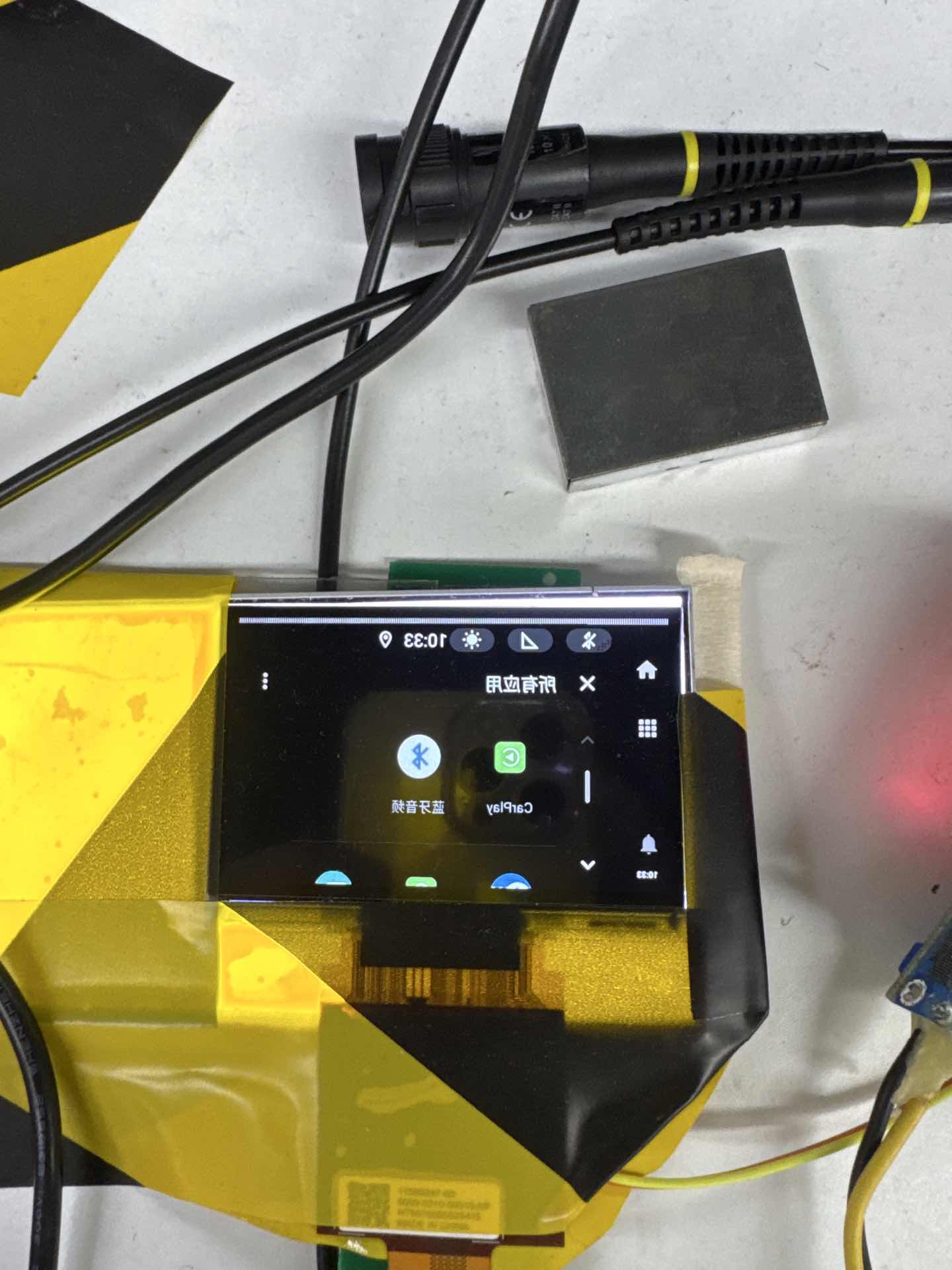
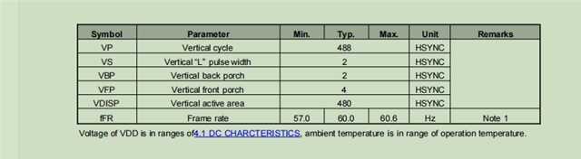
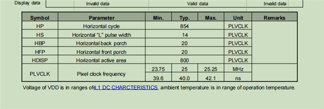
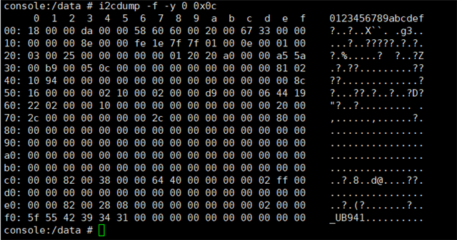
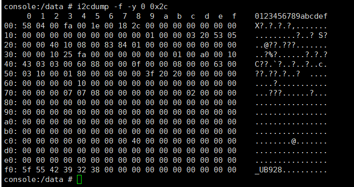
We have a project using the ds90ub941as-q1 and ds90ub928q-q1 chips. Despite repeated debugging of screen parameters on the SoC side, the image cannot be shifted upward to fully cover the entire screen (as shown in the attached document). Is there a debugging solution related to the Serializer/Deserializer (SerDes) registers to address this issue?63a2d0b2acba6ad8ec6121f0860a92e.jpg 

  • 你好

    已经收到了您的案例,调查需要些时间,感谢您的耐心等待

  • Hi 

    Thank you for attaching the image of the issue. We will need to first identify if this screen shifting is related to the SERDES or the DSI input. The UB941AS has a PATGEN that we can use to send over a pattern to see if there are still issues on the screen. I will need the video timing information for the display in order to make a script for this.

    Can we also get the following information to understand the customer's configuration and system?

    • What are the DSI configurations?
      • Continuous clock or non-continuous clock?
      • Sync pulses or sync events?
    • What are the UB941AS configurations?
      • Using DSI reference clock?
      • Register dump of the UB941AS
  •  I will need the video timing information for the display
    reply:


    "Continuous clock or non-continuous clock?"
    reply:Continuous clock

    "Sync pulses or sync events?"
    reply:Sync pulses

    What are the UB941AS configurations?
    rely:
    UB941AS configurations:
    i2cset -f -y 0 0x0c 0x01 0x02 w
    i2cset -f -y 0 0x0c 0x01 0x08 w
    i2cset -f -y 0 0x0c 0x1E 0x01 w
    i2cset -f -y 0 0x0c 0x06 0x2c w
    i2cset -f -y 0 0x0c 0x07 0x60 w
    i2cset -f -y 0 0x0c 0x08 0x60 w
    i2cset -f -y 0 0x0c 0x70 0x2c w
    i2cset -f -y 0 0x0c 0x77 0x2c w
    i2cset -f -y 0 0x0c 0x1E 0x01 w
    i2cset -f -y 0 0x0c 0x04 0x10 w
    i2cset -f -y 0 0x0c 0x03 0xDA w
    i2cset -f -y 0 0x0c 0x4F 0x8C w
    i2cset -f -y 0 0x0c 0x5B 0x00 w
    i2cset -f -y 0 0x0c 0x01 0x00 w
    i2cset -f -y 0 0x0c 0x0e 0x33 w
    i2cset -f -y 0 0x0c 0x0d 0x03 w

    UB928AS configurations:
    i2cset -f -y 0 0x2c 0x03 0xfa w
    i2cset -f -y 0 0x2c 0x08 0x2c w
    i2cset -f -y 0 0x2c 0x1e 0x53 w
    i2cset -f -y 0 0x2c 0x1f 0x05 w

    Using DSI reference clock?
    reply:yes.
    Register dump of the UB941AS:


    Register dump of the UB928AS:


  • 您好

    Thank you for the detailed response. From the register dump, I noted the following

    • Lock is established
    • FPD-Link III Single Port 0 Mode
    • DSI PCLK Frequency = 25MHz
    • DSI frequency is stable

    Is the DSI TX operating in burst mode or non-burst mode?

    There are some missing configurations in the UB941AS. These might not be the root cause of the shifted screen but are needed for stable operation

    UB941AS configurations:
    i2cset -f -y 0 0x0c 0x01 0x02 w // Hard reset 941AS
    // Insert 40ms delay after soft reset or hard reset ***
    i2cset -f -y 0 0x0c 0x01 0x08 w // Disable 941AS DSI RX
    i2cset -f -y 0 0x0c 0x1E 0x01 w
    i2cset -f -y 0 0x0c 0x06 0x2c w
    i2cset -f -y 0 0x0c 0x07 0x60 w
    i2cset -f -y 0 0x0c 0x08 0x60 w
    i2cset -f -y 0 0x0c 0x70 0x2c w
    i2cset -f -y 0 0x0c 0x77 0x2c w
    i2cset -f -y 0 0x0c 0x1E 0x01 w
    i2cset -f -y 0 0x0c 0x04 0x10 w
    i2cset -f -y 0 0x0c 0x03 0xDA w
    i2cset -f -y 0 0x0c 0x4F 0x8C w
    i2cset -f -y 0 0x0c 0x5B 0x00 w
    
    // Set DSI Port 0 TSKIP (941AS datasheet 8.3.1.2)
    i2cset -f -y 0 0x0c 0x40 0x04 w
    i2cset -f -y 0 0x0c 0x41 0x05 w
    i2cset -f -y 0 0x0c 0x42 0x00 w
    
    // Initialize internal DSI clock settings (941AS datasheet 10.2)
    i2cset -f -y 0 0x0c 0x40 0x10 w
    i2cset -f -y 0 0x0c 0x41 0x86 w
    i2cset -f -y 0 0x0c 0x42 0x0A w
    i2cset -f -y 0 0x0c 0x41 0x94 w
    i2cset -f -y 0 0x0c 0x42 0x0A w
    
    i2cset -f -y 0 0x0c 0x01 0x00 w // Enable 941AS DSI RX
    i2cset -f -y 0 0x0c 0x0e 0x33 w
    i2cset -f -y 0 0x0c 0x0d 0x03 w

    See below script for UB941AS PATGEN with internal timings.

    serAddr = 0x18
    
    board.WriteI2C(serAddr, 0x64, 0x00)    #   Disable PATGEN
    board.WriteI2C(serAddr, 0x66, 0x03)
    board.WriteI2C(serAddr, 0x67, 0x40)    #   PATGEN_CDIV_N		
    board.WriteI2C(serAddr, 0x66, 0x04)		
    board.WriteI2C(serAddr, 0x67, 0x56)    #	THW_7:0
    board.WriteI2C(serAddr, 0x66, 0x05)		
    board.WriteI2C(serAddr, 0x67, 0x83)    #	TVW_3:0
    board.WriteI2C(serAddr, 0x66, 0x06)		
    board.WriteI2C(serAddr, 0x67, 0x1E)    #	TVW_11:4
    board.WriteI2C(serAddr, 0x66, 0x07)		
    board.WriteI2C(serAddr, 0x67, 0x20)    #	AHW_7:0
    board.WriteI2C(serAddr, 0x66, 0x08)		
    board.WriteI2C(serAddr, 0x67, 0x03)    #	AVW_3:0
    board.WriteI2C(serAddr, 0x66, 0x09)		
    board.WriteI2C(serAddr, 0x67, 0x1E)    #	AVW_11:4
    board.WriteI2C(serAddr, 0x66, 0x0A)		
    board.WriteI2C(serAddr, 0x67, 0x0E)    #	HSW_7:0
    board.WriteI2C(serAddr, 0x66, 0x0B)		
    board.WriteI2C(serAddr, 0x67, 0x02)    #	VSW_7:0
    board.WriteI2C(serAddr, 0x66, 0x0C)	
    board.WriteI2C(serAddr, 0x67, 0x14)    #	HBP
    board.WriteI2C(serAddr, 0x66, 0x0D)		
    board.WriteI2C(serAddr, 0x67, 0x02)    #	VBP
    board.WriteI2C(serAddr, 0x66, 0x0E)		
    board.WriteI2C(serAddr, 0x67, 0x03)    #	VS_POL, HS_POL
    board.WriteI2C(serAddr, 0x66, 0x1A)
    board.WriteI2C(serAddr, 0x67, 0x02)    #   PATGEN_CDIV_M
    board.WriteI2C(serAddr, 0x65, 0x04)    #   Internal timing
    board.WriteI2C(serAddr, 0x64, 0x05)	   #   Enable PATGEN with color bars