Other Parts Discussed in Thread: ALP, DS90UB949A-Q1
Hello Sir:
I got the DS90UB949 EVM recently, I want to setup the HDMI to FPDLink3 on this board.
[input/output]
My HDMI source is My PC.
FPD Link 3 output is a display with deserializer. (it works well).
[preparation]
I connect this board with Mini USB , (set J33 to get power with USB , the LED on boad turn on ).
the S1, S2, S3, S6 are also with default setting.
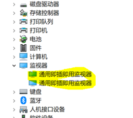
I check HDMI info in the device manager in my windows 10. my windows 10 can recognize the second monitor in the list.
there is no extral EEPROM on the EVM board.
[My target]
I only want to translate HDMI input to the FPD Link3 output. (the output resoluation is 1280x640)
[My Queston ]
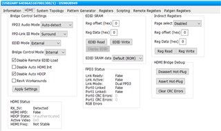
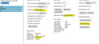
Q1: While create new profile from exist profile, there is a tab for EEPROM , What is this EEROM used for? what should input in this part?
Q2: How to write EDID infomation to the EVM board?
Q2.1: there is 4 methods for EDID in user guide, ( I don't have extra EEROM on my board. ) Which one should I select? Can I modify the Internal pre-programed EDID ?
• External local EDID (EEPROM)
• Internal EDID loaded into device memory
• Remote EDID connected to I2C bus at deserializer side
• Internal pre-programmed EDI
Q2.2: How can I write the EDID infomation into baord?
I saw the pdf document (949-929 Read-Write EDID.pdf) to discritp how to read/write EDID, but the EDID infomation is genrated by other tool (e.g. Deltacase-EDID ), how to select the EDID file and wirte inoto board?
there are only " EDID Read"/" EDID Write" on the HDMI tab of ALP .
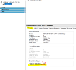
Q3: the infomation on ALP is list below, Can you help to check if there other problem on my configration?
Infomation tab of ALP : ( althogh it is link with line and usb)
Current Link Status:
Link to Deserializer : No
Link to HDMI source : No