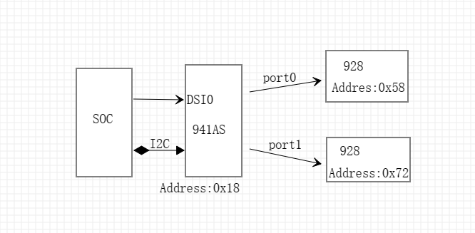
在gpio寄存器设置了gpio0和gpio1,port0映射成功了,但port1映射失败,是什么原因呢?

This thread has been locked.
If you have a related question, please click the "Ask a related question" button in the top right corner. The newly created question will be automatically linked to this question.
您好,您的这个问题和上一个帖子类似,上一个帖子是主机找不到port1的device地址,所以也就无法访问928。
可以把941的配置附上看下,主要这几个寄存器0x5B(配置输出模式),0x4F(配置 DSI input /output lane),0x1E(enable port1)。
你好,配置如下:
I2C_Write(DS90UH941AS_ADDR,0x1E,0x04,I2C_FMT_A8D8);
//PORT1->928
I2C_Write(DS90UB928Q1_RIGHT_ADDR,0x1D,0x05,I2C_FMT_A8D8); //GPIO0
I2C_Write(DS90UB928Q1_RIGHT_ADDR,0x1E,0x05,I2C_FMT_A8D8); //GPIO1
I2C_Write(DS90UH941AS_ADDR,0x1E,0x01,I2C_FMT_A8D8); //Select FPD-Link III Port 0
I2C_Write(DS90UH941AS_ADDR,0x4F,0x8C,I2C_FMT_A8D8); //Set DSI_CONTINUOUS_CLOCK, 4 lanes, DSI Port 0
I2C_Write(DS90UH941AS_ADDR,0x5B,0x07,I2C_FMT_A8D8); //Force Splitter mode
I2C_Write(DS90UH941AS_ADDR,0x56,0x80,I2C_FMT_A8D8); //Enable Video L/R 3D
I2C_Write(DS90UH941AS_ADDR,0x32,0x00,I2C_FMT_A8D8); //Set the line size to 1280(LSB)
I2C_Write(DS90UH941AS_ADDR,0x33,0x05,I2C_FMT_A8D8); //Set the line size to 1280 (MSB)
//Port 0
I2C_Write(DS90UH941AS_ADDR,0x1E,0x01,I2C_FMT_A8D8); //Select FPD-Link III Port 0
I2C_Write(DS90UH941AS_ADDR,0x04,0x20,I2C_FMT_A8D8); //Clear CRCERR|Enable DE
I2C_Write(DS90UH941AS_ADDR,0x36,0x00,I2C_FMT_A8D8); //Set crop start X position to 0 (LSB)
I2C_Write(DS90UH941AS_ADDR,0x37,0x80,I2C_FMT_A8D8); //Set crop start X position to 0 (MSB) and enable cropping
I2C_Write(DS90UH941AS_ADDR,0x38,0xFF,I2C_FMT_A8D8); //Set crop stop X position to 1279 (LSB)
I2C_Write(DS90UH941AS_ADDR,0x39,0x04,I2C_FMT_A8D8); //Set crop stop X position to 1279 (MSB)
I2C_Write(DS90UH941AS_ADDR,0x3A,0x00,I2C_FMT_A8D8); //Set crop start Y position to 0 (LSB)
I2C_Write(DS90UH941AS_ADDR,0x3B,0x00,I2C_FMT_A8D8); //Set crop start Y position to 0 (MSB)
I2C_Write(DS90UH941AS_ADDR,0x3C,0xFF,I2C_FMT_A8D8); //Set crop stop Y position to 767 (LSB)
I2C_Write(DS90UH941AS_ADDR,0x3D,0x02,I2C_FMT_A8D8); //Set crop stop Y position to 767 (MSB)
//Port 1
I2C_Write(DS90UH941AS_ADDR,0x1E,0x02,I2C_FMT_A8D8); //Select FPD-Link III Port 1
I2C_Write(DS90UH941AS_ADDR,0x36,0x00,I2C_FMT_A8D8); //Set crop start X position to 0 (LSB)
I2C_Write(DS90UH941AS_ADDR,0x37,0x80,I2C_FMT_A8D8); //Set crop start X position to 0 (MSB) and enable cropping
I2C_Write(DS90UH941AS_ADDR,0x38,0xFF,I2C_FMT_A8D8); //Set crop stop X position to 1279 (LSB)
I2C_Write(DS90UH941AS_ADDR,0x39,0x04,I2C_FMT_A8D8); //Set crop stop X position to 1279 (MSB)
I2C_Write(DS90UH941AS_ADDR,0x3A,0x00,I2C_FMT_A8D8); //Set crop start Y position to 0 (LSB)
I2C_Write(DS90UH941AS_ADDR,0x3B,0x00,I2C_FMT_A8D8); //Set crop start Y position to 0 (MSB)
I2C_Write(DS90UH941AS_ADDR,0x3C,0xFF,I2C_FMT_A8D8); //Set crop stop Y position to 767 (LSB)
I2C_Write(DS90UH941AS_ADDR,0x3D,0x02,I2C_FMT_A8D8); //Set crop stop Y position to 767 (MSB)
//Program TSKIP_CNT DSI parameter on DSI Port0
I2C_Write(DS90UH941AS_ADDR,0x40,0x04,I2C_FMT_A8D8); //Select DSI Port 0 digital registers
I2C_Write(DS90UH941AS_ADDR,0x41,0x05,I2C_FMT_A8D8); //Select DPHY_SKIP_TIMING register
I2C_Write(DS90UH941AS_ADDR,0x42,0x14,I2C_FMT_A8D8); //Write TSKIP_CNT value for 488 MHz DSI clock frequency
I2C_Write(DS90UH941AS_ADDR,0x01,0x00,I2C_FMT_A8D8); //Enable DSI
I2C_Write(DS90UH941AS_ADDR,0x1E,0x01,I2C_FMT_A8D8); //Select FPD-Link III Port 0
I2C_Write(DS90UH941AS_ADDR,0x0E,0x03,I2C_FMT_A8D8); //GPIO1
I2C_Write(DS90UH941AS_ADDR,0x0D,0x03,I2C_FMT_A8D8); //GPIO0
I2C_Write(DS90UH941AS_ADDR,0x1E,0x02,I2C_FMT_A8D8); //Select FPD-Link III Port 1
I2C_Write(DS90UH941AS_ADDR,0x0E,0x03,I2C_FMT_A8D8); //GPIO1
I2C_Write(DS90UH941AS_ADDR,0x0D,0x03,I2C_FMT_A8D8); //GPIO0
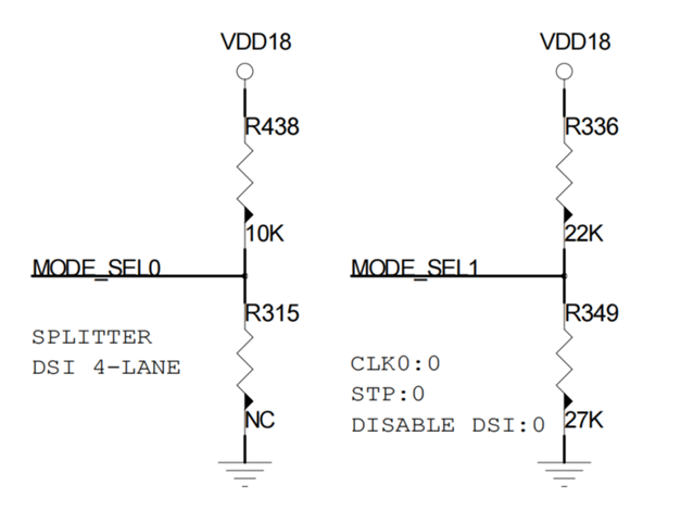
您好,我看了主要的寄存器,已经配置成splitter mode了,但是0x4F和0X5B的寄存器默认的是MODE_SEL0 的配置,所以检查下MODE_SEL0 的上下拉电阻是否配置的splitter mode。
另外读取下0x13的值,确认下MODE_SEL0 是否已经稳定。
另外,您也可以参考下这篇关于配置成splitter mode的FAQ:

0x13寄存器的值为:I2C_Read TX_MODE_STS:0xCF
没发现什么问题
您好,试试下面的配置。
Write 941AS reg 0x1E = 0x01 to select port 0
Write 941AS reg 0x03 = 0x9A to enable I2C passthrough on port 0
Write 948 reg 0x00 = 0x5D to override the address of the 948 on port 0 to 0x2E
Write 941AS reg 0x1E = 0x02 to select port 0
Write 941AS reg 0x03 = 0x9A to enable I2C passthrough on port 1
Write 941AS reg 0x1E = 0x03 to select both ports
这样设置没有用,论坛上所有的贴都看过了,没找到答案,你发的这个也看过了,所以还是从根本上找下到底什么原因!
您是如何判断不能读取port1 的地址的?先这样试试:选择port0读取下和Port0连接的948的地址是否能读到?
同样再选择port1,然后再去读Port1连接的地址0x06.看下0x06是什么值?是否能读取到和port1 连接的948的地址是否能读到。
也就是下面的步骤试试:
Set 0x1E = 0x01
Read 0x06 - read this register to check what is the value.
Set 0x1E = 0x02
Read 0x06 - read this register to check what is the value.
顺祝,中秋国庆双节快乐
你好,祝中秋国庆双节快乐
读06寄存器的地址都是正常的,我的意思是:通过941都可以访问port0和port1上的928,941可以映射gpio到port0上,即941的gpio0输入pwm,928的gpio0也会输出pwm,现在的问题是,941的gpio不能映射到port1上的928,也就是941的gpio0输入pwm,port1上的928 gpio0一直没有任何变化。
您的问题我在跟进中,需要点儿时间,会尽快给您回复。
I2C_Write(DS90UH941AS_ADDR,0x1E,0x01,I2C_FMT_A8D8); //Select FPD-Link III Port 0
I2C_Write(DS90UH941AS_ADDR,0x0E,0x03,I2C_FMT_A8D8); //GPIO1
I2C_Write(DS90UH941AS_ADDR,0x0D,0x03,I2C_FMT_A8D8); //GPIO0I2C_Write(DS90UH941AS_ADDR,0x1E,0x02,I2C_FMT_A8D8); //Select FPD-Link III Port 1
I2C_Write(DS90UH941AS_ADDR,0x0E,0x03,I2C_FMT_A8D8); //GPIO1
I2C_Write(DS90UH941AS_ADDR,0x0D,0x03,I2C_FMT_A8D8); //GPIO0
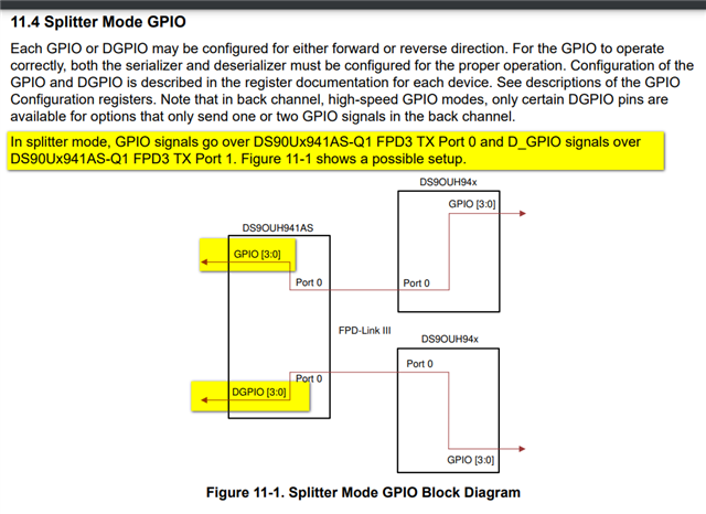
您好,抱歉回复晚了,我看了下GPIO的定义,port0这里的GPIO透传是没问题的,应该是port1这里的问题,当0x1E选择port1的时候,PWM信号应该是通过D_GPIO0传输,然后再配置0x0E和0x0D,port1上的928 gpio0应该才是变化的
看下数据手册关于GPIO的定于,当Port1被选择的时候,GPIO0控制的是D_GPIO0 pin。

另外,在941AS splitter mode应用手册中关于GPIO部分的介绍。GPIO信号传输的是TX port0,D_GPIO传输的才是TX port1.如图Figure11-1。

我现在就是这样操作的,选择port1是就是操作D_GPIO,但port1的928 GPIO没有任何反应
那配置应该是没有问题的,有没有检查硬件,或者更换一片DS90UB928试试?
换板子都是一样的,就是想确认下,芯片能不能同时映射port0和port1的,如果可以的话为什么port1映射不成功呢。按照手册就是选择port1后,设置和port0一样的
您好,这个问题时间比较久了,我需要再花点儿时间看下这个问题,周一给您答复。