If you have a related question, please click the "Ask a related question" button in the top right corner. The newly created question will be automatically linked to this question.
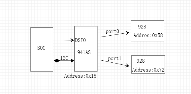
I2C_Write(DS90UH941AS_ADDR,0x1E,0x01,I2C_FMT_A8D8); //Select FPD-Link III Port 0 I2C_Write(DS90UH941AS_ADDR,0x4F,0x8C,I2C_FMT_A8D8); //Set DSI_CONTINUOUS_CLOCK, 4 lanes, DSI Port 0
I2C_Write(DS90UH941AS_ADDR,0x5B,0x07,I2C_FMT_A8D8); //Force Splitter mode I2C_Write(DS90UH941AS_ADDR,0x56,0x80,I2C_FMT_A8D8); //Enable Video L/R 3D I2C_Write(DS90UH941AS_ADDR,0x32,0x00,I2C_FMT_A8D8); //Set the line size to 1280(LSB) I2C_Write(DS90UH941AS_ADDR,0x33,0x05,I2C_FMT_A8D8); //Set the line size to 1280 (MSB)
//Port 0 I2C_Write(DS90UH941AS_ADDR,0x1E,0x01,I2C_FMT_A8D8); //Select FPD-Link III Port 0 I2C_Write(DS90UH941AS_ADDR,0x04,0x20,I2C_FMT_A8D8); //Clear CRCERR|Enable DE I2C_Write(DS90UH941AS_ADDR,0x36,0x00,I2C_FMT_A8D8); //Set crop start X position to 0 (LSB) I2C_Write(DS90UH941AS_ADDR,0x37,0x80,I2C_FMT_A8D8); //Set crop start X position to 0 (MSB) and enable cropping I2C_Write(DS90UH941AS_ADDR,0x38,0xFF,I2C_FMT_A8D8); //Set crop stop X position to 1279 (LSB) I2C_Write(DS90UH941AS_ADDR,0x39,0x04,I2C_FMT_A8D8); //Set crop stop X position to 1279 (MSB) I2C_Write(DS90UH941AS_ADDR,0x3A,0x00,I2C_FMT_A8D8); //Set crop start Y position to 0 (LSB) I2C_Write(DS90UH941AS_ADDR,0x3B,0x00,I2C_FMT_A8D8); //Set crop start Y position to 0 (MSB) I2C_Write(DS90UH941AS_ADDR,0x3C,0xFF,I2C_FMT_A8D8); //Set crop stop Y position to 767 (LSB) I2C_Write(DS90UH941AS_ADDR,0x3D,0x02,I2C_FMT_A8D8); //Set crop stop Y position to 767 (MSB)
//Port 1 I2C_Write(DS90UH941AS_ADDR,0x1E,0x02,I2C_FMT_A8D8); //Select FPD-Link III Port 1 I2C_Write(DS90UH941AS_ADDR,0x36,0x00,I2C_FMT_A8D8); //Set crop start X position to 0 (LSB) I2C_Write(DS90UH941AS_ADDR,0x37,0x80,I2C_FMT_A8D8); //Set crop start X position to 0 (MSB) and enable cropping I2C_Write(DS90UH941AS_ADDR,0x38,0xFF,I2C_FMT_A8D8); //Set crop stop X position to 1279 (LSB) I2C_Write(DS90UH941AS_ADDR,0x39,0x04,I2C_FMT_A8D8); //Set crop stop X position to 1279 (MSB) I2C_Write(DS90UH941AS_ADDR,0x3A,0x00,I2C_FMT_A8D8); //Set crop start Y position to 0 (LSB) I2C_Write(DS90UH941AS_ADDR,0x3B,0x00,I2C_FMT_A8D8); //Set crop start Y position to 0 (MSB) I2C_Write(DS90UH941AS_ADDR,0x3C,0xFF,I2C_FMT_A8D8); //Set crop stop Y position to 767 (LSB) I2C_Write(DS90UH941AS_ADDR,0x3D,0x02,I2C_FMT_A8D8); //Set crop stop Y position to 767 (MSB)
//Program TSKIP_CNT DSI parameter on DSI Port0 I2C_Write(DS90UH941AS_ADDR,0x40,0x04,I2C_FMT_A8D8); //Select DSI Port 0 digital registers I2C_Write(DS90UH941AS_ADDR,0x41,0x05,I2C_FMT_A8D8); //Select DPHY_SKIP_TIMING register I2C_Write(DS90UH941AS_ADDR,0x42,0x14,I2C_FMT_A8D8); //Write TSKIP_CNT value for 488 MHz DSI clock frequency I2C_Write(DS90UH941AS_ADDR,0x01,0x00,I2C_FMT_A8D8); //Enable DSI
I2C_Write(DS90UH941AS_ADDR,0x1E,0x01,I2C_FMT_A8D8); //Select FPD-Link III Port 0