
请注意,本文内容源自机器翻译,可能存在语法或其它翻译错误,仅供参考。如需获取准确内容,请参阅链接中的英语原文或自行翻译。
器件型号:TM4C1290NCZAD 主题中讨论的其他器件: DK-TM4C129X
我正在尝试使用 TM4C1290NCZAD 使 UART_Echo 程序在我们的电路板上正常工作。
我从 TI 获得了 UART0的代码。
但我使用的是 UART5。 但它不起作用。
是否有适用于 TM4C1290的任何其他 UART 代码?
谢谢
km

This thread has been locked.
If you have a related question, please click the "Ask a related question" button in the top right corner. The newly created question will be automatically linked to this question.
我正在尝试使用 TM4C1290NCZAD 使 UART_Echo 程序在我们的电路板上正常工作。
我从 TI 获得了 UART0的代码。
但我使用的是 UART5。 但它不起作用。
是否有适用于 TM4C1290的任何其他 UART 代码?
谢谢
km
您好 Kiran、
我想它只是初始化方面的一个小错误、它会一直发生、甚至对我们来说。 您能否发布 UART 代码以便我可以查看它?
此致、
Ralph Jacobi
//*****************************************************************************
//
// uart_echo.c - Example for reading data from and writing data to the UART in
//               an interrupt driven fashion.
//
// Copyright (c) 2013-2017 Texas Instruments Incorporated.  All rights reserved.
// Software License Agreement
//
// Texas Instruments (TI) is supplying this software for use solely and
// exclusively on TI's microcontroller products. The software is owned by
// TI and/or its suppliers, and is protected under applicable copyright
// laws. You may not combine this software with "viral" open-source
// software in order to form a larger program.
//
// THIS SOFTWARE IS PROVIDED "AS IS" AND WITH ALL FAULTS.
// NO WARRANTIES, WHETHER EXPRESS, IMPLIED OR STATUTORY, INCLUDING, BUT
// NOT LIMITED TO, IMPLIED WARRANTIES OF MERCHANTABILITY AND FITNESS FOR
// A PARTICULAR PURPOSE APPLY TO THIS SOFTWARE. TI SHALL NOT, UNDER ANY
// CIRCUMSTANCES, BE LIABLE FOR SPECIAL, INCIDENTAL, OR CONSEQUENTIAL
// DAMAGES, FOR ANY REASON WHATSOEVER.
//
// This is part of revision 2.1.4.178 of the DK-TM4C129X Firmware Package.
//
//*****************************************************************************

#include <stdint.h>
#include <stdbool.h>
#include "inc/hw_ints.h"
#include "inc/hw_memmap.h"
#include "inc/hw_types.h"
#include "driverlib/debug.h"
#include "driverlib/gpio.h"
#include "driverlib/interrupt.h"
#include "driverlib/sysctl.h"
#include "driverlib/uart.h"
#include "driverlib/rom.h"
#include "driverlib/rom_map.h"
#include "grlib/grlib.h"
#include "drivers/kentec320x240x16_ssd2119.h"
#include "drivers/frame.h"
#include "drivers/pinout.h"

//*****************************************************************************
//
//! \addtogroup example_list
//! <h1>UART Echo (uart_echo)</h1>
//!
//! This example application utilizes the UART to echo text.  The first UART
//! (connected to the FTDI virtual serial port on the evaluation board) will be
//! configured in 115,200 baud, 8-n-1 mode.  All characters received on the
//! UART are transmitted back to the UART.
//
//*****************************************************************************

//*****************************************************************************
//
// The error routine that is called if the driver library encounters an error.
//
//*****************************************************************************
#ifdef DEBUG
void
__error__(char *pcFilename, uint32_t ui32Line)
{
}
#endif

//*****************************************************************************
//
// The UART interrupt handler.
//
//*****************************************************************************
void
UARTIntHandler(void)
{
    uint32_t ui32Status;

    //
    // Get the interrrupt status.
    //
    ui32Status = ROM_UARTIntStatus(UART5_BASE, true);

    //
    // Clear the asserted interrupts.
    //
    ROM_UARTIntClear(UART5_BASE, ui32Status);

    //
    // Loop while there are characters in the receive FIFO.
    //
    while(ROM_UARTCharsAvail(UART5_BASE))
    {
        //
        // Read the next character from the UART and write it back to the UART.
        //
        ROM_UARTCharPutNonBlocking(UART5_BASE,
                                   UARTCharGetNonBlocking(UART5_BASE));
    }
}

//*****************************************************************************
//
// Send a string to the UART.
//
//*****************************************************************************
void
UARTSend(const uint8_t *pui8Buffer, uint32_t ui32Count)
{
    //
    // Loop while there are more characters to send.
    //
    while(ui32Count--)
    {
        //
        // Write the next character to the UART.
        //
        ROM_UARTCharPutNonBlocking(UART5_BASE, *pui8Buffer++);
    }
}

//*****************************************************************************
//
// This example demonstrates how to send a string of data to the UART.
//
//*****************************************************************************
int
main(void)
{
    uint32_t ui32SysClock;
    tContext sContext;

    //
    // Run from the PLL at 120 MHz.
    //
   ui32SysClock = MAP_SysCtlClockFreqSet((SYSCTL_XTAL_25MHZ |
                                           SYSCTL_OSC_MAIN | SYSCTL_USE_PLL |
                                           SYSCTL_CFG_VCO_480), 120000000);

    //
    // Configure the device pins.
    //
    PinoutSet();

    //
    // Initialize the display driver.
    //
    Kentec320x240x16_SSD2119Init(ui32SysClock);

    //
    // Initialize the graphics context.
    //
    GrContextInit(&sContext, &g_sKentec320x240x16_SSD2119);

    //
    // Draw the application frame.
    //
    FrameDraw(&sContext, "uart-echo");

    //
    // Display UART configuration on the display.
    //
    GrStringDraw(&sContext, "Port:",       -1,  70, 70, 0);
    GrStringDraw(&sContext, "Baud:",       -1,  70, 95, 0);
    GrStringDraw(&sContext, "Data:",       -1,  70, 120, 0);
    GrStringDraw(&sContext, "Parity:",     -1,  70, 145, 0);
    GrStringDraw(&sContext, "Stop:",       -1,  70, 170, 0);
    GrStringDraw(&sContext, "Uart 5",      -1, 150, 70, 0);
    GrStringDraw(&sContext, "115,200 bps", -1, 150, 95, 0);
    GrStringDraw(&sContext, "8 Bit",       -1, 150, 120, 0);
    GrStringDraw(&sContext, "None",        -1, 150, 145, 0);
    GrStringDraw(&sContext, "1 Bit",       -1, 150, 170, 0);

    //
    // Enable the (non-GPIO) peripherals used by this example.  PinoutSet()
    // already enabled GPIO Port A.
    //
    ROM_SysCtlPeripheralEnable(SYSCTL_PERIPH_UART5);

    //
    // Enable processor interrupts.
    //
    IntMasterEnable();

    //
    // Configure the UART for 115,200, 8-N-1 operation.
    //
    ROM_UARTConfigSetExpClk(UART5_BASE, ui32SysClock, 115200,
                            (UART_CONFIG_WLEN_8 | UART_CONFIG_STOP_ONE |
                             UART_CONFIG_PAR_NONE));

    //
    // Enable the UART interrupt.
    //
    ROM_IntEnable(INT_UART5);
    ROM_UARTIntEnable(UART5_BASE, UART_INT_RX | UART_INT_RT);

    //
    // Prompt for text to be entered.
    //
    UARTSend((uint8_t *)"Enter text: ", 12);

    //
    // Loop forever echoing data through the UART.
    //
    while(1)
    {
    }
}


//*****************************************************************************
//
// pinout.c - Function to configure the device pins on the DK-TM4C129X.
//
// Copyright (c) 2013-2017 Texas Instruments Incorporated.  All rights reserved.
// Software License Agreement
//
// Texas Instruments (TI) is supplying this software for use solely and
// exclusively on TI's microcontroller products. The software is owned by
// TI and/or its suppliers, and is protected under applicable copyright
// laws. You may not combine this software with "viral" open-source
// software in order to form a larger program.
//
// THIS SOFTWARE IS PROVIDED "AS IS" AND WITH ALL FAULTS.
// NO WARRANTIES, WHETHER EXPRESS, IMPLIED OR STATUTORY, INCLUDING, BUT
// NOT LIMITED TO, IMPLIED WARRANTIES OF MERCHANTABILITY AND FITNESS FOR
// A PARTICULAR PURPOSE APPLY TO THIS SOFTWARE. TI SHALL NOT, UNDER ANY
// CIRCUMSTANCES, BE LIABLE FOR SPECIAL, INCIDENTAL, OR CONSEQUENTIAL
// DAMAGES, FOR ANY REASON WHATSOEVER.
//
// This is part of revision 2.1.4.178 of the DK-TM4C129X Firmware Package.
//
//*****************************************************************************

#include <stdbool.h>
#include <stdint.h>
#include "inc/hw_gpio.h"
#include "inc/hw_memmap.h"
#include "inc/hw_types.h"
#include "driverlib/gpio.h"
#include "driverlib/pin_map.h"
#include "driverlib/rom.h"
#include "driverlib/sysctl.h"
#include "drivers/pinout.h"

//*****************************************************************************
//
//! \addtogroup pinout_api
//! @{
//
//*****************************************************************************

//*****************************************************************************
//
//! Configures the device pins for the standard usages on the DK-TM4C129X.
//!
//! This function enables the GPIO modules and configures the device pins for
//! the default, standard usages on the DK-TM4C129X.  Applications that require
//! alternate configurations of the device pins can either not call this
//! function and take full responsibility for configuring all the device pins,
//! or can reconfigure the required device pins after calling this function.
//!
//! \return None.
//
//*****************************************************************************
void
PinoutSet(void)
{
    //
    // Enable all the GPIO peripherals.
    //
    ROM_SysCtlPeripheralEnable(SYSCTL_PERIPH_GPIOA);
    ROM_SysCtlPeripheralEnable(SYSCTL_PERIPH_GPIOB);
    ROM_SysCtlPeripheralEnable(SYSCTL_PERIPH_GPIOC);
    ROM_SysCtlPeripheralEnable(SYSCTL_PERIPH_GPIOD);
    ROM_SysCtlPeripheralEnable(SYSCTL_PERIPH_GPIOE);
    ROM_SysCtlPeripheralEnable(SYSCTL_PERIPH_GPIOF);
    ROM_SysCtlPeripheralEnable(SYSCTL_PERIPH_GPIOG);
    ROM_SysCtlPeripheralEnable(SYSCTL_PERIPH_GPIOH);
    ROM_SysCtlPeripheralEnable(SYSCTL_PERIPH_GPIOJ);
    ROM_SysCtlPeripheralEnable(SYSCTL_PERIPH_GPIOK);
    ROM_SysCtlPeripheralEnable(SYSCTL_PERIPH_GPIOL);
    ROM_SysCtlPeripheralEnable(SYSCTL_PERIPH_GPIOM);
    ROM_SysCtlPeripheralEnable(SYSCTL_PERIPH_GPION);
    ROM_SysCtlPeripheralEnable(SYSCTL_PERIPH_GPIOP);
    ROM_SysCtlPeripheralEnable(SYSCTL_PERIPH_GPIOQ);
    ROM_SysCtlPeripheralEnable(SYSCTL_PERIPH_GPIOR);
    ROM_SysCtlPeripheralEnable(SYSCTL_PERIPH_GPIOS);
    ROM_SysCtlPeripheralEnable(SYSCTL_PERIPH_GPIOT);

    //
    // PA0-1 are used for UART0.
    //
 //   ROM_GPIOPinConfigure(GPIO_PA0_U0RX);
 //   ROM_GPIOPinConfigure(GPIO_PA1_U0TX);
 //   ROM_GPIOPinTypeUART(GPIO_PORTA_BASE, GPIO_PIN_0 | GPIO_PIN_1);

    //
    // PC6/PH7 are used for UART5.
    //
    ROM_GPIOPinConfigure(GPIO_PC6_U5RX);
    ROM_GPIOPinConfigure(GPIO_PH7_U5TX);
    ROM_GPIOPinTypeUART(GPIO_PORTC_BASE, GPIO_PIN_6);
    ROM_GPIOPinTypeUART(GPIO_PORTH_BASE, GPIO_PIN_7);

    //
    // PA2-5 are used for SSI0 to the second booster pack.
    //
    ROM_GPIOPinConfigure(GPIO_PA2_SSI0CLK);
    ROM_GPIOPinConfigure(GPIO_PA3_SSI0FSS);
    ROM_GPIOPinConfigure(GPIO_PA4_SSI0XDAT0);
    ROM_GPIOPinConfigure(GPIO_PA5_SSI0XDAT1);

    //
    // PB0-1/PD6-7/PL6-7 are used for USB.
    //
    HWREG(GPIO_PORTD_BASE + GPIO_O_LOCK) = GPIO_LOCK_KEY;
    HWREG(GPIO_PORTD_BASE + GPIO_O_CR) = 0xff;
    ROM_GPIOPinConfigure(GPIO_PD6_USB0EPEN);
    ROM_GPIOPinConfigure(GPIO_PD7_USB0PFLT);
    ROM_GPIOPinTypeUSBAnalog(GPIO_PORTB_BASE, GPIO_PIN_0 | GPIO_PIN_1);
    ROM_GPIOPinTypeUSBDigital(GPIO_PORTD_BASE, GPIO_PIN_6 | GPIO_PIN_7);
    ROM_GPIOPinTypeUSBAnalog(GPIO_PORTL_BASE, GPIO_PIN_6 | GPIO_PIN_7);

    //
    // PB2/PD4 are used for the speaker output.
    //
    ROM_GPIOPinConfigure(GPIO_PB2_T5CCP0);
    ROM_GPIOPinTypeTimer(GPIO_PORTB_BASE, GPIO_PIN_2);
    ROM_GPIOPinTypeGPIOOutput(GPIO_PORTD_BASE, GPIO_PIN_4);
    ROM_GPIOPinWrite(GPIO_PORTD_BASE, GPIO_PIN_4, 0);

    //
    // PB6-7 are used for I2C to the TMP100 and the EM connector.
    //
    ROM_GPIOPinConfigure(GPIO_PB6_I2C6SCL);
    ROM_GPIOPinConfigure(GPIO_PB7_I2C6SDA);
    ROM_GPIOPinTypeI2CSCL(GPIO_PORTB_BASE, GPIO_PIN_6);
    ROM_GPIOPinTypeI2C(GPIO_PORTB_BASE, GPIO_PIN_7);

    //
    // PE5/PN3/PP1 are used for the push buttons.
    //
    ROM_GPIOPinTypeGPIOInput(GPIO_PORTE_BASE, GPIO_PIN_5);
    ROM_GPIOPinTypeGPIOInput(GPIO_PORTN_BASE, GPIO_PIN_3);
    ROM_GPIOPinTypeGPIOInput(GPIO_PORTP_BASE, GPIO_PIN_1);

    //
    // PE7/PP7/PT2-3 are used for the touch screen.
    //
    HWREG(GPIO_PORTE_BASE + GPIO_O_LOCK) = GPIO_LOCK_KEY;
    HWREG(GPIO_PORTE_BASE + GPIO_O_CR) = 0xff;
    ROM_GPIOPinTypeGPIOInput(GPIO_PORTE_BASE, GPIO_PIN_7);
    ROM_GPIOPinTypeGPIOInput(GPIO_PORTP_BASE, GPIO_PIN_7);
    ROM_GPIOPinTypeGPIOInput(GPIO_PORTT_BASE, GPIO_PIN_2 | GPIO_PIN_3);
    ROM_GPIOPinTypeGPIOOutput(GPIO_PORTE_BASE, GPIO_PIN_7);
    ROM_GPIOPinWrite(GPIO_PORTE_BASE, GPIO_PIN_7, 0);
    ROM_GPIOPinTypeGPIOOutput(GPIO_PORTP_BASE, GPIO_PIN_7);
    ROM_GPIOPinWrite(GPIO_PORTP_BASE, GPIO_PIN_7, 0);
    ROM_GPIOPinTypeGPIOOutput(GPIO_PORTT_BASE, GPIO_PIN_2 | GPIO_PIN_3);
    ROM_GPIOPinWrite(GPIO_PORTT_BASE, GPIO_PIN_2 | GPIO_PIN_3, 0);

    //
    // PF0/PF4-5/PH4/PQ0-2 are used for the SPI flash (on-board and SD card).
    // PH4 selects the SD card and PQ1 selects the on-board SPI flash.
    //
    ROM_GPIOPinConfigure(GPIO_PF0_SSI3XDAT1);
    ROM_GPIOPinConfigure(GPIO_PF4_SSI3XDAT2);
    ROM_GPIOPinConfigure(GPIO_PF5_SSI3XDAT3);
    ROM_GPIOPinConfigure(GPIO_PQ0_SSI3CLK);
    ROM_GPIOPinConfigure(GPIO_PQ2_SSI3XDAT0);
    ROM_GPIOPinTypeSSI(GPIO_PORTF_BASE, GPIO_PIN_0 | GPIO_PIN_4 | GPIO_PIN_5);
    ROM_GPIOPinTypeGPIOOutput(GPIO_PORTH_BASE, GPIO_PIN_4);
    ROM_GPIOPinWrite(GPIO_PORTH_BASE, GPIO_PIN_4, GPIO_PIN_4);
    ROM_GPIOPinTypeSSI(GPIO_PORTQ_BASE, GPIO_PIN_0 | GPIO_PIN_2);
    ROM_GPIOPinTypeGPIOOutput(GPIO_PORTQ_BASE, GPIO_PIN_1);
    ROM_GPIOPinWrite(GPIO_PORTQ_BASE, GPIO_PIN_1, GPIO_PIN_1);

    //
    // PF1/PK4/PK6 are used for Ethernet LEDs.
    //
    ROM_GPIOPinConfigure(GPIO_PF1_EN0LED2);
    ROM_GPIOPinConfigure(GPIO_PK4_EN0LED0);
    ROM_GPIOPinConfigure(GPIO_PK6_EN0LED1);
    GPIOPinTypeEthernetLED(GPIO_PORTF_BASE, GPIO_PIN_1);
    GPIOPinTypeEthernetLED(GPIO_PORTK_BASE, GPIO_PIN_4);
    GPIOPinTypeEthernetLED(GPIO_PORTK_BASE, GPIO_PIN_6);

    //
    // PF6-7/PJ6/PS4-5/PR0-7 are used for the LCD.
    //
    ROM_GPIOPinConfigure(GPIO_PF7_LCDDATA02);
    ROM_GPIOPinConfigure(GPIO_PJ6_LCDAC);
    ROM_GPIOPinConfigure(GPIO_PR0_LCDCP);
    ROM_GPIOPinConfigure(GPIO_PR1_LCDFP);
    ROM_GPIOPinConfigure(GPIO_PR2_LCDLP);
    ROM_GPIOPinConfigure(GPIO_PR3_LCDDATA03);
    ROM_GPIOPinConfigure(GPIO_PR4_LCDDATA00);
    ROM_GPIOPinConfigure(GPIO_PR5_LCDDATA01);
    ROM_GPIOPinConfigure(GPIO_PR6_LCDDATA04);
    ROM_GPIOPinConfigure(GPIO_PR7_LCDDATA05);
    ROM_GPIOPinConfigure(GPIO_PS4_LCDDATA06);
    ROM_GPIOPinConfigure(GPIO_PS5_LCDDATA07);
    ROM_GPIOPinTypeGPIOOutput(GPIO_PORTF_BASE, GPIO_PIN_6);
    ROM_GPIOPinWrite(GPIO_PORTF_BASE, GPIO_PIN_6, GPIO_PIN_6);
    GPIOPinTypeLCD(GPIO_PORTF_BASE, GPIO_PIN_7);
    GPIOPinTypeLCD(GPIO_PORTJ_BASE, GPIO_PIN_6);
    GPIOPinTypeLCD(GPIO_PORTR_BASE,
                       (GPIO_PIN_0 | GPIO_PIN_1 | GPIO_PIN_2 | GPIO_PIN_3 |
                        GPIO_PIN_4 | GPIO_PIN_5 | GPIO_PIN_6 | GPIO_PIN_7));
    GPIOPinTypeLCD(GPIO_PORTS_BASE, GPIO_PIN_4 | GPIO_PIN_5);

    //
    // PQ7 is used for the user LED.
    //
    ROM_GPIOPinTypeGPIOOutput(GPIO_PORTQ_BASE, GPIO_PIN_7);
    ROM_GPIOPinWrite(GPIO_PORTQ_BASE, GPIO_PIN_7, 0);
}

//*****************************************************************************
//
//! Configures the USB pins for ULPI connection to an external USB PHY.
//!
//! This function configures the USB ULPI pins to connect the DK-TM4C129X board
//! to an external USB PHY in ULPI mode.  This allows the external PHY to act
//! as an external high-speed phy for the DK-TM4C129X.  This function must be
//! called after the call to PinoutSet() to properly configure the pins.
//!
//! \return None.
//
//*****************************************************************************
#ifdef USE_ULPI
void
USBULPIPinoutSet(void)
{
    //
    // Enable all the peripherals that are used by the ULPI interface.
    //
    ROM_SysCtlPeripheralEnable(SYSCTL_PERIPH_GPIOB);
    ROM_SysCtlPeripheralEnable(SYSCTL_PERIPH_GPIOL);
    ROM_SysCtlPeripheralEnable(SYSCTL_PERIPH_GPIOM);
    ROM_SysCtlPeripheralEnable(SYSCTL_PERIPH_GPIOP);

    //
    // ULPI Port B pins.
    //
    ROM_GPIOPinConfigure(GPIO_PB2_USB0STP);
    ROM_GPIOPinConfigure(GPIO_PB3_USB0CLK);
    ROM_GPIOPinTypeUSBDigital(GPIO_PORTB_BASE, GPIO_PIN_2 | GPIO_PIN_3);
    GPIOPadConfigSet(GPIO_PORTB_BASE, GPIO_PIN_2 | GPIO_PIN_3,
                     GPIO_STRENGTH_12MA, GPIO_PIN_TYPE_STD);

    //
    // ULPI Port P pins.
    //
    ROM_GPIOPinConfigure(GPIO_PP2_USB0NXT);
    ROM_GPIOPinConfigure(GPIO_PP3_USB0DIR);
    ROM_GPIOPinConfigure(GPIO_PP4_USB0D7);
    ROM_GPIOPinConfigure(GPIO_PP5_USB0D6);
    ROM_GPIOPinTypeUSBDigital(GPIO_PORTP_BASE, GPIO_PIN_2 | GPIO_PIN_3 |
                                               GPIO_PIN_4 | GPIO_PIN_5);
    GPIOPadConfigSet(GPIO_PORTP_BASE,
                     GPIO_PIN_2 | GPIO_PIN_3 | GPIO_PIN_4 | GPIO_PIN_5,
                     GPIO_STRENGTH_12MA, GPIO_PIN_TYPE_STD);

    //
    // ULPI Port L pins.
    //
    ROM_GPIOPinConfigure(GPIO_PL5_USB0D5);
    ROM_GPIOPinConfigure(GPIO_PL4_USB0D4);
    ROM_GPIOPinConfigure(GPIO_PL3_USB0D3);
    ROM_GPIOPinConfigure(GPIO_PL2_USB0D2);
    ROM_GPIOPinConfigure(GPIO_PL1_USB0D1);
    ROM_GPIOPinConfigure(GPIO_PL0_USB0D0);
    ROM_GPIOPinTypeUSBDigital(GPIO_PORTL_BASE, GPIO_PIN_0 | GPIO_PIN_1 |
                                               GPIO_PIN_2 | GPIO_PIN_3 |
                                               GPIO_PIN_4 | GPIO_PIN_5);
    GPIOPadConfigSet(GPIO_PORTL_BASE,
                     GPIO_PIN_0 | GPIO_PIN_1 | GPIO_PIN_2 | GPIO_PIN_3 |
                     GPIO_PIN_4 | GPIO_PIN_5,
                     GPIO_STRENGTH_12MA, GPIO_PIN_TYPE_STD);
    //
    // ULPI Port M pins used to control the external USB oscillator and the
    // external USB phy on the DK-TM4C129X-DPHY board.
    //
    // PM1 - Enables the USB oscillator on the DK-TM4C129X-DPHY board.
    // PM3 - Enables the USB phy on the DK-TM4C129X-DPHY board.
    //
    ROM_GPIOPinTypeGPIOOutput(GPIO_PORTM_BASE, GPIO_PIN_1 | GPIO_PIN_3);
    ROM_GPIOPinWrite(GPIO_PORTM_BASE, GPIO_PIN_1 | GPIO_PIN_3, GPIO_PIN_1 |
                                                               GPIO_PIN_3);
}
#endif

//*****************************************************************************
//
// Close the Doxygen group.
//! @}
//
//*****************************************************************************
您好、Ralph、
我更改了以下两行
IntDefaultHandler、 // UART0 Rx 和 Tx
UARTIntHandler、 // UART5 Rx 和 Tx
但我在 MCU 的 TX 线上看不到任何东西。
我出了什么问题?
即使我的 Tera Term 没有针对以下代码执行任何操作;
UARTSend (((uint8_t *)"输入文本:"、12);
谢谢
Kiran
您好、Ralph、
我正在使用 FTDI 适配器。 对于 UART5、我使用的是 PC6和 pH7。 由于 BGA 器件、无法访问 PH6。 我们的布里斯班办事处使用了 PC6、我不得不继续使用它。 我使用示波器检查了信号。 当我按下笔记本电脑键盘上的键时、我会在 MCU (PC6)的 RX 引脚上看到一个良好的信号、即 FTDI 适配器的 TX。 但我在 MCU 的 TX 引脚(pH7)上看不到任何东西、即 FTDI 适配器的 RX。
这是一个非常简单的电路板。 它具有 CAN 总线、UART、5个输入开关、3个 LED 和一个12V 至3.3V 直流/直流转换器。 除 UART 外、电路板上的所有器件均正常工作。
谢谢
Kiran
这里是我测试开关和 LED 的另一个程序。
//*****************************************************************************
//
// blinky.c - Simple example to blink the on-board LED.
//
// Copyright (c) 2013-2020 Texas Instruments Incorporated.  All rights reserved.
// Software License Agreement
//
// Texas Instruments (TI) is supplying this software for use solely and
// exclusively on TI's microcontroller products. The software is owned by
// TI and/or its suppliers, and is protected under applicable copyright
// laws. You may not combine this software with "viral" open-source
// software in order to form a larger program.
//
// THIS SOFTWARE IS PROVIDED "AS IS" AND WITH ALL FAULTS.
// NO WARRANTIES, WHETHER EXPRESS, IMPLIED OR STATUTORY, INCLUDING, BUT
// NOT LIMITED TO, IMPLIED WARRANTIES OF MERCHANTABILITY AND FITNESS FOR
// A PARTICULAR PURPOSE APPLY TO THIS SOFTWARE. TI SHALL NOT, UNDER ANY
// CIRCUMSTANCES, BE LIABLE FOR SPECIAL, INCIDENTAL, OR CONSEQUENTIAL
// DAMAGES, FOR ANY REASON WHATSOEVER.
//
// This is part of revision 2.2.0.295 of the DK-TM4C129X Firmware Package.
//
//*****************************************************************************

#include <stdint.h>
#include <stdbool.h>
#include "inc/hw_memmap.h"
#include "driverlib/debug.h"
#include "driverlib/gpio.h"
#include "driverlib/sysctl.h"

//*****************************************************************************
//
//! \addtogroup example_list
//! <h1>Blinky (blinky)</h1>
//!
//! A very simple example that blinks the on-board LED.
//
//*****************************************************************************

//*****************************************************************************
//
// The error routine that is called if the driver library encounters an error.
//
//*****************************************************************************
#ifdef DEBUG
void
__error__(char *pcFilename, uint32_t ui32Line)
{
    while(1);
}
#endif

//*****************************************************************************
//
// Blink the on-board LED.
//
//*****************************************************************************
int
main(void)
{
    volatile uint32_t ui32Loop;

    //
    // Enable the GPIO port that is used for the on-board LED.
    //
//    SysCtlPeripheralEnable(SYSCTL_PERIPH_GPIOQ);
    SysCtlPeripheralEnable(SYSCTL_PERIPH_GPIOM);
    SysCtlPeripheralEnable(SYSCTL_PERIPH_GPIOJ);
    SysCtlPeripheralEnable(SYSCTL_PERIPH_GPIOH);
    SysCtlPeripheralEnable(SYSCTL_PERIPH_GPIOC);

    //
    // Check if the peripheral access is enabled.
    //
//    while(!SysCtlPeripheralReady(SYSCTL_PERIPH_GPIOQ))
     while(!SysCtlPeripheralReady(SYSCTL_PERIPH_GPIOM))
    {
    }
     while(!SysCtlPeripheralReady(SYSCTL_PERIPH_GPIOJ))
    {
    }

    //
    // Enable the GPIO pin for the LED (PQ7).  Set the direction as output, and
    // enable the GPIO pin for digital function.
    //
//    GPIOPinTypeGPIOOutput(GPIO_PORTQ_BASE, GPIO_PIN_7);
     GPIOPinTypeGPIOOutput(GPIO_PORTM_BASE, GPIO_PIN_0); //LED-GRN
     GPIOPinTypeGPIOOutput(GPIO_PORTM_BASE, GPIO_PIN_1); //LED-RED
     GPIOPinTypeGPIOOutput(GPIO_PORTM_BASE, GPIO_PIN_2); //LED-AUTO
     GPIOPinTypeGPIOInput(GPIO_PORTJ_BASE, GPIO_PIN_2); //SWITCH-AUTO
     GPIOPinTypeGPIOInput(GPIO_PORTJ_BASE, GPIO_PIN_3); //SWITCH-INC
     GPIOPinTypeGPIOInput(GPIO_PORTJ_BASE, GPIO_PIN_4); //SWITCH-DEC
     GPIOPinTypeGPIOInput(GPIO_PORTJ_BASE, GPIO_PIN_6); //SWITCH-FUNCTION
     GPIOPinTypeGPIOInput(GPIO_PORTJ_BASE, GPIO_PIN_7); //SWITCH-MATCH
     GPIOPinTypeGPIOOutput(GPIO_PORTH_BASE, GPIO_PIN_7); //UART-TX
     GPIOPinTypeGPIOInput(GPIO_PORTC_BASE, GPIO_PIN_6); //UART-RX

     int S1_pressed = (!(GPIOPinRead(GPIO_PORTJ_BASE, GPIO_PIN_2)));   // True if PJ.2 low (button pressed)
     int S2_pressed = (!(GPIOPinRead(GPIO_PORTJ_BASE, GPIO_PIN_3)));   // True if PJ.3 low (button pressed)
     int S3_pressed = (!(GPIOPinRead(GPIO_PORTJ_BASE, GPIO_PIN_4)));   // True if PJ.4 low (button pressed)
     int S4_pressed = (!(GPIOPinRead(GPIO_PORTJ_BASE, GPIO_PIN_6)));   // True if PJ.6 low (button pressed)
     int S5_pressed = (!(GPIOPinRead(GPIO_PORTJ_BASE, GPIO_PIN_7)));   // True if PJ.7 low (button pressed)
     int SRx_pressed = (!(GPIOPinRead(GPIO_PORTC_BASE, GPIO_PIN_6)));   // True if RX low (button pressed)
    // Loop forever.
    //
    while(1)
    {
        //
        // Turn on the LED.
        //
//        GPIOPinWrite(GPIO_PORTQ_BASE, GPIO_PIN_7, GPIO_PIN_7);
//        GPIOPinWrite(GPIO_PORTM_BASE, GPIO_PIN_0, GPIO_PIN_0); //LED-GRN ON
        GPIOPinWrite(GPIO_PORTM_BASE, GPIO_PIN_1, GPIO_PIN_1); //LED-RED ON
        GPIOPinWrite(GPIO_PORTM_BASE, GPIO_PIN_0, 0x0); //LED-GRN OFF
        GPIOPinWrite(GPIO_PORTM_BASE, GPIO_PIN_2, GPIO_PIN_2); //LED-AUTO OFF
        GPIOPinWrite(GPIO_PORTH_BASE, GPIO_PIN_7, GPIO_PIN_7); //UART-TX OFF
//       GPIOPinWrite(GPIO_PORTC_BASE, GPIO_PIN_6, GPIO_PIN_6); //UART-RX OFF
        //
        // Delay for a bit.
        //
        int S1_pressed = (!(GPIOPinRead(GPIO_PORTJ_BASE, GPIO_PIN_2)));   // True if PJ.2 low (button pressed)
        int S2_pressed = (!(GPIOPinRead(GPIO_PORTJ_BASE, GPIO_PIN_3)));   // True if PJ.3 low (button pressed)
        int S3_pressed = (!(GPIOPinRead(GPIO_PORTJ_BASE, GPIO_PIN_4)));   // True if PJ.4 low (button pressed)
        int S4_pressed = (!(GPIOPinRead(GPIO_PORTJ_BASE, GPIO_PIN_6)));   // True if PJ.6 low (button pressed)
        int S5_pressed = (!(GPIOPinRead(GPIO_PORTJ_BASE, GPIO_PIN_7)));   // True if PJ.7 low (button pressed)
        int SRx_pressed = (!(GPIOPinRead(GPIO_PORTC_BASE, GPIO_PIN_6)));   // True if RX low (button pressed)

        if (S1_pressed){
            for(ui32Loop = 0; ui32Loop < 1340000; ui32Loop++) // 1 second ON
            {
            }
        }
        else if (S2_pressed){
               for(ui32Loop = 0; ui32Loop < 2680000; ui32Loop++) // 2 second ON
               {
               }
           }
        else if (S3_pressed){
               for(ui32Loop = 0; ui32Loop < 4020000; ui32Loop++) // 3 second ON
               {
               }
           }
        else if (S4_pressed){
               for(ui32Loop = 0; ui32Loop < 5360000; ui32Loop++) // 4 second ON
               {
               }
           }
        else if (S5_pressed){
               for(ui32Loop = 0; ui32Loop < 6700000; ui32Loop++) // 5 second ON
               {
               }
           }
        else if (SRx_pressed){
               for(ui32Loop = 0; ui32Loop < 350000; ui32Loop++) // 5 second ON
               {
               }
           }
        else
           {
            for(ui32Loop = 0; ui32Loop < 670000; ui32Loop++) // 0.5 second ON
            {
            }
        }

        //
        // Turn off the LED.
        //
//        GPIOPinWrite(GPIO_PORTQ_BASE, GPIO_PIN_7, 0x0);
//        GPIOPinWrite(GPIO_PORTM_BASE, GPIO_PIN_0, 0x0); //LED-GRN OFF
        GPIOPinWrite(GPIO_PORTM_BASE, GPIO_PIN_1, 0x0); //LED-RED OFF
        GPIOPinWrite(GPIO_PORTM_BASE, GPIO_PIN_0, GPIO_PIN_0); //LED-GRN ON
        GPIOPinWrite(GPIO_PORTM_BASE, GPIO_PIN_2, 0x0); //LED-AUTO ON
        GPIOPinWrite(GPIO_PORTH_BASE, GPIO_PIN_7, 0x0); //UART-TX ON
//        GPIOPinWrite(GPIO_PORTC_BASE, GPIO_PIN_6, 0x0); //UART-RX ON
        //
        // Delay for a bit.
        //

        if (S1_pressed){
            for(ui32Loop = 0; ui32Loop < 1340000; ui32Loop++) // 1 second ON
            {
            }
        }
        else if (S2_pressed){
                for(ui32Loop = 0; ui32Loop < 2680000; ui32Loop++) // 2 second ON
                {
                }
            }
        else if (S3_pressed){
               for(ui32Loop = 0; ui32Loop < 4020000; ui32Loop++) // 3 second ON
               {
               }
           }
        else if (S4_pressed){
               for(ui32Loop = 0; ui32Loop < 5360000; ui32Loop++) // 4 second ON
               {
               }
           }
        else if (S5_pressed){
               for(ui32Loop = 0; ui32Loop < 6700000; ui32Loop++) // 5 second ON
               {
               }
           }
        else if (SRx_pressed){
               for(ui32Loop = 0; ui32Loop < 350000; ui32Loop++) // 5 second ON
               {
               }
           }
        else
        {
            for(ui32Loop = 0; ui32Loop < 670000; ui32Loop++) // 0.5 second ON
            {
            }
        }
    }
}
您好 Kiran、
您是否在连接了 FTDI 的情况下运行了该项目并看到了当时的切换? 表明 FTDI 不会导致任何问题。
当配置为 GPIO 时、I/O 切换很好、但它仍然不能真正解释为什么 UART 不能正常工作。
我现在唯一能想到的另一件事是:
不确定您是否有第二个 FTDI、您只需进行完整性检查即可进行测试。
此致、
Ralph Jacobi
您好、Ralph、
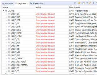
根据您的建议、我在 while 循环中添加了一个断点。
但 UART5寄存器显示启用读取。 有什么想法吗?
我得到以下结果。 还插入了我更改的3个文件。
谢谢
Kiran
//*****************************************************************************
//
// uart_echo.c - Example for reading data from and writing data to the UART in
//               an interrupt driven fashion.
//
// Copyright (c) 2013-2017 Texas Instruments Incorporated.  All rights reserved.
// Software License Agreement
//
// Texas Instruments (TI) is supplying this software for use solely and
// exclusively on TI's microcontroller products. The software is owned by
// TI and/or its suppliers, and is protected under applicable copyright
// laws. You may not combine this software with "viral" open-source
// software in order to form a larger program.
//
// THIS SOFTWARE IS PROVIDED "AS IS" AND WITH ALL FAULTS.
// NO WARRANTIES, WHETHER EXPRESS, IMPLIED OR STATUTORY, INCLUDING, BUT
// NOT LIMITED TO, IMPLIED WARRANTIES OF MERCHANTABILITY AND FITNESS FOR
// A PARTICULAR PURPOSE APPLY TO THIS SOFTWARE. TI SHALL NOT, UNDER ANY
// CIRCUMSTANCES, BE LIABLE FOR SPECIAL, INCIDENTAL, OR CONSEQUENTIAL
// DAMAGES, FOR ANY REASON WHATSOEVER.
//
// This is part of revision 2.1.4.178 of the DK-TM4C129X Firmware Package.
//
//*****************************************************************************

#include <stdint.h>
#include <stdbool.h>
#include "inc/hw_ints.h"
#include "inc/hw_memmap.h"
#include "inc/hw_types.h"
#include "driverlib/debug.h"
#include "driverlib/gpio.h"
#include "driverlib/interrupt.h"
#include "driverlib/sysctl.h"
#include "driverlib/uart.h"
#include "driverlib/rom.h"
#include "driverlib/rom_map.h"
#include "grlib/grlib.h"
#include "drivers/kentec320x240x16_ssd2119.h"
#include "drivers/frame.h"
#include "drivers/pinout.h"

//*****************************************************************************
//
//! \addtogroup example_list
//! <h1>UART Echo (uart_echo)</h1>
//!
//! This example application utilizes the UART to echo text.  The first UART
//! (connected to the FTDI virtual serial port on the evaluation board) will be
//! configured in 115,200 baud, 8-n-1 mode.  All characters received on the
//! UART are transmitted back to the UART.
//
//*****************************************************************************

//*****************************************************************************
//
// The error routine that is called if the driver library encounters an error.
//
//*****************************************************************************
#ifdef DEBUG
void
__error__(char *pcFilename, uint32_t ui32Line)
{
}
#endif

//*****************************************************************************
//
// The UART interrupt handler.
//
//*****************************************************************************
void
UARTIntHandler(void)
{
    uint32_t ui32Status;

    //
    // Get the interrrupt status.
    //
    ui32Status = ROM_UARTIntStatus(UART5_BASE, true);

    //
    // Clear the asserted interrupts.
    //
    ROM_UARTIntClear(UART5_BASE, ui32Status);

    //
    // Loop while there are characters in the receive FIFO.
    //
    while(ROM_UARTCharsAvail(UART5_BASE))
    {
        //
        // Read the next character from the UART and write it back to the UART.
        //
        ROM_UARTCharPutNonBlocking(UART5_BASE,
                                   UARTCharGetNonBlocking(UART5_BASE));
    }
}

//*****************************************************************************
//
// Send a string to the UART.
//
//*****************************************************************************
void
UARTSend(const uint8_t *pui8Buffer, uint32_t ui32Count)
{
    //
    // Loop while there are more characters to send.
    //
    while(ui32Count--)
    {
        //
        // Write the next character to the UART.
        //
        ROM_UARTCharPutNonBlocking(UART5_BASE, *pui8Buffer++);
    }
}

//*****************************************************************************
//
// This example demonstrates how to send a string of data to the UART.
//
//*****************************************************************************
int
main(void)
{
    volatile uint32_t ui32Loop;
    uint32_t ui32SysClock;
    tContext sContext;

    //
    // Run from the PLL at 120 MHz.
    //
   ui32SysClock = MAP_SysCtlClockFreqSet((SYSCTL_XTAL_25MHZ |
                                           SYSCTL_OSC_MAIN | SYSCTL_USE_PLL |
                                           SYSCTL_CFG_VCO_480), 120000000);

    //
    // Configure the device pins.
    //
    PinoutSet();

    //
    // Initialize the display driver.
    //
    Kentec320x240x16_SSD2119Init(ui32SysClock);

    //
    // Initialize the graphics context.
    //
    GrContextInit(&sContext, &g_sKentec320x240x16_SSD2119);

    //
    // Draw the application frame.
    //
    FrameDraw(&sContext, "uart-echo");

    //
    // Display UART configuration on the display.
    //
    GrStringDraw(&sContext, "Port:",       -1,  70, 70, 0);
    GrStringDraw(&sContext, "Baud:",       -1,  70, 95, 0);
    GrStringDraw(&sContext, "Data:",       -1,  70, 120, 0);
    GrStringDraw(&sContext, "Parity:",     -1,  70, 145, 0);
    GrStringDraw(&sContext, "Stop:",       -1,  70, 170, 0);
    GrStringDraw(&sContext, "Uart 5",      -1, 150, 70, 0);
    GrStringDraw(&sContext, "115,200 bps", -1, 150, 95, 0);
    GrStringDraw(&sContext, "8 Bit",       -1, 150, 120, 0);
    GrStringDraw(&sContext, "None",        -1, 150, 145, 0);
    GrStringDraw(&sContext, "1 Bit",       -1, 150, 170, 0);

    //
    // Enable the (non-GPIO) peripherals used by this example.  PinoutSet()
    // already enabled GPIO Port A.
    //
    ROM_SysCtlPeripheralEnable(SYSCTL_PERIPH_UART5);

    //
    // Enable processor interrupts.
    //
    IntMasterEnable();

    //
    // Configure the UART for 115,200, 8-N-1 operation.
    //
    ROM_UARTConfigSetExpClk(UART5_BASE, ui32SysClock, 115200,
                            (UART_CONFIG_WLEN_8 | UART_CONFIG_STOP_ONE |
                             UART_CONFIG_PAR_NONE));

    //
    // Enable the UART interrupt.
    //
    ROM_IntEnable(INT_UART5);
    ROM_UARTIntEnable(UART5_BASE, UART_INT_RX | UART_INT_RT);

    //
    // Prompt for text to be entered.
    //
    UARTSend((uint8_t *)"Enter text: ", 12);

    //
    // Loop forever echoing data through the UART.
    //
    while(1)
    {
        UARTSend((uint8_t *)"Enter text: ", 12);
        for(ui32Loop = 0; ui32Loop < 1340000; ui32Loop++) // 1 second ON
        {
        }
    }
}
//*****************************************************************************
//
// pinout.c - Function to configure the device pins on the DK-TM4C129X.
//
// Copyright (c) 2013-2017 Texas Instruments Incorporated.  All rights reserved.
// Software License Agreement
//
// Texas Instruments (TI) is supplying this software for use solely and
// exclusively on TI's microcontroller products. The software is owned by
// TI and/or its suppliers, and is protected under applicable copyright
// laws. You may not combine this software with "viral" open-source
// software in order to form a larger program.
//
// THIS SOFTWARE IS PROVIDED "AS IS" AND WITH ALL FAULTS.
// NO WARRANTIES, WHETHER EXPRESS, IMPLIED OR STATUTORY, INCLUDING, BUT
// NOT LIMITED TO, IMPLIED WARRANTIES OF MERCHANTABILITY AND FITNESS FOR
// A PARTICULAR PURPOSE APPLY TO THIS SOFTWARE. TI SHALL NOT, UNDER ANY
// CIRCUMSTANCES, BE LIABLE FOR SPECIAL, INCIDENTAL, OR CONSEQUENTIAL
// DAMAGES, FOR ANY REASON WHATSOEVER.
//
// This is part of revision 2.1.4.178 of the DK-TM4C129X Firmware Package.
//
//*****************************************************************************

#include <stdbool.h>
#include <stdint.h>
#include "inc/hw_gpio.h"
#include "inc/hw_memmap.h"
#include "inc/hw_types.h"
#include "driverlib/gpio.h"
#include "driverlib/pin_map.h"
#include "driverlib/rom.h"
#include "driverlib/sysctl.h"
#include "drivers/pinout.h"

//*****************************************************************************
//
//! \addtogroup pinout_api
//! @{
//
//*****************************************************************************

//*****************************************************************************
//
//! Configures the device pins for the standard usages on the DK-TM4C129X.
//!
//! This function enables the GPIO modules and configures the device pins for
//! the default, standard usages on the DK-TM4C129X.  Applications that require
//! alternate configurations of the device pins can either not call this
//! function and take full responsibility for configuring all the device pins,
//! or can reconfigure the required device pins after calling this function.
//!
//! \return None.
//
//*****************************************************************************
void
PinoutSet(void)
{
    //
    // Enable all the GPIO peripherals.
    //
    ROM_SysCtlPeripheralEnable(SYSCTL_PERIPH_GPIOA);
    ROM_SysCtlPeripheralEnable(SYSCTL_PERIPH_GPIOB);
    ROM_SysCtlPeripheralEnable(SYSCTL_PERIPH_GPIOC);
    ROM_SysCtlPeripheralEnable(SYSCTL_PERIPH_GPIOD);
    ROM_SysCtlPeripheralEnable(SYSCTL_PERIPH_GPIOE);
    ROM_SysCtlPeripheralEnable(SYSCTL_PERIPH_GPIOF);
    ROM_SysCtlPeripheralEnable(SYSCTL_PERIPH_GPIOG);
    ROM_SysCtlPeripheralEnable(SYSCTL_PERIPH_GPIOH);
    ROM_SysCtlPeripheralEnable(SYSCTL_PERIPH_GPIOJ);
    ROM_SysCtlPeripheralEnable(SYSCTL_PERIPH_GPIOK);
    ROM_SysCtlPeripheralEnable(SYSCTL_PERIPH_GPIOL);
    ROM_SysCtlPeripheralEnable(SYSCTL_PERIPH_GPIOM);
    ROM_SysCtlPeripheralEnable(SYSCTL_PERIPH_GPION);
    ROM_SysCtlPeripheralEnable(SYSCTL_PERIPH_GPIOP);
    ROM_SysCtlPeripheralEnable(SYSCTL_PERIPH_GPIOQ);
    ROM_SysCtlPeripheralEnable(SYSCTL_PERIPH_GPIOR);
    ROM_SysCtlPeripheralEnable(SYSCTL_PERIPH_GPIOS);
    ROM_SysCtlPeripheralEnable(SYSCTL_PERIPH_GPIOT);

    //
    // PA0-1 are used for UART0.
    //
 //   ROM_GPIOPinConfigure(GPIO_PA0_U0RX);
 //   ROM_GPIOPinConfigure(GPIO_PA1_U0TX);
 //   ROM_GPIOPinTypeUART(GPIO_PORTA_BASE, GPIO_PIN_0 | GPIO_PIN_1);

    //
    // PB0-1 are used for UART1.
    //
//    ROM_GPIOPinConfigure(GPIO_PB0_U1RX);
//    ROM_GPIOPinConfigure(GPIO_PB1_U1TX);
//    ROM_GPIOPinTypeUART(GPIO_PORTB_BASE, GPIO_PIN_0 | GPIO_PIN_1);
    //
    // PC6/PH7 are used for UART5.
    //
    ROM_GPIOPinConfigure(GPIO_PC6_U5RX);
    ROM_GPIOPinConfigure(GPIO_PH7_U5TX);
    ROM_GPIOPinTypeUART(GPIO_PORTC_BASE, GPIO_PIN_6);
    ROM_GPIOPinTypeUART(GPIO_PORTH_BASE, GPIO_PIN_7);

    //
    // PA2-5 are used for SSI0 to the second booster pack.
    //
    ROM_GPIOPinConfigure(GPIO_PA2_SSI0CLK);
    ROM_GPIOPinConfigure(GPIO_PA3_SSI0FSS);
    ROM_GPIOPinConfigure(GPIO_PA4_SSI0XDAT0);
    ROM_GPIOPinConfigure(GPIO_PA5_SSI0XDAT1);

    //
    // PB0-1/PD6-7/PL6-7 are used for USB.
    //
    HWREG(GPIO_PORTD_BASE + GPIO_O_LOCK) = GPIO_LOCK_KEY;
    HWREG(GPIO_PORTD_BASE + GPIO_O_CR) = 0xff;
    ROM_GPIOPinConfigure(GPIO_PD6_USB0EPEN);
    ROM_GPIOPinConfigure(GPIO_PD7_USB0PFLT);
    ROM_GPIOPinTypeUSBAnalog(GPIO_PORTB_BASE, GPIO_PIN_0 | GPIO_PIN_1);
    ROM_GPIOPinTypeUSBDigital(GPIO_PORTD_BASE, GPIO_PIN_6 | GPIO_PIN_7);
    ROM_GPIOPinTypeUSBAnalog(GPIO_PORTL_BASE, GPIO_PIN_6 | GPIO_PIN_7);

    //
    // PB2/PD4 are used for the speaker output.
    //
    ROM_GPIOPinConfigure(GPIO_PB2_T5CCP0);
    ROM_GPIOPinTypeTimer(GPIO_PORTB_BASE, GPIO_PIN_2);
    ROM_GPIOPinTypeGPIOOutput(GPIO_PORTD_BASE, GPIO_PIN_4);
    ROM_GPIOPinWrite(GPIO_PORTD_BASE, GPIO_PIN_4, 0);

    //
    // PB6-7 are used for I2C to the TMP100 and the EM connector.
    //
    ROM_GPIOPinConfigure(GPIO_PB6_I2C6SCL);
    ROM_GPIOPinConfigure(GPIO_PB7_I2C6SDA);
    ROM_GPIOPinTypeI2CSCL(GPIO_PORTB_BASE, GPIO_PIN_6);
    ROM_GPIOPinTypeI2C(GPIO_PORTB_BASE, GPIO_PIN_7);

    //
    // PE5/PN3/PP1 are used for the push buttons.
    //
    ROM_GPIOPinTypeGPIOInput(GPIO_PORTE_BASE, GPIO_PIN_5);
    ROM_GPIOPinTypeGPIOInput(GPIO_PORTN_BASE, GPIO_PIN_3);
    ROM_GPIOPinTypeGPIOInput(GPIO_PORTP_BASE, GPIO_PIN_1);

    //
    // PE7/PP7/PT2-3 are used for the touch screen.
    //
    HWREG(GPIO_PORTE_BASE + GPIO_O_LOCK) = GPIO_LOCK_KEY;
    HWREG(GPIO_PORTE_BASE + GPIO_O_CR) = 0xff;
    ROM_GPIOPinTypeGPIOInput(GPIO_PORTE_BASE, GPIO_PIN_7);
    ROM_GPIOPinTypeGPIOInput(GPIO_PORTP_BASE, GPIO_PIN_7);
    ROM_GPIOPinTypeGPIOInput(GPIO_PORTT_BASE, GPIO_PIN_2 | GPIO_PIN_3);
    ROM_GPIOPinTypeGPIOOutput(GPIO_PORTE_BASE, GPIO_PIN_7);
    ROM_GPIOPinWrite(GPIO_PORTE_BASE, GPIO_PIN_7, 0);
    ROM_GPIOPinTypeGPIOOutput(GPIO_PORTP_BASE, GPIO_PIN_7);
    ROM_GPIOPinWrite(GPIO_PORTP_BASE, GPIO_PIN_7, 0);
    ROM_GPIOPinTypeGPIOOutput(GPIO_PORTT_BASE, GPIO_PIN_2 | GPIO_PIN_3);
    ROM_GPIOPinWrite(GPIO_PORTT_BASE, GPIO_PIN_2 | GPIO_PIN_3, 0);

    //
    // PF0/PF4-5/PH4/PQ0-2 are used for the SPI flash (on-board and SD card).
    // PH4 selects the SD card and PQ1 selects the on-board SPI flash.
    //
    ROM_GPIOPinConfigure(GPIO_PF0_SSI3XDAT1);
    ROM_GPIOPinConfigure(GPIO_PF4_SSI3XDAT2);
    ROM_GPIOPinConfigure(GPIO_PF5_SSI3XDAT3);
    ROM_GPIOPinConfigure(GPIO_PQ0_SSI3CLK);
    ROM_GPIOPinConfigure(GPIO_PQ2_SSI3XDAT0);
    ROM_GPIOPinTypeSSI(GPIO_PORTF_BASE, GPIO_PIN_0 | GPIO_PIN_4 | GPIO_PIN_5);
    ROM_GPIOPinTypeGPIOOutput(GPIO_PORTH_BASE, GPIO_PIN_4);
    ROM_GPIOPinWrite(GPIO_PORTH_BASE, GPIO_PIN_4, GPIO_PIN_4);
    ROM_GPIOPinTypeSSI(GPIO_PORTQ_BASE, GPIO_PIN_0 | GPIO_PIN_2);
    ROM_GPIOPinTypeGPIOOutput(GPIO_PORTQ_BASE, GPIO_PIN_1);
    ROM_GPIOPinWrite(GPIO_PORTQ_BASE, GPIO_PIN_1, GPIO_PIN_1);

    //
    // PF1/PK4/PK6 are used for Ethernet LEDs.
    //
    ROM_GPIOPinConfigure(GPIO_PF1_EN0LED2);
    ROM_GPIOPinConfigure(GPIO_PK4_EN0LED0);
    ROM_GPIOPinConfigure(GPIO_PK6_EN0LED1);
    GPIOPinTypeEthernetLED(GPIO_PORTF_BASE, GPIO_PIN_1);
    GPIOPinTypeEthernetLED(GPIO_PORTK_BASE, GPIO_PIN_4);
    GPIOPinTypeEthernetLED(GPIO_PORTK_BASE, GPIO_PIN_6);

    //
    // PF6-7/PJ6/PS4-5/PR0-7 are used for the LCD.
    //
    ROM_GPIOPinConfigure(GPIO_PF7_LCDDATA02);
    ROM_GPIOPinConfigure(GPIO_PJ6_LCDAC);
    ROM_GPIOPinConfigure(GPIO_PR0_LCDCP);
    ROM_GPIOPinConfigure(GPIO_PR1_LCDFP);
    ROM_GPIOPinConfigure(GPIO_PR2_LCDLP);
    ROM_GPIOPinConfigure(GPIO_PR3_LCDDATA03);
    ROM_GPIOPinConfigure(GPIO_PR4_LCDDATA00);
    ROM_GPIOPinConfigure(GPIO_PR5_LCDDATA01);
    ROM_GPIOPinConfigure(GPIO_PR6_LCDDATA04);
    ROM_GPIOPinConfigure(GPIO_PR7_LCDDATA05);
    ROM_GPIOPinConfigure(GPIO_PS4_LCDDATA06);
    ROM_GPIOPinConfigure(GPIO_PS5_LCDDATA07);
    ROM_GPIOPinTypeGPIOOutput(GPIO_PORTF_BASE, GPIO_PIN_6);
    ROM_GPIOPinWrite(GPIO_PORTF_BASE, GPIO_PIN_6, GPIO_PIN_6);
    GPIOPinTypeLCD(GPIO_PORTF_BASE, GPIO_PIN_7);
    GPIOPinTypeLCD(GPIO_PORTJ_BASE, GPIO_PIN_6);
    GPIOPinTypeLCD(GPIO_PORTR_BASE,
                       (GPIO_PIN_0 | GPIO_PIN_1 | GPIO_PIN_2 | GPIO_PIN_3 |
                        GPIO_PIN_4 | GPIO_PIN_5 | GPIO_PIN_6 | GPIO_PIN_7));
    GPIOPinTypeLCD(GPIO_PORTS_BASE, GPIO_PIN_4 | GPIO_PIN_5);

    //
    // PQ7 is used for the user LED.
    //
    ROM_GPIOPinTypeGPIOOutput(GPIO_PORTQ_BASE, GPIO_PIN_7);
    ROM_GPIOPinWrite(GPIO_PORTQ_BASE, GPIO_PIN_7, 0);
}

//*****************************************************************************
//
//! Configures the USB pins for ULPI connection to an external USB PHY.
//!
//! This function configures the USB ULPI pins to connect the DK-TM4C129X board
//! to an external USB PHY in ULPI mode.  This allows the external PHY to act
//! as an external high-speed phy for the DK-TM4C129X.  This function must be
//! called after the call to PinoutSet() to properly configure the pins.
//!
//! \return None.
//
//*****************************************************************************
#ifdef USE_ULPI
void
USBULPIPinoutSet(void)
{
    //
    // Enable all the peripherals that are used by the ULPI interface.
    //
    ROM_SysCtlPeripheralEnable(SYSCTL_PERIPH_GPIOB);
    ROM_SysCtlPeripheralEnable(SYSCTL_PERIPH_GPIOL);
    ROM_SysCtlPeripheralEnable(SYSCTL_PERIPH_GPIOM);
    ROM_SysCtlPeripheralEnable(SYSCTL_PERIPH_GPIOP);

    //
    // ULPI Port B pins.
    //
    ROM_GPIOPinConfigure(GPIO_PB2_USB0STP);
    ROM_GPIOPinConfigure(GPIO_PB3_USB0CLK);
    ROM_GPIOPinTypeUSBDigital(GPIO_PORTB_BASE, GPIO_PIN_2 | GPIO_PIN_3);
    GPIOPadConfigSet(GPIO_PORTB_BASE, GPIO_PIN_2 | GPIO_PIN_3,
                     GPIO_STRENGTH_12MA, GPIO_PIN_TYPE_STD);

    //
    // ULPI Port P pins.
    //
    ROM_GPIOPinConfigure(GPIO_PP2_USB0NXT);
    ROM_GPIOPinConfigure(GPIO_PP3_USB0DIR);
    ROM_GPIOPinConfigure(GPIO_PP4_USB0D7);
    ROM_GPIOPinConfigure(GPIO_PP5_USB0D6);
    ROM_GPIOPinTypeUSBDigital(GPIO_PORTP_BASE, GPIO_PIN_2 | GPIO_PIN_3 |
                                               GPIO_PIN_4 | GPIO_PIN_5);
    GPIOPadConfigSet(GPIO_PORTP_BASE,
                     GPIO_PIN_2 | GPIO_PIN_3 | GPIO_PIN_4 | GPIO_PIN_5,
                     GPIO_STRENGTH_12MA, GPIO_PIN_TYPE_STD);

    //
    // ULPI Port L pins.
    //
    ROM_GPIOPinConfigure(GPIO_PL5_USB0D5);
    ROM_GPIOPinConfigure(GPIO_PL4_USB0D4);
    ROM_GPIOPinConfigure(GPIO_PL3_USB0D3);
    ROM_GPIOPinConfigure(GPIO_PL2_USB0D2);
    ROM_GPIOPinConfigure(GPIO_PL1_USB0D1);
    ROM_GPIOPinConfigure(GPIO_PL0_USB0D0);
    ROM_GPIOPinTypeUSBDigital(GPIO_PORTL_BASE, GPIO_PIN_0 | GPIO_PIN_1 |
                                               GPIO_PIN_2 | GPIO_PIN_3 |
                                               GPIO_PIN_4 | GPIO_PIN_5);
    GPIOPadConfigSet(GPIO_PORTL_BASE,
                     GPIO_PIN_0 | GPIO_PIN_1 | GPIO_PIN_2 | GPIO_PIN_3 |
                     GPIO_PIN_4 | GPIO_PIN_5,
                     GPIO_STRENGTH_12MA, GPIO_PIN_TYPE_STD);
    //
    // ULPI Port M pins used to control the external USB oscillator and the
    // external USB phy on the DK-TM4C129X-DPHY board.
    //
    // PM1 - Enables the USB oscillator on the DK-TM4C129X-DPHY board.
    // PM3 - Enables the USB phy on the DK-TM4C129X-DPHY board.
    //
    ROM_GPIOPinTypeGPIOOutput(GPIO_PORTM_BASE, GPIO_PIN_1 | GPIO_PIN_3);
    ROM_GPIOPinWrite(GPIO_PORTM_BASE, GPIO_PIN_1 | GPIO_PIN_3, GPIO_PIN_1 |
                                                               GPIO_PIN_3);
}
#endif

//*****************************************************************************
//
// Close the Doxygen group.
//! @}
//
//*****************************************************************************
//*****************************************************************************
//
// startup_ccs.c - Startup code for use with TI's Code Composer Studio.
//
// Copyright (c) 2013-2017 Texas Instruments Incorporated.  All rights reserved.
// Software License Agreement
//
// Texas Instruments (TI) is supplying this software for use solely and
// exclusively on TI's microcontroller products. The software is owned by
// TI and/or its suppliers, and is protected under applicable copyright
// laws. You may not combine this software with "viral" open-source
// software in order to form a larger program.
//
// THIS SOFTWARE IS PROVIDED "AS IS" AND WITH ALL FAULTS.
// NO WARRANTIES, WHETHER EXPRESS, IMPLIED OR STATUTORY, INCLUDING, BUT
// NOT LIMITED TO, IMPLIED WARRANTIES OF MERCHANTABILITY AND FITNESS FOR
// A PARTICULAR PURPOSE APPLY TO THIS SOFTWARE. TI SHALL NOT, UNDER ANY
// CIRCUMSTANCES, BE LIABLE FOR SPECIAL, INCIDENTAL, OR CONSEQUENTIAL
// DAMAGES, FOR ANY REASON WHATSOEVER.
//
// This is part of revision 2.1.4.178 of the DK-TM4C129X Firmware Package.
//
//*****************************************************************************

#include <stdint.h>
#include "inc/hw_nvic.h"
#include "inc/hw_types.h"

//*****************************************************************************
//
// Forward declaration of the default fault handlers.
//
//*****************************************************************************
void ResetISR(void);
static void NmiSR(void);
static void FaultISR(void);
static void IntDefaultHandler(void);

//*****************************************************************************
//
// External declaration for the reset handler that is to be called when the
// processor is started
//
//*****************************************************************************
extern void _c_int00(void);

//*****************************************************************************
//
// Linker variable that marks the top of the stack.
//
//*****************************************************************************
extern uint32_t __STACK_TOP;

//*****************************************************************************
//
// External declaration for the interrupt handler used by the application.
//
//*****************************************************************************
extern void UARTIntHandler(void);

//*****************************************************************************
//
// The vector table.  Note that the proper constructs must be placed on this to
// ensure that it ends up at physical address 0x0000.0000 or at the start of
// the program if located at a start address other than 0.
//
//*****************************************************************************
#pragma DATA_SECTION(g_pfnVectors, ".intvecs")
void (* const g_pfnVectors[])(void) =
{
    (void (*)(void))((uint32_t)&__STACK_TOP),
                                            // The initial stack pointer
    ResetISR,                               // The reset handler
    NmiSR,                                  // The NMI handler
    FaultISR,                               // The hard fault handler
    IntDefaultHandler,                      // The MPU fault handler
    IntDefaultHandler,                      // The bus fault handler
    IntDefaultHandler,                      // The usage fault handler
    0,                                      // Reserved
    0,                                      // Reserved
    0,                                      // Reserved
    0,                                      // Reserved
    IntDefaultHandler,                      // SVCall handler
    IntDefaultHandler,                      // Debug monitor handler
    0,                                      // Reserved
    IntDefaultHandler,                      // The PendSV handler
    IntDefaultHandler,                      // The SysTick handler
    IntDefaultHandler,                      // GPIO Port A
    IntDefaultHandler,                      // GPIO Port B
    IntDefaultHandler,                      // GPIO Port C
    IntDefaultHandler,                      // GPIO Port D
    IntDefaultHandler,                      // GPIO Port E
    IntDefaultHandler,                         // UART0 Rx and Tx
    IntDefaultHandler,                      // UART1 Rx and Tx
    IntDefaultHandler,                      // SSI0 Rx and Tx
    IntDefaultHandler,                      // I2C0 Master and Slave
    IntDefaultHandler,                      // PWM Fault
    IntDefaultHandler,                      // PWM Generator 0
    IntDefaultHandler,                      // PWM Generator 1
    IntDefaultHandler,                      // PWM Generator 2
    IntDefaultHandler,                      // Quadrature Encoder 0
    IntDefaultHandler,                      // ADC Sequence 0
    IntDefaultHandler,                      // ADC Sequence 1
    IntDefaultHandler,                      // ADC Sequence 2
    IntDefaultHandler,                      // ADC Sequence 3
    IntDefaultHandler,                      // Watchdog timer
    IntDefaultHandler,                      // Timer 0 subtimer A
    IntDefaultHandler,                      // Timer 0 subtimer B
    IntDefaultHandler,                      // Timer 1 subtimer A
    IntDefaultHandler,                      // Timer 1 subtimer B
    IntDefaultHandler,                      // Timer 2 subtimer A
    IntDefaultHandler,                      // Timer 2 subtimer B
    IntDefaultHandler,                      // Analog Comparator 0
    IntDefaultHandler,                      // Analog Comparator 1
    IntDefaultHandler,                      // Analog Comparator 2
    IntDefaultHandler,                      // System Control (PLL, OSC, BO)
    IntDefaultHandler,                      // FLASH Control
    IntDefaultHandler,                      // GPIO Port F
    IntDefaultHandler,                      // GPIO Port G
    IntDefaultHandler,                      // GPIO Port H
    IntDefaultHandler,                      // UART2 Rx and Tx
    IntDefaultHandler,                      // SSI1 Rx and Tx
    IntDefaultHandler,                      // Timer 3 subtimer A
    IntDefaultHandler,                      // Timer 3 subtimer B
    IntDefaultHandler,                      // I2C1 Master and Slave
    IntDefaultHandler,                      // CAN0
    IntDefaultHandler,                      // CAN1
    IntDefaultHandler,                      // Ethernet
    IntDefaultHandler,                      // Hibernate
    IntDefaultHandler,                      // USB0
    IntDefaultHandler,                      // PWM Generator 3
    IntDefaultHandler,                      // uDMA Software Transfer
    IntDefaultHandler,                      // uDMA Error
    IntDefaultHandler,                      // ADC1 Sequence 0
    IntDefaultHandler,                      // ADC1 Sequence 1
    IntDefaultHandler,                      // ADC1 Sequence 2
    IntDefaultHandler,                      // ADC1 Sequence 3
    IntDefaultHandler,                      // External Bus Interface 0
    IntDefaultHandler,                      // GPIO Port J
    IntDefaultHandler,                      // GPIO Port K
    IntDefaultHandler,                      // GPIO Port L
    IntDefaultHandler,                      // SSI2 Rx and Tx
    IntDefaultHandler,                      // SSI3 Rx and Tx
    IntDefaultHandler,                      // UART3 Rx and Tx
    IntDefaultHandler,                      // UART4 Rx and Tx
    UARTIntHandler,                      // UART5 Rx and Tx
    IntDefaultHandler,                      // UART6 Rx and Tx
    IntDefaultHandler,                      // UART7 Rx and Tx
    IntDefaultHandler,                      // I2C2 Master and Slave
    IntDefaultHandler,                      // I2C3 Master and Slave
    IntDefaultHandler,                      // Timer 4 subtimer A
    IntDefaultHandler,                      // Timer 4 subtimer B
    IntDefaultHandler,                      // Timer 5 subtimer A
    IntDefaultHandler,                      // Timer 5 subtimer B
    IntDefaultHandler,                      // FPU
    0,                                      // Reserved
    0,                                      // Reserved
    IntDefaultHandler,                      // I2C4 Master and Slave
    IntDefaultHandler,                      // I2C5 Master and Slave
    IntDefaultHandler,                      // GPIO Port M
    IntDefaultHandler,                      // GPIO Port N
    0,                                      // Reserved
    IntDefaultHandler,                      // Tamper
    IntDefaultHandler,                      // GPIO Port P (Summary or P0)
    IntDefaultHandler,                      // GPIO Port P1
    IntDefaultHandler,                      // GPIO Port P2
    IntDefaultHandler,                      // GPIO Port P3
    IntDefaultHandler,                      // GPIO Port P4
    IntDefaultHandler,                      // GPIO Port P5
    IntDefaultHandler,                      // GPIO Port P6
    IntDefaultHandler,                      // GPIO Port P7
    IntDefaultHandler,                      // GPIO Port Q (Summary or Q0)
    IntDefaultHandler,                      // GPIO Port Q1
    IntDefaultHandler,                      // GPIO Port Q2
    IntDefaultHandler,                      // GPIO Port Q3
    IntDefaultHandler,                      // GPIO Port Q4
    IntDefaultHandler,                      // GPIO Port Q5
    IntDefaultHandler,                      // GPIO Port Q6
    IntDefaultHandler,                      // GPIO Port Q7
    IntDefaultHandler,                      // GPIO Port R
    IntDefaultHandler,                      // GPIO Port S
    IntDefaultHandler,                      // SHA/MD5 0
    IntDefaultHandler,                      // AES 0
    IntDefaultHandler,                      // DES3DES 0
    IntDefaultHandler,                      // LCD Controller 0
    IntDefaultHandler,                      // Timer 6 subtimer A
    IntDefaultHandler,                      // Timer 6 subtimer B
    IntDefaultHandler,                      // Timer 7 subtimer A
    IntDefaultHandler,                      // Timer 7 subtimer B
    IntDefaultHandler,                      // I2C6 Master and Slave
    IntDefaultHandler,                      // I2C7 Master and Slave
    IntDefaultHandler,                      // HIM Scan Matrix Keyboard 0
    IntDefaultHandler,                      // One Wire 0
    IntDefaultHandler,                      // HIM PS/2 0
    IntDefaultHandler,                      // HIM LED Sequencer 0
    IntDefaultHandler,                      // HIM Consumer IR 0
    IntDefaultHandler,                      // I2C8 Master and Slave
    IntDefaultHandler,                      // I2C9 Master and Slave
    IntDefaultHandler                       // GPIO Port T
};

//*****************************************************************************
//
// This is the code that gets called when the processor first starts execution
// following a reset event.  Only the absolutely necessary set is performed,
// after which the application supplied entry() routine is called.  Any fancy
// actions (such as making decisions based on the reset cause register, and
// resetting the bits in that register) are left solely in the hands of the
// application.
//
//*****************************************************************************
void
ResetISR(void)
{
    //
    // Jump to the CCS C initialization routine.  This will enable the
    // floating-point unit as well, so that does not need to be done here.
    //
    __asm("    .global _c_int00\n"
          "    b.w     _c_int00");
}

//*****************************************************************************
//
// This is the code that gets called when the processor receives a NMI.  This
// simply enters an infinite loop, preserving the system state for examination
// by a debugger.
//
//*****************************************************************************
static void
NmiSR(void)
{
    //
    // Enter an infinite loop.
    //
    while(1)
    {
    }
}

//*****************************************************************************
//
// This is the code that gets called when the processor receives a fault
// interrupt.  This simply enters an infinite loop, preserving the system state
// for examination by a debugger.
//
//*****************************************************************************
static void
FaultISR(void)
{
    //
    // Enter an infinite loop.
    //
    while(1)
    {
    }
}

//*****************************************************************************
//
// This is the code that gets called when the processor receives an unexpected
// interrupt.  This simply enters an infinite loop, preserving the system state
// for examination by a debugger.
//
//*****************************************************************************
static void
IntDefaultHandler(void)
{
    //
    // Go into an infinite loop.
    //
    while(1)
    {
    }
}

