This thread has been locked.
If you have a related question, please click the "Ask a related question" button in the top right corner. The newly created question will be automatically linked to this question.
大家好!
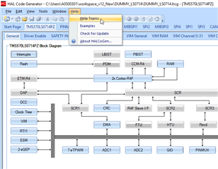
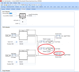
我想在 TMS570LS0714APZ 上的多路复用引脚12上生成 PWM 信号(~60kHz)。 该引脚的默认功能是 GIO。
我在一些文章中介绍了使用 NHET 模块生成可变占空比 PWM、但我发现很难使用 HET 编译器生成该占空比(如果我错、请更正我)。
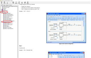
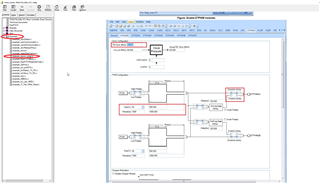
我认为的另一个解决方法是引脚上的 ePWM 功能。 如何才能做到这一点?
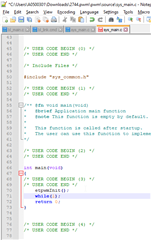
为此需要执行哪些步骤?
请询问您是否需要任何其他详细信息。
尊敬的 Salah 先生:
我推荐一些文章使用 NHET 模块生成可变占空比 PWM,但很难使用 HET 编译器来生成该占空比(如果我错,请更正我)。
对于从 NHET 生成 PWM 的简单方法不需要 HET 编译器、您可以轻松地从 HALCoGen 自身生成它。
如果您转到 HALCoGen 中的"帮助主题"部分、
在这里、您可以找到直接从 HALCoGen 生成 HET PWM 的分步过程和代码、而无需使用 HET 编译器。
Unknown 说:另一件事我认为是引脚上的 EPWM 功能。 如何实现这一点?
是的、您也可以使用 ePWM。
在"帮助主题"中、还有一个名为"etpwm_ecap"的示例
该示例基于 ETPWM 和 ECAP、因此在此处您可以忽略 ECAP 相关的配置和代码、并且您可以仅使用 ETPWM 相关配置和代码来生成 ETPWM。
您还可以参考以下两个我创建的 ETPWM 示例:
e2e.ti.com/.../ETPWM_5F00_Example_5F00_RM46.zip
e2e.ti.com/.../ETPWM_5F00_TEST_5F00_LC43.zip
--
谢谢。此致、
Jagadish。
非常感谢您的答复。
我在参考帮助主题链接时有一些见解、但有点困惑。
我的要求是、我必须将 PWM 信号应用于连接到 TMS570LS0914的 EPWM4B (引脚25)上的 LED。
出于测试目的、我们可以生成1秒周期、占空比为50%。
以下是我使用 Halcogen 生成的代码(经过一些修改)。 我将观察到 TBCTR 在递增、直到 TBPRD 并且它正在复位。 它不考虑 CMPB 寄存器中的值。 (我在尝试测试时、在 TBPRD 和 CMPB 中加载的值可能错误)
void etpwmInit(void) { /** - Sets high speed time-base clock prescale bits */ etpwmREG4->TBCTL = (uint16)0U << 7U; /** - Sets time-base clock prescale bits */ etpwmREG4->TBCTL |= (uint16)((uint16)0U << 10U); /** - Sets time period or frequency for ETPWM block both PWMA and PWMB*/ etpwmREG4->TBPRD = 5000; /** - Setup the duty cycle for PWMA */ etpwmREG4->CMPA = 2000U; /** - Setup the duty cycle for PWMB */ etpwmREG4->CMPB = 1000U; /** - Force EPWMxA output high when counter reaches zero and low when counter reaches Compare A value */ etpwmREG4->AQCTLA = ((uint16)((uint16)ActionQual_Set << 0U) | (uint16)((uint16)ActionQual_Clear << 4U)); /** - Force EPWMxB output high when counter reaches zero and low when counter reaches Compare B value */ etpwmREG4->AQCTLB = ((uint16)((uint16)ActionQual_Set << 0U) | (uint16)((uint16)ActionQual_Clear << 8U)); /** - Mode setting for Dead Band Module * -Select the input mode for Dead Band Module * -Select the output mode for Dead Band Module * -Select Polarity of the output PWMs */ etpwmREG4->DBCTL = (uint16)((uint16)0U << 5U) /* Source for Falling edge delay(0-PWMA, 1-PWMB) */ | (uint16)((uint16)0U << 4U) /* Source for Rising edge delay(0-PWMA, 1-PWMB) */ | (uint16)((uint16)0U << 3U) /* Enable/Disable EPWMxB invert */ | (uint16)((uint16)0U << 2U) /* Enable/Disable EPWMxA invert */ | (uint16)((uint16)0U << 1U) /* Enable/Disable Rising Edge Delay */ | (uint16)((uint16)0U << 0U); /* Enable/Disable Falling Edge Delay */ /** - Set the rising edge delay */ etpwmREG4->DBRED = 1U; /** - Set the falling edge delay */ etpwmREG4->DBFED = 1U; /** - Enable the chopper module for ETPWMx * -Sets the One shot pulse width in a chopper modulated wave * -Sets the dutycycle for the subsequent pulse train * -Sets the period for the subsequent pulse train */ etpwmREG4->PCCTL = (uint16)((uint16)0U << 0U) /* Enable/Disable chopper module */ | (uint16)((uint16)0U << 1U) /* One-shot Pulse Width */ | (uint16)((uint16)3U << 8U) /* Chopping Clock Duty Cycle */ | (uint16)((uint16)0U << 5U); /* Chopping Clock Frequency */ /** - Set trip source enable */ etpwmREG4->TZSEL = 0x0000U /** - Enable/Disable TZ1 as a one-shot trip source */ | 0x0000U /** - Enable/Disable TZ2 as a one-shot trip source */ | 0x0000U /** - Enable/Disable TZ3 as a one-shot trip source */ | 0x0000U /** - Enable/Disable TZ4 as a one-shot trip source */ | 0x0000U /** - Enable/Disable TZ5 as a one-shot trip source */ | 0x0000U /** - Enable/Disable TZ6 as a one-shot trip source */ | 0x0000U /** - Enable/Disable TZ1 as a CBC trip source */ | 0x0000U /** - Enable/Disable TZ2 as a CBC trip source */ | 0x0000U /** - Enable/Disable TZ3 as a CBC trip source */ | 0x0000U /** - Enable/Disable TZ4 as a CBC trip source */ | 0x0000U /** - Enable/Disable TZ5 as a CBC trip source */ | 0x0000U; /** - Enable/Disable TZ6 as a CBC trip source */ /** - Set interrupt enable */ etpwmREG4->TZEINT = 0x0000U /** - Enable/Disable Digital Comparator Output A Event 1 */ | 0x0000U /** - Enable/Disable Digital Comparator Output A Event 2 */ | 0x0000U /** - Enable/Disable Digital Comparator Output A Event 1 */ | 0x0000U /** - Enable/Disable Digital Comparator Output A Event 2 */ | 0x0000U /** - Enable/Disable one-shot interrupt generation */ | 0x0000U; /** - Enable/Disable cycle-by-cycle interrupt generation */ /** - Sets up the event for interrupt */ etpwmREG4->ETSEL = (uint16)NO_EVENT; if ((etpwmREG4->ETSEL & 0x0007U) != 0U) { etpwmREG4->ETSEL |= 0x0008U; } /** - Setup the frequency of the interrupt generation */ etpwmREG4->ETPS = 1U; /** - Sets up the ADC SOC interrupt */ etpwmREG4->ETSEL |= (uint16)(0x0000U) | (uint16)(0x0000U) | (uint16)((uint16)DCAEVT1 << 8U) | (uint16)((uint16)DCBEVT1 << 12U); /** - Sets up the ADC SOC period */ etpwmREG4->ETPS |= ((uint16)((uint16)1U << 8U) | (uint16)((uint16)1U << 12U)); etpwmStartTBCLK(); } void etpwmStartTBCLK(void) { /* Enable Pin Muxing */ kickerReg->KICKER0 = 0x83E70B13U; kickerReg->KICKER1 = 0x95A4F1E0U; pinMuxReg->PINMMR[37] = (pinMuxReg->PINMMR[37] & PINMUX_ETPWM_TBCLK_SYNC_MASK) | (PINMUX_ETPWM_TBCLK_SYNC_ON); pinMuxReg->PINMMR[33] |= 0x02; /* Disable Pin Muxing */ kickerReg->KICKER0 = 0x00000000U; kickerReg->KICKER1 = 0x00000000U; } void main() { etpwmInit(); }
我在这里做错了什么? 您可以提供帮助吗?
您能否压缩并共享整个项目?
如果您不知道如何附加完整项目、请参阅以下主题:
(+) TMS570LC4357:TMS570LC43X -基于 Arm 的微控制器论坛-基于 Arm 的微控制器- TI E2E 支持论坛
Jagadish、您好!
我已经连接了我的 halcogen 项目。
当我将其纳入我的实际项目(无法披露)时、我修改了其中的一些部分(etpwm.c)。
例如,要启动 TBCLK, 不会调用 etpwmStartTBCLK()。 所以我在 etpwmInit ()里面调用了它。
基本上、我需要设置/读取最少的寄存器才能满足我的要求。 哈科根让我很困惑。
非常感谢、如果您能在我的代码(张贴在上面)中特别指出问题。
尊敬的 Salah 先生:
我有两件事怀疑!
1.我看不到代码中的 while (1)、你应该给 while (1)、因为你不应该从主函数终止。
2.为什么要为 ETPWM4_A 中的 ETPWM4_B 提供100%下降沿延迟。
而不仅仅是使 ETPWM4B 独立于 ETPWM4A、如下所示:
进行此更改并重新生成代码并进行测试。
--
谢谢。此致、
Jagadish。
很抱歉。
我在复制时错过了 while 循环。
我在使 ETPWM4B 独立于 ETPWM4A 后再生。
但观察结果仍然相同。
我希望我 在 etpwminit()后调用 etpwmStartTBCLK(),而 etpwminit()在 Halcogen 代码中没有完成。 对吧?
我希望我 在 etpwmStartTBCLK()后调用 etpwminit(),而 etpwminit()在 Halcogen 代码中没有这样做。 对吗?
是的、您是对的。 您应该称其为。
那么问题可能是什么呢?
如果 TBCTR 值变为等于 CMPB、那么我们应该获得一个中断(比较中断)、对吧?
如何实现它? 有什么回调函数需要处理这个问题吗?
尊敬的 Salah 先生:
如何验证生成的 PWM 输出?
我们刚刚配置为仅生成具有50%占空比的1uS 输出。 这意味着输出是1MHz 的波形。 如果您使用 LED 对此进行了验证、则无法看到闪烁、能否请使用 CRO 或其他一些逻辑分析仪进行验证?
--
谢谢。此致、
Jagadish。
感谢您的指出。
由于可访问性问题、目前很难与 CRO 进行检查。 但出于测试目的、我想在该引脚上生成一个1秒周期波形。 HCLK 为80MHz。 您能否建议提供可生成50%占空比波形(1秒周期)的值(CMPB、TBPRD)?
只需尝试以下配置来生成1秒的 PWM:
谢谢 Jagadish、根据您的图表、我可以解决我的问题并能够在该引脚上实现 PWM 功能。 此处附加的配置值。