This thread has been locked.

If you have a related question, please click the "Ask a related question" button in the top right corner. The newly created question will be automatically linked to this question.

[参考译文] TM4C123GH6PM:I2C 接口 BH1750参考代码

Guru**** 1641220 points
请注意,本文内容源自机器翻译,可能存在语法或其它翻译错误,仅供参考。如需获取准确内容,请参阅链接中的英语原文或自行翻译。

https://e2e.ti.com/support/microcontrollers/arm-based-microcontrollers-group/arm-based-microcontrollers/f/arm-based-microcontrollers-forum/1278450/tm4c123gh6pm-i2c-interface-bh1750-reference-code

器件型号:TM4C123GH6PM

您好!  

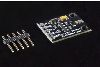
您能否为 BH1750 (光传感器)提供 I2C 接口参考代码?

谢谢。此致、

mounika.

#include <stdbool.h>
#include <stdint.h>
#include "inc/hw_i2c.h"
#include "inc/hw_memmap.h"
#include "inc/hw_types.h"
#include "driverlib/gpio.h"
#include "driverlib/i2c.h"
#include "driverlib/pin_map.h"
#include "driverlib/sysctl.h"
#include "driverlib/uart.h"
#include "utils/uartstdio.h"

#define BH1750_ADDRESS 0x23

void BH1750_Init(void);
void BH1750_Read(uint16_t *lightLevel);

void InitConsole(void)
{
    SysCtlPeripheralEnable(SYSCTL_PERIPH_GPIOB);

    GPIOPinConfigure(GPIO_PB0_U1RX);
    GPIOPinConfigure(GPIO_PB1_U1TX);

    SysCtlPeripheralEnable(SYSCTL_PERIPH_UART1);

    UARTClockSourceSet(UART1_BASE, UART_CLOCK_PIOSC);

    GPIOPinTypeUART(GPIO_PORTB_BASE, GPIO_PIN_0 | GPIO_PIN_1);

    UARTStdioConfig(1, 115200, 16000000);
}

int main(void)
{
    SysCtlClockSet(SYSCTL_SYSDIV_2_5 | SYSCTL_USE_PLL | SYSCTL_OSC_MAIN | SYSCTL_XTAL_16MHZ);
    InitConsole();
    BH1750_Init();

    while (1)
    {
        uint16_t lightLevel;
        BH1750_Read(&lightLevel);

        UARTprintf("Light Level: %d [lx]\n", lightLevel);

        SysCtlDelay(SysCtlClockGet() / 3); // Delay for a while before reading again.
    }
}

void BH1750_Init(void)
{
    SysCtlPeripheralEnable(SYSCTL_PERIPH_GPIOB);
    GPIOPinConfigure(GPIO_PB2_I2C0SCL);
    GPIOPinConfigure(GPIO_PB3_I2C0SDA);

    GPIOPinTypeI2CSCL(GPIO_PORTB_BASE, GPIO_PIN_2);
    GPIOPinTypeI2C(GPIO_PORTB_BASE, GPIO_PIN_3);

    SysCtlDelay(3);

    I2CMasterInitExpClk(I2C0_BASE, SysCtlClockGet(), true);
    I2CMasterSlaveAddrSet(I2C0_BASE, BH1750_ADDRESS, false);
}

void BH1750_Read(uint16_t *lightLevel)
{
    uint8_t data[2];

    // Send a command to start a measurement (e.g., continuous high-resolution mode)
    uint8_t command = 0x20; // Start measurement in continuous high-resolution mode

    I2CMasterControl(I2C0_BASE, I2C_MASTER_CMD_SINGLE_SEND);
    I2CMasterDataPut(I2C0_BASE, command);
    I2CMasterControl(I2C0_BASE, I2C_MASTER_CMD_SINGLE_SEND);
    while (I2CMasterBusy(I2C0_BASE))
    {
    }

    // Wait for the measurement to complete
    SysCtlDelay(SysCtlClockGet() / 10); // Wait for 100ms

    // Read 2 bytes of data
    I2CMasterControl(I2C0_BASE, I2C_MASTER_CMD_BURST_RECEIVE_START);
    while (I2CMasterBusy(I2C0_BASE))
    {
    }
    data[0] = I2CMasterDataGet(I2C0_BASE);

    I2CMasterControl(I2C0_BASE, I2C_MASTER_CMD_BURST_RECEIVE_FINISH);
    while (I2CMasterBusy(I2C0_BASE))
    {
    }
    data[1] = I2CMasterDataGet(I2C0_BASE);

    *lightLevel = (data[0] << 8) | data[1];
}
  • 请注意,本文内容源自机器翻译,可能存在语法或其它翻译错误,仅供参考。如需获取准确内容,请参阅链接中的英语原文或自行翻译。

    上面的代码是我在 CCS 中运行的代码、但调试时代码停止在 bh1750函数调用。

  • 请注意,本文内容源自机器翻译,可能存在语法或其它翻译错误,仅供参考。如需获取准确内容,请参阅链接中的英语原文或自行翻译。

  • 请注意,本文内容源自机器翻译,可能存在语法或其它翻译错误,仅供参考。如需获取准确内容,请参阅链接中的英语原文或自行翻译。

    #include <stdbool.h>
    #include <stdint.h>
    #include "inc/hw_i2c.h"
    #include "inc/hw_memmap.h"
    #include "inc/hw_types.h"
    #include "driverlib/gpio.h"
    #include "driverlib/i2c.h"
    #include "driverlib/pin_map.h"
    #include "driverlib/sysctl.h"
    #include "driverlib/uart.h"
    #include "utils/uartstdio.h"
    
    #define BH1750_ADDRESS 0x23
    //#define BH1750_ADDRESS 0x5C
    
    void BH1750_Init(void);
    void BH1750_Read(uint16_t *lightLevel);
    
    void InitConsole(void)
    {
        // Enable GPIO port B for UART0 pins
        SysCtlPeripheralEnable(SYSCTL_PERIPH_GPIOB);
    
        // Configure UART0 pin muxing for port B pins 0 and 1
        GPIOPinConfigure(GPIO_PB0_U1RX);
        GPIOPinConfigure(GPIO_PB1_U1TX);
    
        // Enable UART0
        SysCtlPeripheralEnable(SYSCTL_PERIPH_UART1);
    
        // Use the internal 16MHz oscillator as the UART clock source
        UARTClockSourceSet(UART1_BASE, UART_CLOCK_PIOSC);
    
        // Select UART function for these pins
        GPIOPinTypeUART(GPIO_PORTB_BASE, GPIO_PIN_0 | GPIO_PIN_1);
    
        // Initialize UART0 for console I/O
        UARTStdioConfig(1, 115200, 16000000);
    }
    
    int main(void)
    {
        // Set the system clock to 80 MHz
        SysCtlClockSet(SYSCTL_SYSDIV_2_5 | SYSCTL_USE_PLL | SYSCTL_OSC_MAIN | SYSCTL_XTAL_16MHZ);
    
        // Initialize the UART for console output
        InitConsole();
    
        // Initialize the I2C communication and BH1750 sensor
        BH1750_Init();
    
        while (1)
        {
            uint16_t lightLevel;
            BH1750_Read(&lightLevel);
    
            // Display the light level via UART
            UARTprintf("Light Level: %d [lx]\n", lightLevel);
    
            // Delay for a while before reading again
            SysCtlDelay(SysCtlClockGet() / 3);
        }
    }
    
    void BH1750_Init(void)
    {
        // Enable GPIO port B for I2C0 pins
        SysCtlPeripheralEnable(SYSCTL_PERIPH_GPIOB);
        SysCtlPeripheralEnable(SYSCTL_PERIPH_I2C0);
        // Configure the pin muxing for I2C0 functions on port B pins 2 and 3
        GPIOPinConfigure(GPIO_PB2_I2C0SCL);
        GPIOPinConfigure(GPIO_PB3_I2C0SDA);
    
        // Set pin types for I2C communication
        GPIOPinTypeI2CSCL(GPIO_PORTB_BASE, GPIO_PIN_2);
        GPIOPinTypeI2C(GPIO_PORTB_BASE, GPIO_PIN_3);
    
        // Initialize the I2C peripheral
        I2CMasterInitExpClk(I2C0_BASE, SysCtlClockGet(), true);
    
        // Set the I2C slave address to BH1750_ADDRESS
        I2CMasterSlaveAddrSet(I2C0_BASE, BH1750_ADDRESS, false);
    }
    
    void BH1750_Read(uint16_t *lightLevel)
    {
        uint8_t data[2];
    
        // Send a command to start a measurement (e.g., continuous high-resolution mode)
        uint8_t command = 0x20; // Start measurement in continuous high-resolution mode
    
        // Send the command to the sensor
        I2CMasterControl(I2C0_BASE, I2C_MASTER_CMD_SINGLE_SEND);
        I2CMasterDataPut(I2C0_BASE, command);
        I2CMasterControl(I2C0_BASE, I2C_MASTER_CMD_SINGLE_SEND);
        while (I2CMasterBusy(I2C0_BASE))
        {
        }
    
        // Wait for the measurement to complete
        SysCtlDelay(SysCtlClockGet() / 100); // Wait for 10ms
    
        // Read 2 bytes of data from the sensor
        I2CMasterControl(I2C0_BASE, I2C_MASTER_CMD_BURST_RECEIVE_START);
        while (I2CMasterBusy(I2C0_BASE))
        {
        }
        data[0] = I2CMasterDataGet(I2C0_BASE);
    
        I2CMasterControl(I2C0_BASE, I2C_MASTER_CMD_BURST_RECEIVE_FINISH);
        while (I2CMasterBusy(I2C0_BASE))
        {
        }
        data[1] = I2CMasterDataGet(I2C0_BASE);
    
        // Combine the two bytes to get the light level
        *lightLevel = (data[0] << 8) | data[1];
    }
    

    更新了 AM 使用的代码

  • 请注意,本文内容源自机器翻译,可能存在语法或其它翻译错误,仅供参考。如需获取准确内容,请参阅链接中的英语原文或自行翻译。

    这里有一些注释。  

    -为什么有93号线? 您是否尝试先向从器件发送命令? 如果是这样、您只需要线路94和95。 您不需要线路93。 当您执行第93行时、您将在 I2C 移位寄存器中没有有效数据时启动 I2C 总线事务。 因此、您需要拆下第93行。 您首先设置要写入第94行的数据、然后执行第95行、以启动 I2C 总线事务。  

    -在第104行,你正在尝试从 I2C 从. 不过、您没有改变方向。 如第82行所示、您仍处于 I2C 写入模式。 在读取数据之前、您需要首先调用   I2CMasterSlaveAddrSet (I2C0_BASE、BH1750_ADDRESS、TRUE)以将 I2C 更改为读取模式。 没有它、将无法正常工作。  

    -为什么不浏览 C:\ti\TivaWare_C_Series-2.2.0.295\examples\boards\ek-tm4c123gxl-boostxl-sensub\HUMIDITY_sht21_simple 中关于如何对简单的 SHT21器件进行 I2C 写入和读取操作的示例? 我们没有  BH1750的示例。 许多 I2C 器件在读取和写入方面相似。 您可以参考此示例。  

     -这里是一个非常有用的 I2C 应用手册,关于如何使用各种命令。https://www.ti.com/lit/pdf/spma073

     -我强烈建议您使用逻辑分析仪或示波器来验证波形。 它可以显著缩短调试时间。  

  • 请注意,本文内容源自机器翻译,可能存在语法或其它翻译错误,仅供参考。如需获取准确内容,请参阅链接中的英语原文或自行翻译。

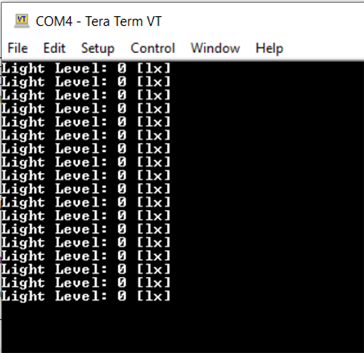
    我对93行进行了注释 和检查 、但 仍然遇到相同的问题。

    #include <stdbool.h>
    #include <stdint.h>
    #include "inc/hw_i2c.h"
    #include "inc/hw_memmap.h"
    #include "inc/hw_types.h"
    #include "driverlib/gpio.h"
    #include "driverlib/i2c.h"
    #include "driverlib/pin_map.h"
    #include "driverlib/sysctl.h"
    #include "driverlib/uart.h"
    #include "utils/uartstdio.h"
    
    #define BH1750_ADDRESS 0x23
    //#define BH1750_ADDRESS 0x5C
    
    void BH1750_Init(void);
    void BH1750_Read(uint16_t *lightLevel);
    
    void InitConsole(void)
    {
        // Enable GPIO port B for UART0 pins
        SysCtlPeripheralEnable(SYSCTL_PERIPH_GPIOB);
    
        // Configure UART0 pin muxing for port B pins 0 and 1
        GPIOPinConfigure(GPIO_PB0_U1RX);
        GPIOPinConfigure(GPIO_PB1_U1TX);
    
        // Enable UART0
        SysCtlPeripheralEnable(SYSCTL_PERIPH_UART1);
    
        // Use the internal 16MHz oscillator as the UART clock source
        UARTClockSourceSet(UART1_BASE, UART_CLOCK_PIOSC);
    
        // Select UART function for these pins
        GPIOPinTypeUART(GPIO_PORTB_BASE, GPIO_PIN_0 | GPIO_PIN_1);
    
        // Initialize UART0 for console I/O
        UARTStdioConfig(1, 115200, 16000000);
    }
    
    int main(void)
    {
        // Set the system clock to 80 MHz
        SysCtlClockSet(SYSCTL_SYSDIV_2_5 | SYSCTL_USE_PLL | SYSCTL_OSC_MAIN | SYSCTL_XTAL_16MHZ);
    
        // Initialize the UART for console output
        InitConsole();
    
        // Initialize the I2C communication and BH1750 sensor
        BH1750_Init();
    
        while (1)
        {
            uint16_t lightLevel;
            BH1750_Read(&lightLevel);
    
            // Display the light level via UART
            UARTprintf("Light Level: %d [lx]\n", lightLevel);
    
            // Delay for a while before reading again
            SysCtlDelay(SysCtlClockGet() / 3);
        }
    }
    
    void BH1750_Init(void)
    {
        // Enable GPIO port B for I2C0 pins
        SysCtlPeripheralEnable(SYSCTL_PERIPH_GPIOB);
        SysCtlPeripheralEnable(SYSCTL_PERIPH_I2C0);
        // Configure the pin muxing for I2C0 functions on port B pins 2 and 3
        GPIOPinConfigure(GPIO_PB2_I2C0SCL);
        GPIOPinConfigure(GPIO_PB3_I2C0SDA);
    
        // Set pin types for I2C communication
        GPIOPinTypeI2CSCL(GPIO_PORTB_BASE, GPIO_PIN_2);
        GPIOPinTypeI2C(GPIO_PORTB_BASE, GPIO_PIN_3);
    
        // Initialize the I2C peripheral
        I2CMasterInitExpClk(I2C0_BASE, SysCtlClockGet(), true);
    
        // Set the I2C slave address to BH1750_ADDRESS
        I2CMasterSlaveAddrSet(I2C0_BASE, BH1750_ADDRESS, false);
    }
    
    void BH1750_Read(uint16_t *lightLevel)
    {
        uint8_t data[2];
    
        // Send a command to start a measurement (e.g., continuous high-resolution mode)
        uint8_t command = 0x20; // Start measurement in continuous high-resolution mode
    
        // Send the command to the sensor
       // I2CMasterControl(I2C0_BASE, I2C_MASTER_CMD_SINGLE_SEND);
        I2CMasterDataPut(I2C0_BASE, command);
        I2CMasterControl(I2C0_BASE, I2C_MASTER_CMD_SINGLE_SEND);
        while (I2CMasterBusy(I2C0_BASE))
        {
        }
    
        // Wait for the measurement to complete
        SysCtlDelay(SysCtlClockGet() / 100); // Wait for 10ms
    
        // Read 2 bytes of data from the sensor
        I2CMasterControl(I2C0_BASE, I2C_MASTER_CMD_BURST_RECEIVE_START);
        while (I2CMasterBusy(I2C0_BASE))
        {
        }
        data[0] = I2CMasterDataGet(I2C0_BASE);
    
        I2CMasterControl(I2C0_BASE, I2C_MASTER_CMD_BURST_RECEIVE_FINISH);
        while (I2CMasterBusy(I2C0_BASE))
        {
        }
        data[1] = I2CMasterDataGet(I2C0_BASE);
    
        // Combine the two bytes to get the light level
        *lightLevel = (data[0] << 8) | data[1];
    }
    

  • 请注意,本文内容源自机器翻译,可能存在语法或其它翻译错误,仅供参考。如需获取准确内容,请参阅链接中的英语原文或自行翻译。

    您是否阅读了我最后一次回复的完整内容?

    我说过第104行有一个问题、您没有将主方向从写入更改为读取。 您处于写入模式、以便首先向从器件发送命令。 您需要更改读取方向才能进行读取。 在快速拒绝我的答案之前、请先浏览我的所有评论。   

    -在第104行,你正在尝试从 I2C 从. 不过、您没有改变方向。 如第82行所示、您仍处于 I2C 写入模式。 在读取数据之前、您需要首先调用   I2CMasterSlaveAddrSet (I2C0_BASE、BH1750_ADDRESS、TRUE)以将 I2C 更改为读取模式。 没有它、将无法正常工作。  

    -为什么不浏览 C:\ti\TivaWare_C_Series-2.2.0.295\examples\boards\ek-tm4c123gxl-boostxl-sensub\HUMIDITY_sht21_simple 中关于如何对简单的 SHT21器件进行 I2C 写入和读取操作的示例? 我们没有 BH1750的示例。 许多 I2C 器件在读取和写入方面相似。 您可以参考此示例。  

     -这里是一个非常有用的 I2C 应用手册,关于如何使用各种命令。https://www.ti.com/lit/pdf/spma073

     -我强烈建议您使用逻辑分析仪或示波器来验证波形。 它可以显著缩短调试时间。  

  • 请注意,本文内容源自机器翻译,可能存在语法或其它翻译错误,仅供参考。如需获取准确内容,请参阅链接中的英语原文或自行翻译。

    您好!

     您有任何更新吗? 您的问题是否得到了解决?

  • 请注意,本文内容源自机器翻译,可能存在语法或其它翻译错误,仅供参考。如需获取准确内容,请参阅链接中的英语原文或自行翻译。

    您好!

     我没有听到你的回应。 我现在将关闭该主题。 如果你有任何更新、你可以回写此帖子、该主题将自动将状态更改为"再次打开"。