请注意,本文内容源自机器翻译,可能存在语法或其它翻译错误,仅供参考。如需获取准确内容,请参阅链接中的英语原文或自行翻译。
器件型号:TM4C123GH6PM 您好!
您能否为 BH1750 (光传感器)提供 I2C 接口参考代码?
谢谢。此致、
mounika.
#include <stdbool.h>
#include <stdint.h>
#include "inc/hw_i2c.h"
#include "inc/hw_memmap.h"
#include "inc/hw_types.h"
#include "driverlib/gpio.h"
#include "driverlib/i2c.h"
#include "driverlib/pin_map.h"
#include "driverlib/sysctl.h"
#include "driverlib/uart.h"
#include "utils/uartstdio.h"
#define BH1750_ADDRESS 0x23
void BH1750_Init(void);
void BH1750_Read(uint16_t *lightLevel);
void InitConsole(void)
{
SysCtlPeripheralEnable(SYSCTL_PERIPH_GPIOB);
GPIOPinConfigure(GPIO_PB0_U1RX);
GPIOPinConfigure(GPIO_PB1_U1TX);
SysCtlPeripheralEnable(SYSCTL_PERIPH_UART1);
UARTClockSourceSet(UART1_BASE, UART_CLOCK_PIOSC);
GPIOPinTypeUART(GPIO_PORTB_BASE, GPIO_PIN_0 | GPIO_PIN_1);
UARTStdioConfig(1, 115200, 16000000);
}
int main(void)
{
SysCtlClockSet(SYSCTL_SYSDIV_2_5 | SYSCTL_USE_PLL | SYSCTL_OSC_MAIN | SYSCTL_XTAL_16MHZ);
InitConsole();
BH1750_Init();
while (1)
{
uint16_t lightLevel;
BH1750_Read(&lightLevel);
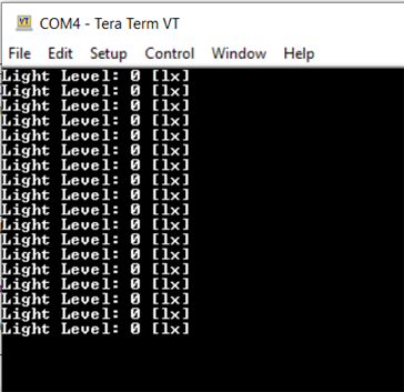
UARTprintf("Light Level: %d [lx]\n", lightLevel);
SysCtlDelay(SysCtlClockGet() / 3); // Delay for a while before reading again.
}
}
void BH1750_Init(void)
{
SysCtlPeripheralEnable(SYSCTL_PERIPH_GPIOB);
GPIOPinConfigure(GPIO_PB2_I2C0SCL);
GPIOPinConfigure(GPIO_PB3_I2C0SDA);
GPIOPinTypeI2CSCL(GPIO_PORTB_BASE, GPIO_PIN_2);
GPIOPinTypeI2C(GPIO_PORTB_BASE, GPIO_PIN_3);
SysCtlDelay(3);
I2CMasterInitExpClk(I2C0_BASE, SysCtlClockGet(), true);
I2CMasterSlaveAddrSet(I2C0_BASE, BH1750_ADDRESS, false);
}
void BH1750_Read(uint16_t *lightLevel)
{
uint8_t data[2];
// Send a command to start a measurement (e.g., continuous high-resolution mode)
uint8_t command = 0x20; // Start measurement in continuous high-resolution mode
I2CMasterControl(I2C0_BASE, I2C_MASTER_CMD_SINGLE_SEND);
I2CMasterDataPut(I2C0_BASE, command);
I2CMasterControl(I2C0_BASE, I2C_MASTER_CMD_SINGLE_SEND);
while (I2CMasterBusy(I2C0_BASE))
{
}
// Wait for the measurement to complete
SysCtlDelay(SysCtlClockGet() / 10); // Wait for 100ms
// Read 2 bytes of data
I2CMasterControl(I2C0_BASE, I2C_MASTER_CMD_BURST_RECEIVE_START);
while (I2CMasterBusy(I2C0_BASE))
{
}
data[0] = I2CMasterDataGet(I2C0_BASE);
I2CMasterControl(I2C0_BASE, I2C_MASTER_CMD_BURST_RECEIVE_FINISH);
while (I2CMasterBusy(I2C0_BASE))
{
}
data[1] = I2CMasterDataGet(I2C0_BASE);
*lightLevel = (data[0] << 8) | data[1];
}