This thread has been locked.

If you have a related question, please click the "Ask a related question" button in the top right corner. The newly created question will be automatically linked to this question.

[参考译文] TM4C123GH6PM:ADC 比较器中断

Guru**** 1838950 points
请注意,本文内容源自机器翻译,可能存在语法或其它翻译错误,仅供参考。如需获取准确内容,请参阅链接中的英语原文或自行翻译。

https://e2e.ti.com/support/microcontrollers/arm-based-microcontrollers-group/arm-based-microcontrollers/f/arm-based-microcontrollers-forum/1382343/tm4c123gh6pm-adc-comparator-interrupt

器件型号:TM4C123GH6PM

工具与软件:

您好!

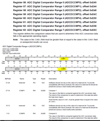
我将尝试实施 ADC 比较器中断、以便在测量的电压高于0.11V 时红色 LED 亮起、并在低于0.11V (约为136/4096 * 3.3V)时熄灭。 下面是我的代码。 我怀疑 InitADC 和 ADC0Seq2Handler 中的中断条件/配置有问题。 我已经正确地更新了 startup_ccs.c 中的矢量表  

#define ADC_SEQUENCER3_LENGTH 1
#define ADC_SEQUENCER2_LENGTH 4
#define ADC_SEQUENCER1_LENGTH 4
#define ADC_SEQUENCER0_LENGTH 8
#define VOLTAGE_PRIORITY 0
#define VOLTAGE_CALIBRATION_FACTOR 1.008

uint32_t VoltBuf[ADC_SEQUENCER2_LENGTH];                        // SS2 has the size of 4 samples
uint32_t voltage;
int32_t VoltIntegerPart;
int32_t VoltFractionPart;

void ADC0Seq2Handler(void){
    IntMasterDisable();
    uint32_t ulStatus = ADCIntStatus(ADC0_BASE, 2, true);
    uint32_t comparatorStatus = ADCComparatorIntStatus(ADC0_BASE);
    ADCIntClear(ADC0_BASE,2);

    if (comparatorStatus & (1 << 0)) {
        GPIOPinWrite(GPIO_PORTF_BASE, GPIO_PIN_2, GPIO_PIN_2);
        ADCComparatorIntClear(ADC0_BASE, 0);
    }
    if (comparatorStatus & (1 << 1)) {
        GPIOPinWrite(GPIO_PORTF_BASE, GPIO_PIN_2, 0);
        ADCComparatorIntClear(ADC0_BASE, 1);
    }
    IntMasterEnable();
}

void InitADC(void){
  SysCtlPeripheralEnable(SYSCTL_PERIPH_GPIOE); 
  GPIOPinTypeADC(GPIO_PORTE_BASE, GPIO_PIN_3);                                                          // Configure PE3 as an ADC input
  SysCtlPeripheralEnable(SYSCTL_PERIPH_ADC0);                                                           // Enable the ADC0 peripheral
  ADCHardwareOversampleConfigure(ADC0_BASE,32);                                                         // Set the auto average to 64

  // Configure sequence 2 for voltage measurement on AIN0 (PE)
  ADCSequenceDisable(ADC0_BASE, 2);                                                                     // Disable sequence 2
  ADCSequenceConfigure(ADC0_BASE, 2, ADC_TRIGGER_PROCESSOR, VOLTAGE_PRIORITY);                          // Configure sequence 2
  ADCSequenceStepConfigure(ADC0_BASE, 2, 0, ADC_CTL_CH0);
  ADCSequenceStepConfigure(ADC0_BASE, 2, 1, ADC_CTL_CH0);
  ADCSequenceStepConfigure(ADC0_BASE, 2, 2, ADC_CTL_CH0);
  ADCSequenceStepConfigure(ADC0_BASE, 2, 3, ADC_CTL_CH0 | ADC_CTL_IE | ADC_CTL_END);                     // Set up the last step and start an interrupt when the conversion is over
  ADCSequenceEnable(ADC0_BASE, 2);                                                                       // Enable the sequence again
  ADCIntEnable(ADC0_BASE,0);
  ADCIntClear(ADC0_BASE, 2);                                                                             // Clear the interrupt flag


  // Configure the ADC comparator
  ADCComparatorConfigure(ADC0_BASE, 1, ADC_COMP_TRIG_NONE | ADC_COMP_INT_HIGH_HALWAYS); ////////////////////////////////////////////////////////////////////////////////// could be wrong
  ADCComparatorRegionSet(ADC0_BASE, 0, 136, 4095); // Set the comparator region (136 corresponds to 0.11V)
  ADCComparatorReset(ADC0_BASE, 0, true, true); // Reset the comparator
  ADCComparatorIntEnable(ADC0_BASE, 0); // Enable the comparator interrupt

  ADCComparatorConfigure(ADC0_BASE, 2, ADC_COMP_TRIG_NONE | ADC_COMP_INT_LOW_HALWAYS ); ////////////////////////////////////////////////////////////////////////////////// could be wrong
  ADCComparatorRegionSet(ADC0_BASE, 1, 0, 136); // Set the comparator region (136 corresponds to 0.11V)
  ADCComparatorReset(ADC0_BASE, 1, true, true); // Reset the comparator
  ADCComparatorIntEnable(ADC0_BASE, 1); // Enable the comparator interrupt

  IntEnable(INT_ADC0SS2); // Enable the ADC sequence 2 interrupt in the NVIC
  IntMasterEnable();
}

void InitGPIO(void) {
    // Enable the GPIO port for the LED (PF2)
    SysCtlPeripheralEnable(SYSCTL_PERIPH_GPIOF);
    GPIOPinTypeGPIOOutput(GPIO_PORTF_BASE, GPIO_PIN_1); // Configure PF2 as an output
    GPIOPinWrite(GPIO_PORTF_BASE, GPIO_PIN_1, 0); // Initialize the LED to be off
}


void main(void) {
    SysCtlClockSet(SYSCTL_SYSDIV_2_5 | SYSCTL_USE_PLL | SYSCTL_OSC_MAIN | SYSCTL_XTAL_16MHZ); // System clock: 16*12.5/2.5 = 80MHz (MAX)
    InitADC();
    InitGPIO();
    while(1){}
}


现在、PE3正在收集电压数据、我已确认它工作正常。 怎么了?

  • 请注意,本文内容源自机器翻译,可能存在语法或其它翻译错误,仅供参考。如需获取准确内容,请参阅链接中的英语原文或自行翻译。

    顺便说一下、第44行应该是 ADCIntEnable (ADC0_BASE、2)

  • 请注意,本文内容源自机器翻译,可能存在语法或其它翻译错误,仅供参考。如需获取准确内容,请参阅链接中的英语原文或自行翻译。

    实际上、这杀死了我拥有的其余主要功能。

  • 请注意,本文内容源自机器翻译,可能存在语法或其它翻译错误,仅供参考。如需获取准确内容,请参阅链接中的英语原文或自行翻译。

    假设您要将 AIN0传递给比较器0进行比较、您将编写如下内容。  

    ADCSequenceStepConfigure (ADC0_BASE、2、0、ADC_CTL_CH0 | ADC_CTL_CMP0);//将 CH0分配至步骤0并将该通道路由到比较器0。  

    在代码中、我看到使用比较器1和比较器2来检查边界时、没有向任何比较器分配任何通道。 请记住 、与每个比较器单元关联、您可以设置上下键合值。 请参阅以下说明。 无需使用两个不同的比较器单元来设置上限和下限。 您似乎打算使用两个不同的比较器单元来设置两个不同的限值。 在另一种情况下,您只需将通道(例如 CH0)分配给比较器(例如  ADC_CTL_CMP0)  并设置  ADC_CTL_CMP0比较器的下限和上限。  


  • 请注意,本文内容源自机器翻译,可能存在语法或其它翻译错误,仅供参考。如需获取准确内容,请参阅链接中的英语原文或自行翻译。

    感谢您的答复。 更新后的代码如下所示。 它仍然不工作,我不知道什么是错的。 我一直在遵循这里显示的示例代码: https://e2e.ti.com/support/microcontrollers/arm-based-microcontrollers-group/arm-based-microcontrollers/f/arm-based-microcontrollers-forum/313435/tiva-digital-comparator-problem

    但他们的示例似乎没有内部温度传感器读数、我的示例中没有、我不知道我的设置的哪个部分是错误的。 顺便说一下、如果我运行以下代码、可以在终端上得到正确的输出。 只有 ADC 中断不起作用。  

    #define ADC_SEQUENCER3_LENGTH 1
    #define ADC_SEQUENCER2_LENGTH 4
    #define ADC_SEQUENCER1_LENGTH 4
    #define ADC_SEQUENCER0_LENGTH 8
    
    #define VOLTAGE_CALIBRATION_FACTOR 1.008
    
    int ulTemp_ValueC;
    uint32_t TempBuf[ADC_SEQUENCER3_LENGTH];                        // SS3 has the size of 1 sample
    uint32_t VoltBuf[ADC_SEQUENCER2_LENGTH];                        // SS2 has the size of 4 samples
    
    int tempC;
    int tempF;
    uint32_t voltage;
    int32_t VoltIntegerPart;
    int32_t VoltFractionPart;
    
    void InitUART(void){
        // Initialize the UART.
    
        SysCtlPeripheralEnable(SYSCTL_PERIPH_GPIOA);
        SysCtlPeripheralEnable(SYSCTL_PERIPH_UART0);
        GPIOPinConfigure(GPIO_PA0_U0RX);
        GPIOPinConfigure(GPIO_PA1_U0TX);
        GPIOPinTypeUART(GPIO_PORTA_BASE, GPIO_PIN_0 | GPIO_PIN_1);
        UARTClockSourceSet(UART0_BASE, UART_CLOCK_PIOSC);
        UARTStdioConfig(0, 115200,  16000000);
    }
    
    void InitADC(void){
      SysCtlPeripheralEnable(SYSCTL_PERIPH_GPIOE);
      GPIOPinTypeADC(GPIO_PORTE_BASE, GPIO_PIN_3);                                                          // Configure PE3 as an ADC input
      SysCtlPeripheralEnable(SYSCTL_PERIPH_ADC0);                                                           // Enable the ADC0 peripheral
      ADCHardwareOversampleConfigure(ADC0_BASE,32);                                                         // Set the auto average to 64
    
      // Configure sequence 3 for internal temperature sensor
      ADCSequenceDisable(ADC0_BASE, 3); // Disable sequence 3
      ADCSequenceStepConfigure(ADC0_BASE, 3, 0, ADC_CTL_TS | ADC_CTL_IE | ADC_CTL_END); // Set up the last step and start an interrupt when the conversion is over
      ADCSequenceEnable(ADC0_BASE, 3); // Enable the sequence again
      ADCSequenceConfigure(ADC0_BASE, 3, ADC_TRIGGER_PROCESSOR, 1); // Configure sequence 3, Priority must be 1 or 0 if ADC_TRIGGER_ALWAYS is used by another sequence
      ADCIntClear(ADC0_BASE, 3); // Clear the interrupt flag
    
      // Configure sequence 2 for voltage measurement on AIN0 (PE)
      ADCSequenceDisable(ADC0_BASE, 2);                                                                     // Disable sequence 2
      ADCSequenceStepConfigure(ADC0_BASE, 2, 0, ADC_CTL_CH0 | ADC_CTL_CMP0);
      ADCSequenceStepConfigure(ADC0_BASE, 2, 1, ADC_CTL_CH0);
      ADCSequenceStepConfigure(ADC0_BASE, 2, 2, ADC_CTL_CH0);
      ADCSequenceStepConfigure(ADC0_BASE, 2, 3, ADC_CTL_CH0 | ADC_CTL_IE | ADC_CTL_END);                     // Set up the last step and start an interrupt when the conversion is over
      ADCSequenceEnable(ADC0_BASE, 2);                                                                       // Enable the sequence again
      ADCSequenceConfigure(ADC0_BASE, 2, ADC_TRIGGER_ALWAYS, 3);                          // Configure sequence 2
      IntPrioritySet(INT_ADC0SS2, 0);
    //  ADCIntEnable(ADC0_BASE, 2);
      ADCIntEnableEx(ADC0_BASE, ADC_INT_DCON_SS2);
      ADCIntClear(ADC0_BASE, 2);                                                                             // Clear the interrupt flag
    
    
      // Configure the ADC comparator
      ADCComparatorConfigure(ADC0_BASE, 0, ADC_COMP_INT_MID_ONCE);
      ADCComparatorRegionSet(ADC0_BASE, 0, 136, 4095); // Set the comparator region (136 corresponds to 0.11V)
      ADCComparatorReset(ADC0_BASE, 0, true, true); // Reset the comparator
      ADCComparatorIntEnable(ADC0_BASE, 2); // Enable the comparator interrupt
    
      IntEnable(INT_ADC0SS2); // Enable the ADC sequence 2 interrupt in the NVIC
      IntMasterEnable();
    }
    
    void InitGPIO(void) {
        // Enable the GPIO port for the LED (PF2)
        SysCtlPeripheralEnable(SYSCTL_PERIPH_GPIOF);
        GPIOPinTypeGPIOOutput(GPIO_PORTF_BASE, GPIO_PIN_1); // Configure PF2 as an output
        GPIOPinWrite(GPIO_PORTF_BASE, GPIO_PIN_1, 0); // Initialize the LED to be off
    }
    
    
    int GetInternalTemp(void){
        ADCProcessorTrigger(ADC0_BASE, 3);                                 // Trigger the ADC conversion process.
        while(!ADCIntStatus(ADC0_BASE, 3, false)) {}                       // Wait for the interrupt flag to get set
        ADCIntClear(ADC0_BASE, 3);                                         // Clear the interrupt flag
        ADCSequenceDataGet(ADC0_BASE, 3, TempBuf);                     // Get the actual data samples from ADC0 sequencer 3
    
        // Convert the value to temperature
        // TEMP = 147.5 - ((75 * (VREFP - VREFN) * ADCVALUE) / 4096)
        // 3.3V * 10 * 75 = 2475 //13.3.6 of the TM4C123GH6PM datasheet
        ulTemp_ValueC = (1475 -((2475 * TempBuf[0])) / 4096)/10;
    
        return ulTemp_ValueC;
    }
    
    uint32_t GetVoltage(void){
        uint32_t ulADC0Value[1];
    
        ADCProcessorTrigger(ADC0_BASE, 2); // Trigger the ADC conversion process
        while(!ADCIntStatus(ADC0_BASE, 2, false)) {} // Wait for the interrupt flag to get set
        ADCIntClear(ADC0_BASE, 2); // Clear the interrupt flag
        ADCSequenceDataGet(ADC0_BASE, 2, VoltBuf); // Get the actual data samples from ADC0 sequencer 2
    
        ulADC0Value[0] = (VoltBuf[0] + VoltBuf[1] + VoltBuf[2] + VoltBuf[3] + 2)/4;
        return ulADC0Value[0];
    }
    
    void IntToFloat(uint32_t intV){
        float fVoltage;
    
        fVoltage = (intV * 3.3)/4096 * VOLTAGE_CALIBRATION_FACTOR;
        VoltIntegerPart = (int32_t) fVoltage;
        VoltFractionPart = (int32_t) (fVoltage * 1000.0f);
        VoltFractionPart = VoltFractionPart - (VoltIntegerPart * 1000);
        if (VoltFractionPart < 0){
            VoltFractionPart *= -1;
        }
    }
    
    void ADC0Seq2Handler(void){
     //   IntMasterDisable();
     //   uint32_t ulStatus = ADCIntStatus(ADC0_BASE, 2, true);
     //   uint32_t comparatorStatus = ADCComparatorIntStatus(ADC0_BASE);
        uint32_t status;
    
        status = ADCComparatorIntStatus(ADC0_BASE);
    
    
        ADCComparatorIntClear(ADC0_BASE, status);
    
        if ((ADCSequenceDataGet(ADC0_BASE, 2, VoltBuf) >= 136) & status) {
            GPIOPinWrite(GPIO_PORTF_BASE, GPIO_PIN_1, GPIO_PIN_1);
        }
        if ((ADCSequenceDataGet(ADC0_BASE, 2, VoltBuf) < 136) & status) {
            GPIOPinWrite(GPIO_PORTF_BASE, GPIO_PIN_1, 0);
        }
    }
    
    void main(void) {
        SysCtlClockSet(SYSCTL_SYSDIV_2_5 | SYSCTL_USE_PLL | SYSCTL_OSC_MAIN | SYSCTL_XTAL_16MHZ); // System clock: 16*12.5/2.5 = 80MHz (MAX)
    
        InitGPIO(); //// change later
        InitADC();
        InitUART();
        
        while(1){
            tempC = GetInternalTemp();
            tempF = (1.8 * ulTemp_ValueC) + 32;                            // Celsius to Fahrenheit
    
            voltage = GetVoltage();
            IntToFloat(voltage);
            UARTprintf("Voltage = %3d.%03dV\n", VoltIntegerPart, VoltFractionPart);
        
            UARTprintf("Temperature = %3d°C / %3d°F\n", tempC, tempF);
            SysCtlDelay(SysCtlClockGet() / 3); // Delay for about 2 seconds
        }
    }


  • 请注意,本文内容源自机器翻译,可能存在语法或其它翻译错误,仅供参考。如需获取准确内容,请参阅链接中的英语原文或自行翻译。
    但他们的示例似乎没有内部温度传感器读数、我的却没有、

    您好!

     请注意 与温度传感器读数相关的 ADC 勘误表。  

    顺便说一句、如果我运行以下代码、我可以在终端上获得正确的输出。 仅 ADC 中断无法正常工作。[/QUOT]

    另请参阅以下勘误表。


  • 请注意,本文内容源自机器翻译,可能存在语法或其它翻译错误,仅供参考。如需获取准确内容,请参阅链接中的英语原文或自行翻译。

    Scott、您好!

     此问题是否已得到解决? 我现在将结束该主题。 如果您有任何更新、您可以再次写入此帖子、该主题将使其状态更改为"已打开"。