请注意,本文内容源自机器翻译,可能存在语法或其它翻译错误,仅供参考。如需获取准确内容,请参阅链接中的英语原文或自行翻译。
器件型号:EK-TM4C129EXL 主题中讨论的其他器件:UNIFLASH、
工具与软件:
我一直在使用 uniflash 使用一些示例程序对 EK-TM4C129EXL 开发板进行编程、但这种方法已经奏效了几天。 然而、Uniflash 今天突然停止工作、只给我一个错误:"Cortex_M4_0:连接到目标时出错"。 同样、我无法在 CCS 中使用调试功能在调试模式下运行代码。
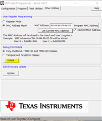
我已经尝试使用 uniflash 对第二个相同的开发板进行编程、这可以正常工作。 我怀疑我可能损坏了电路板上的某些部件、因为我要测试的最后一件事是尝试将 ALTCLK 设置为 RTCOSC。 是否可以 通过错误配置 MCU 来使 EK-TM4C129EXL 开发板不可擦除? 有什么建议可以从这种情况中恢复?
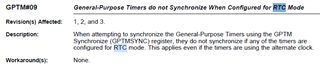
这是我在 MCU 停止响应前刷写的代码。 该方法基于 Tivaware SDK 中的 timers.c 示例、但我已经对其进行修改、因为我尝试使用通用计时器来驱动 PWM 输出引脚、而且我尝试使用 RTCOSC 作为计时器的时钟。
//*****************************************************************************
//
// timers.c - Timers example.
//
// Copyright (c) 2013-2020 Texas Instruments Incorporated.  All rights reserved.
// Software License Agreement
//
// Texas Instruments (TI) is supplying this software for use solely and
// exclusively on TI's microcontroller products. The software is owned by
// TI and/or its suppliers, and is protected under applicable copyright
// laws. You may not combine this software with "viral" open-source
// software in order to form a larger program.
//
// THIS SOFTWARE IS PROVIDED "AS IS" AND WITH ALL FAULTS.
// NO WARRANTIES, WHETHER EXPRESS, IMPLIED OR STATUTORY, INCLUDING, BUT
// NOT LIMITED TO, IMPLIED WARRANTIES OF MERCHANTABILITY AND FITNESS FOR
// A PARTICULAR PURPOSE APPLY TO THIS SOFTWARE. TI SHALL NOT, UNDER ANY
// CIRCUMSTANCES, BE LIABLE FOR SPECIAL, INCIDENTAL, OR CONSEQUENTIAL
// DAMAGES, FOR ANY REASON WHATSOEVER.
//
// This is part of revision 2.2.0.295 of the EK-TM4C1294XL Firmware Package.
//
//*****************************************************************************

#include <stdint.h>
#include <stdbool.h>
#include "inc/hw_ints.h"
#include "inc/hw_memmap.h"
#include "inc/hw_types.h"
#include "driverlib/debug.h"
#include "driverlib/fpu.h"
#include "driverlib/gpio.h"
#include "driverlib/interrupt.h"
#include "driverlib/pin_map.h"
#include "driverlib/rom.h"
#include "driverlib/rom_map.h"
#include "driverlib/sysctl.h"
#include "driverlib/timer.h"
#include "driverlib/uart.h"
#include "utils/uartstdio.h"

//*****************************************************************************
//
//! \addtogroup example_list
//! <h1>Timer (timers)</h1>
//!
//! This example application demonstrates the use of the timers to generate
//! periodic interrupts.  One timer is set up to interrupt once per second and
//! the other to interrupt twice per second; each interrupt handler will toggle
//! its own indicator throught the UART.
//!
//! UART0, connected to the Virtual Serial Port and running at 115,200, 8-N-1,
//! is used to display messages from this application.
//
//*****************************************************************************

//****************************************************************************
//
// System clock rate in Hz.
//
//****************************************************************************
uint32_t g_ui32SysClock;

//*****************************************************************************
//
// Flags that contain the current value of the interrupt indicator as displayed
// on the UART.
//
//*****************************************************************************
uint32_t g_ui32Flags;

//*****************************************************************************
//
// The error routine that is called if the driver library encounters an error.
//
//*****************************************************************************
#ifdef DEBUG
void
__error__(char *pcFilename, uint32_t ui32Line)
{
}
#endif

//*****************************************************************************
//
// Configure the UART and its pins.  This must be called before UARTprintf().
//
//*****************************************************************************
void
ConfigureUART(void)
{
    //
    // Enable the GPIO Peripheral used by the UART.
    //
    MAP_SysCtlPeripheralEnable(SYSCTL_PERIPH_GPIOA);

    //
    // Enable UART0.
    //
    MAP_SysCtlPeripheralEnable(SYSCTL_PERIPH_UART0);

    //
    // Configure GPIO Pins for UART mode.
    //
    MAP_GPIOPinConfigure(GPIO_PA0_U0RX);
    MAP_GPIOPinConfigure(GPIO_PA1_U0TX);
    MAP_GPIOPinTypeUART(GPIO_PORTA_BASE, GPIO_PIN_0 | GPIO_PIN_1);

    //
    // Initialize the UART for console I/O.
    //
    UARTStdioConfig(0, 115200, g_ui32SysClock);
}

//*****************************************************************************
//
// This example application demonstrates the use of the timers to generate
// periodic interrupts.
//
//*****************************************************************************
int
main(void)
{
    //
    // Run from the PLL at 120 MHz.
    // Note: SYSCTL_CFG_VCO_240 is a new setting provided in TivaWare 2.2.x and
    // later to better reflect the actual VCO speed due to SYSCTL#22.
    //
    g_ui32SysClock = MAP_SysCtlClockFreqSet((SYSCTL_XTAL_25MHZ |
                                             SYSCTL_OSC_MAIN |
                                             SYSCTL_USE_PLL |
                                             SYSCTL_CFG_VCO_240), 120000000);

    //
    // Initialize the UART and write status.
    //
    ConfigureUART();

    UARTprintf("\033[2JTimers example\n");
    UARTprintf("T1: 0  T2: 0");

    //
    // Enable the GPIO port that is used for the on-board LEDs.
    //
    MAP_SysCtlPeripheralEnable(SYSCTL_PERIPH_GPION);
    MAP_SysCtlPeripheralEnable(SYSCTL_PERIPH_GPIOD);
    MAP_GPIOPinTypeGPIOOutput(GPIO_PORTN_BASE, GPIO_PIN_0 | GPIO_PIN_1);
    GPIOPinConfigure(GPIO_PD0_T0CCP0);
    GPIOPinTypeTimer(GPIO_PORTD_BASE, GPIO_PIN_0);


    //
    // Enable the peripherals used by this example.
    //
    MAP_SysCtlPeripheralEnable(SYSCTL_PERIPH_TIMER0);     // this one will be used as a PWM


    SysCtlAltClkConfig(SYSCTL_ALTCLK_RTCOSC);
    TimerClockSourceSet(TIMER0_BASE, SYSCTL_ALTCLK_RTCOSC);

    //
    // Configure the two 32-bit periodic timers.
    //
    MAP_TimerConfigure(TIMER0_BASE, (TIMER_CFG_SPLIT_PAIR |TIMER_CFG_A_PWM ));
    MAP_TimerLoadSet(TIMER0_BASE, TIMER_A, 65535);
    MAP_TimerMatchSet(TIMER0_BASE, TIMER_A, 65535/2);

    MAP_TimerPrescaleSet(TIMER0_BASE, TIMER_A, 0);
    MAP_TimerPrescaleMatchSet(TIMER0_BASE, TIMER_A, 0);

    //
    // Enable the timers.
    //
    MAP_TimerEnable(TIMER0_BASE, TIMER_A);


    //
    // Loop forever while the timer runs.
    //
    while(1)
    {
    }
}