请注意,本文内容源自机器翻译,可能存在语法或其它翻译错误,仅供参考。如需获取准确内容,请参阅链接中的英语原文或自行翻译。
器件型号:MSPM0G3507 工具与软件:
您好!
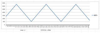
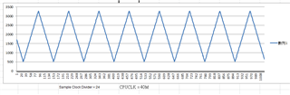
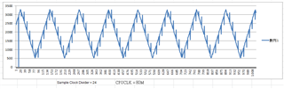
当我使用 ADC 来收集值时、有一些事情发生:当采样时钟分频器= 1或2时、一切看起来正常。 但当采样时钟分频器= 24时、我收到一些噪声、正常情况下的图片如下所示。 同时还有一件有趣的事情。 如果我将 CPUCLK 减少到40M、无论采样时钟分频器是什么、都是正常的。 原因是什么? 我如何考虑 CPUCLK = 80M 和采样时钟分频器= 24? ? ADC 时钟源为 ULPCLK
感谢您的帮助