工具/软件:
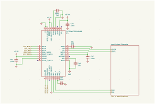
MCLK= 12.288MHz、fs = 48kHz、IOVDD = 3.3V、LDO_IN = 3.3V、AVdd = GND、 DVDD=GND、CM=0.75V
我成功通过 i2c 配置编解码器、但无法使编解码器回放 I2S。 我甚至无法在输出/输入引脚上测量配置的0.75V CM、因此我想编解码器未处于正确的配置中。
这是我当前的配置:
void codec_init(){
    /* ---------- switch to page 0 ---------- */
    codec_write_reg(0x00, 0x00);

    // software reset
    codec_write_reg(0x01, 0x01);

    /*---- Clock and Interface Settings ----*/
    // for Fs = 48KHz nad MCLK = 12.228MHz
    // Fs = MCLK/(NDAC * MDAC * OSR)
    // 48kHz = 12.288MHz/(1 * 2 * 128)


    // NDAC divider = 1
    codec_write_reg(0x0b, 0x81);
    // MDAC divider = 2
    codec_write_reg(0x0c, 0x82);

    // Power up NADC divider with value 1
    codec_write_reg(0x12, 0x81);

    // Power up MADC divider with value 2
    codec_write_reg(0x13, 0x82);

    // OSR of DAC = 128
    codec_write_reg(0x0d, 0x00);
    codec_write_reg(0x0e, 0x80);

    // OSR of ADC = 128
    codec_write_reg(0x14, 0x80);

    // set i2s mode
    // set word length/frame size to 32bit to send 24bit audio data
    // b00110000
    codec_write_reg(0x1b, 0x00);

    // set the DAC Mode to PRB_P8
    // codec_write_reg(0x3c, 0x08);

    // Select DAC PRB_P1
    codec_write_reg(0x3c, 0x01);

    // Select ADC PRB_R1
    codec_write_reg(0x3D, 0x01);

    // Select ADC PTM_R4
    codec_write_reg(0x3D, 0x00);

    // Set MicPGA startup delay to 3.1ms
    codec_write_reg(0x47, 0x32);


    /*---- Configure Power Supplies ----*/

    /* ---------- switch to page 1 ---------- */
    codec_write_reg(0x00, 0x01);

    // Disable weak AVDD-DVDD link
    codec_write_reg(0x01, 0x08);

    // Power AVDD LDO
    codec_write_reg(0x02, 0x01);

    // set REF charging time to 40ms
    codec_write_reg(0x7b, 0x01);

    // HP soft stepping settings for optimal pop performance at power up
    // Rpop used is 6k with N = 6 and soft step = 20usec. This should work with 47uF coupling
    // capacitor. Can try N=5,6 or 7 time constants as well. Trade-off delay vs “pop” sound
    codec_write_reg(0x14, 0x25);

    // D7   = 0     reserved
    // D6   = 1     common mode to 0.75V
    // D4-5 = 00    Output Common Mode for HPL and HPR is same as full-chip common mode
    // D3   = 0     Output Common Mode for LOL and LOR is same as full-chip common mode
    // D2   = 0     reserved
    // D1   = 1     Power HP by LDOIN
    // D0   = 1     LDOIN pin range 1.8V - 3.6V
    //
    // 01000011 = 0x43
    codec_write_reg(0x0a, 0x43);

    /* ---- Routing ----*/

    // route dac to line outs
    // left channel
    codec_write_reg(0x0e, 0x08);
    // right channel
    codec_write_reg(0x0f, 0x08);

    // Route LINE_IN Left to LEFT_P with 20K input impedance
    codec_write_reg(0x34, 0x80);
    // Route LINE_IN Right to RIGHT_P with 20K input impedance
    codec_write_reg(0x37, 0x80);  // Use appropriate register for LINE_IN routing


    // unmute line outs
    // LOL: unmute, 0 dB gain
    codec_write_reg(0x12, 0x00);
    // LOR: unmute, 0 dB gain
    codec_write_reg(0x13, 0x00);

    // Power up LOL and LOR drivers
	codec_write_reg(0x09, 0x3C);

    /* ---------- switch to page 0 ---------- */
    codec_write_reg(0x00, 0x00);

    // DACL DACR -> 0dB
    codec_write_reg(0x41, 0x00);
    codec_write_reg(0x42, 0x00);

    //  Power up the Left and Right DAC Channels with route the Left Audio digital data to
    // Left Channel DAC and Right Audio digital data to Right Channel DAC
    // 11010101
    codec_write_reg(0x3f, 0xd5);

    // unmute dac digital volume control
    codec_write_reg(0x40, 0x00);

    // Power up Left and Right ADC Channels
    // Do not use digital mic
    codec_write_reg(0x51, 0xF0);

    // Unmute Left and Right ADC Digital Volume Control
    codec_write_reg(0x52, 0x00);
}
也许关于输入级的另一个有趣的信息是:
输入似乎处于悬空状态。 我的耦合电容器没有通过交流信号。 此外、我的运算放大器电路的作用类似于具有浮动输出(正弦信号失真到方波)。
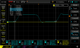
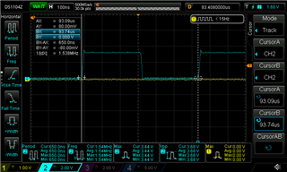
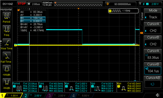
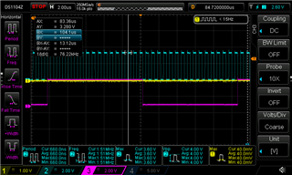
也许我的 MCLK 的信号完整性不是很完美、我会有一点过冲/下冲、但这应该起作用?
如果 MCLK 没有正确地为系统提供时钟、编解码器是否不会应用电源和路由配置?
感谢您的参与:>

