This thread has been locked.

If you have a related question, please click the "Ask a related question" button in the top right corner. The newly created question will be automatically linked to this question.

[参考译文] TLV320AIC3254EVM-K:使用 PurePath Studio 测试滤波器时遇到问题

Guru**** 2782615 points
请注意,本文内容源自机器翻译,可能存在语法或其它翻译错误,仅供参考。如需获取准确内容,请参阅链接中的英语原文或自行翻译。

https://e2e.ti.com/support/audio-group/audio/f/audio-forum/1608443/tlv320aic3254evm-k-trouble-testing-filters-using-purepath-studio

器件型号: TLV320AIC3254EVM-K

您好:  

我们一直在尝试使用 PurePath Studio 在 AIC3254EVM-K 上测试带通滤波器。 这是我们到目前为止尝试的两种配置:

 image.png

image.png

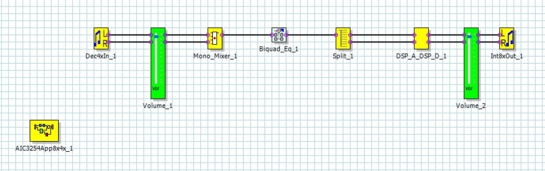
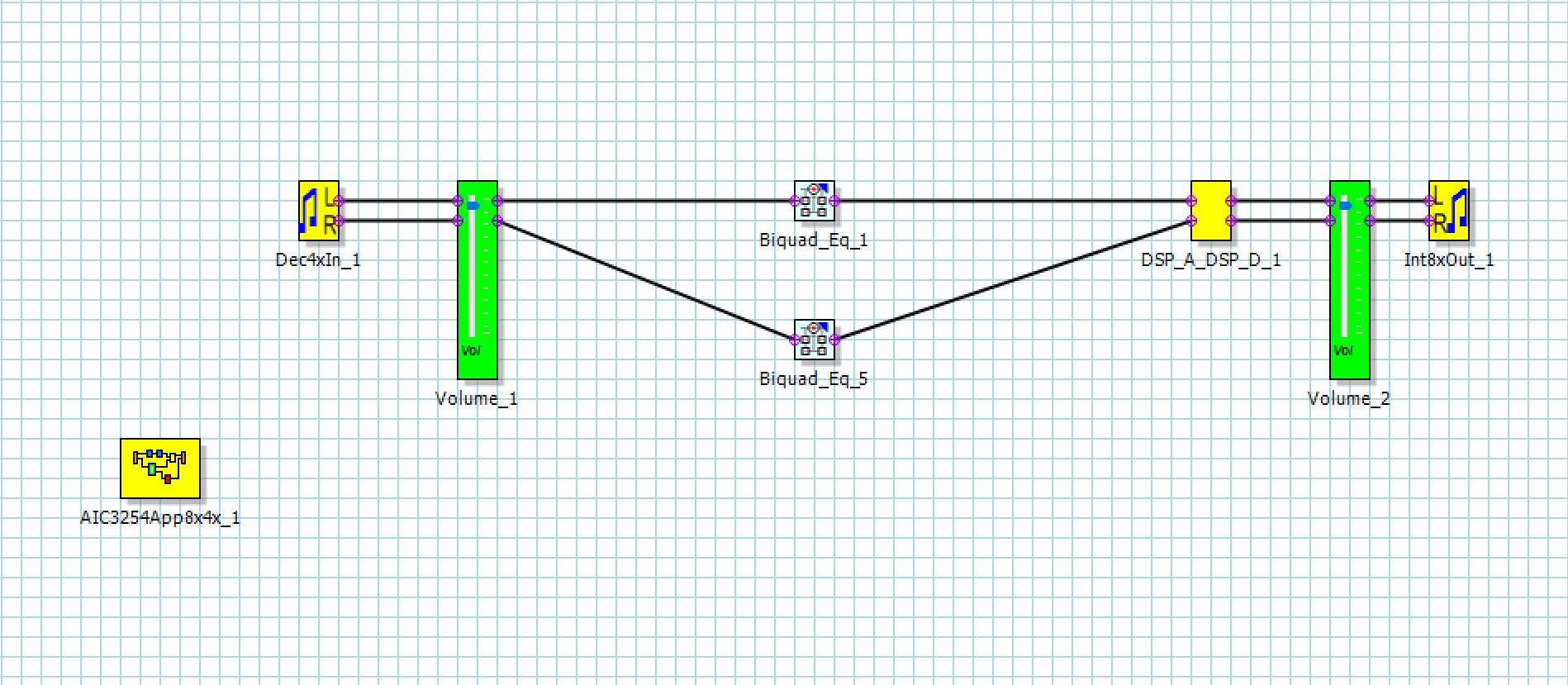
我们一直在尝试使用单通道级联双二阶滤波器块实现频率范围为 500Hz 至 1000Hz 的带通滤波器。  

当我们从板载麦克风获取输入时、即使使用带通滤波器、我们也可以听到频率范围为 200Hz 至 17kHz 的声音。  

我们还尝试使用函数发生器向 IN3_L 和 GND 提供正弦波输入、并通过端口 J8 观察示波器上的输出频率、但在应用带通滤波器时、我们一直获得一条平坦的线作为输出(使用 FIR 滤波器块获得相同的结果,在实施低通滤波器后获得相同的结果。)  

我们只能在滤波器块设置为全通时观察到正确的输出。  

请检查流程图是否正确、以及是否存在对测试的任何误解。  

  • 请注意,本文内容源自机器翻译,可能存在语法或其它翻译错误,仅供参考。如需获取准确内容,请参阅链接中的英语原文或自行翻译。

    您好、

    您能否在 PPS 的“系统设置代码“部分中分享您正在使用的内容? 另外、您是否正在运行“构建“->"下载“下载并运行“? 您还需要做的是启用“SynchMode",“,这、这将允许 ADC 和 DAC 内部时钟以相同的频率运行、因此在 ADC 和 DAC 之间传递 DSP 信息时不会出现音频问题。

    此致、
    Mir

  • 请注意,本文内容源自机器翻译,可能存在语法或其它翻译错误,仅供参考。如需获取准确内容,请参阅链接中的英语原文或自行翻译。

    您好、  

    是的、我使用的是 Build -> Download and Run、并且我还启用了“SyncMode"。“。  

    共享我的系统设置代码如下:

    ;-----------------------------------------------------------------------------------
    ; Software Reset
    ;-----------------------------------------------------------------------------------
    reg[ 0][ 1] = 0x01 ; Initialize the device through software reset
    reg[254][ 0] = 0x0a ; Delay 10ms
    
    ;-----------------------------------------------------------------------------------
    ; Configure Power Supplies
    ;-----------------------------------------------------------------------------------
    %%if (%%prop(TargetBoard) == 2)
    ; AIC3254EVM-U specific configuration
    
    reg[ 1][ 2] = 0xa9 ; Power up AVDD LDO
    reg[ 1][ 1] = 0x08 ; Disable weak AVDD to DVDD connection
    reg[ 1][ 2] = 0xa1 ; Enable Master Analog Power Control, AVDD LDO Powered
    
    %%else
    ; AIC3254EVM-K specific configuration
    reg[ 1][ 1] = 0x08 ; Disable weak AVDD to DVDD connection
    reg[ 1][ 2] = 0x00 ; Enable Master Analog Power Control
    
    %%endif
    
    reg[ 1][ 71] = 0x32 ; Set the input power-up time to 3.1ms
    reg[ 1][123] = 0x01 ; Set REF charging time to 40ms (automatic)
    ; reg[254][0] = 0x28 ; Delay 40ms for REF to Power Up
    
    ;-----------------------------------------------------------------------------------
    ; Load miniDSP Code
    ;-----------------------------------------------------------------------------------
    PROGRAM_ADC ; miniDSP_A coefficients and instructions
    PROGRAM_DAC ; miniDSP_D coefficients and instructions
    
    ;-----------------------------------------------------------------------------------
    ; Signal Processing Settings
    ;-----------------------------------------------------------------------------------
    %%if (%%prop(SynchMode) == 1)
    ; SynchMode is enabled
    reg[ 0][ 60] = 0x80 ; DAC prog Mode: miniDSP_A and miniDSP_D ARE powered up together, miniDSP_A used for signal processing
    %%else
    ; SynchMode is disabled
    reg[ 0][ 60] = 0x00 ; DAC prog Mode: miniDSP_A and miniDSP_D NOT powered up together, miniDSP_A used for signal processing
    %%endif
    reg[ 0][ 61] = 0x00 ; Use miniDSP_A for signal processing
    
    %%if ("%%prop(FrameworkType)" == "AIC3254App8x4x")
    reg[ 0][ 17] = 0x08 ; 8x Interpolation
    reg[ 0][ 23] = 0x04 ; 4x Decimation
    %%endif
    
    %%if ("%%prop(FrameworkType)" == "AIC3254App4x2x")
    reg[ 0][ 17] = 0x04 ; 4x Interpolation
    reg[ 0][ 23] = 0x02 ; 2x Decimation
    %%endif
    
    %%if ("%%prop(FrameworkType)" == "AIC3254App2x1x")
    reg[ 0][ 17] = 0x02 ; 2x Interpolation
    reg[ 0][ 23] = 0x01 ; 1x Decimation
    %%endif
    
    IDAC = %%prop(miniDSP_D_Cycles)
    IADC = %%prop(miniDSP_A_Cycles)
    
    %%if (%%prop(miniDSP_A_Adaptive) == 1)
    reg[ 8][ 1] = 0x04 ; adaptive mode for ADC
    %%endif
    
    %%if (%%prop(miniDSP_D_Adaptive) == 1)
    reg[ 44][ 1] = 0x04 ; adaptive mode for DAC
    %%endif
    
    ;-----------------------------------------------------------------------------------
    ; Clock and Interface Configuration
    ;-----------------------------------------------------------------------------------
    ; USB Audio supports 8kHz to 48kHz sample rates
    ; An external audio interface is required for 88.2kHz to 192kHz sample rates
    ;-----------------------------------------------------------------------------------
    %%if (%%prop(SampleRate) == 176400 || %%prop(SampleRate) == 192000)
    reg[ 0][ 5] = 0x91 ; P=1, R=1, J=8
    reg[ 0][ 6] = 0x08 ; P=1, R=1, J=8
    reg[ 0][ 7] = 0x00 ; D=0000 (MSB)
    reg[ 0][ 8] = 0x00 ; D=0000 (LSB)
    reg[ 0][ 4] = 0x03 ; PLL_clkin = MCLK, codec_clkin = PLL_CLK, PLL on
    reg[ 0][ 12] = 0x88 ; MDAC = 8, divider powered on
    reg[ 0][ 13] = 0x00 ; DOSR = 32 (MSB)
    reg[ 0][ 14] = 0x20 ; DOSR = 32 (LSB)
    reg[ 0][ 18] = 0x02 ; NADC = 2, divider powered off
    reg[ 0][ 19] = 0x88 ; MADC = 8, divider powered on
    reg[ 0][ 20] = 0x20 ; AOSR = 32
    reg[ 0][ 11] = 0x82 ; NDAC = 2, divider powered on
    
    %%endif
    
    %%if (%%prop(SampleRate) == 88200 || %%prop(SampleRate) == 96000)
    reg[ 0][ 5] = 0x91 ; P=1, R=1, J=8
    reg[ 0][ 6] = 0x08 ; P=1, R=1, J=8
    reg[ 0][ 7] = 0x00 ; D=0000 (MSB)
    reg[ 0][ 8] = 0x00 ; D=0000 (LSB)
    reg[ 0][ 4] = 0x03 ; PLL_clkin = MCLK, codec_clkin = PLL_CLK, PLL on
    reg[ 0][ 12] = 0x88 ; MDAC = 8, divider powered on
    reg[ 0][ 13] = 0x00 ; DOSR = 64 (MSB)
    reg[ 0][ 14] = 0x40 ; DOSR = 64 (LSB)
    reg[ 0][ 18] = 0x02 ; NADC = 2, divider powered off
    reg[ 0][ 19] = 0x88 ; MADC = 8, divider powered on
    reg[ 0][ 20] = 0x40 ; AOSR = 64
    reg[ 0][ 11] = 0x82 ; NDAC = 2, divider powered on
    %%endif
    
    %%if (%%prop(SampleRate) == 44100 || %%prop(SampleRate) == 48000)
    reg[ 0][ 5] = 0x91 ; P=1, R=1, J=8
    reg[ 0][ 6] = 0x08 ; P=1, R=1, J=8
    reg[ 0][ 7] = 0x00 ; D=0000 (MSB)
    reg[ 0][ 8] = 0x00 ; D=0000 (LSB)
    reg[ 0][ 4] = 0x03 ; PLL_clkin = MCLK, codec_clkin = PLL_CLK, PLL on
    reg[ 0][ 12] = 0x88 ; MDAC = 8, divider powered on
    reg[ 0][ 13] = 0x00 ; DOSR = 128 (MSB)
    reg[ 0][ 14] = 0x80 ; DOSR = 128 (LSB)
    reg[ 0][ 18] = 0x02 ; NADC = 2, divider powered off
    reg[ 0][ 19] = 0x88 ; MADC = 8, divider powered on
    reg[ 0][ 20] = 0x80 ; AOSR = 128
    reg[ 0][ 11] = 0x82 ; NDAC = 2, divider powered on
    %%endif
    
    %%if (%%prop(SampleRate) == 32000)
    reg[ 0][ 5] = 0x91 ; P=1, R=1, J=8
    reg[ 0][ 6] = 0x08 ; P=1, R=1, J=8
    reg[ 0][ 7] = 0x00 ; D=0000 (MSB)
    reg[ 0][ 8] = 0x00 ; D=0000 (LSB)
    reg[ 0][ 4] = 0x03 ; PLL_clkin = MCLK, codec_clkin = PLL_CLK, PLL on
    reg[ 0][ 12] = 0x88 ; MDAC = 8, divider powered on
    reg[ 0][ 13] = 0x00 ; DOSR = 192 (MSB)
    reg[ 0][ 14] = 0xc0 ; DOSR = 192 (LSB)
    reg[ 0][ 18] = 0x02 ; NADC = 2, divider powered off
    reg[ 0][ 19] = 0x8c ; MADC = 12, divider powered on
    reg[ 0][ 20] = 0x80 ; AOSR = 128
    reg[ 0][ 11] = 0x82 ; NDAC = 2, divider powered on
    %%endif
    
    %%if (%%prop(SampleRate) == 22050 || %%prop(SampleRate) == 24000)
    reg[ 0][ 5] = 0x91 ; P=1, R=1, J=8
    reg[ 0][ 6] = 0x08 ; P=1, R=1, J=8
    reg[ 0][ 7] = 0x00 ; D=0000 (MSB)
    reg[ 0][ 8] = 0x00 ; D=0000 (LSB)
    reg[ 0][ 4] = 0x03 ; PLL_clkin = MCLK, codec_clkin = PLL_CLK, PLL on
    reg[ 0][ 12] = 0x88 ; MDAC = 8, divider powered on
    reg[ 0][ 13] = 0x01 ; DOSR = 256 (MSB)
    reg[ 0][ 14] = 0x00 ; DOSR = 256 (LSB)
    reg[ 0][ 18] = 0x02 ; NADC = 2, divider powered off
    reg[ 0][ 19] = 0x90 ; MADC = 16, divider powered on
    reg[ 0][ 20] = 0x80 ; AOSR = 128
    reg[ 0][ 11] = 0x82 ; NDAC = 2, divider powered on
    %%endif
    
    %%if (%%prop(SampleRate) == 16000)
    reg[ 0][ 5] = 0x91 ; P=1, R=1, J=24
    reg[ 0][ 6] = 0x18 ; P=1, R=1, J=24
    reg[ 0][ 7] = 0x00 ; D=0000 (MSB)
    reg[ 0][ 8] = 0x00 ; D=0000 (LSB)
    reg[ 0][ 4] = 0x03 ; PLL_clkin = MCLK, codec_clkin = PLL_CLK, PLL on
    reg[ 0][ 12] = 0x88 ; MDAC = 8, divider powered on
    reg[ 0][ 13] = 0x01 ; DOSR = 384 (MSB)
    reg[ 0][ 14] = 0x80 ; DOSR = 384 (LSB)
    reg[ 0][ 18] = 0x02 ; NADC = 2, divider powered off
    reg[ 0][ 19] = 0x98 ; MADC = 24, divider powered on
    reg[ 0][ 20] = 0x80 ; AOSR = 128
    reg[ 0][ 11] = 0x82 ; NDAC = 2, divider powered on
    %%endif
    
    %%if (%%prop(SampleRate) == 11025)
    reg[ 0][ 5] = 0x91 ; P=1, R=1, J=16
    reg[ 0][ 6] = 0x10 ; P=1, R=1, J=16
    reg[ 0][ 7] = 0x00 ; D=0000 (MSB)
    reg[ 0][ 8] = 0x00 ; D=0000 (LSB)
    reg[ 0][ 4] = 0x03 ; PLL_clkin = MCLK, codec_clkin = PLL_CLK, PLL on
    reg[ 0][ 12] = 0x88 ; MDAC = 8, divider powered on
    reg[ 0][ 13] = 0x02 ; DOSR = 512 (MSB)
    reg[ 0][ 14] = 0x00 ; DOSR = 512 (LSB)
    reg[ 0][ 18] = 0x02 ; NADC = 2, divider powered off
    reg[ 0][ 19] = 0xa0 ; MADC = 32, divider powered on
    reg[ 0][ 20] = 0x80 ; AOSR = 128
    reg[ 0][ 11] = 0x82 ; NDAC = 2, divider powered on
    %%endif
    
    %%if (%%prop(SampleRate) == 8000)
    reg[ 0][ 5] = 0x91 ; P=1, R=1, J=24
    reg[ 0][ 6] = 0x18 ; P=1, R=1, J=24
    reg[ 0][ 7] = 0x00 ; D=0000 (MSB)
    reg[ 0][ 8] = 0x00 ; D=0000 (LSB)
    reg[ 0][ 4] = 0x03 ; PLL_clkin = MCLK, codec_clkin = PLL_CLK, PLL on
    reg[ 0][ 12] = 0x88 ; MDAC = 8, divider powered on
    reg[ 0][ 13] = 0x03 ; DOSR = 768 (MSB)
    reg[ 0][ 14] = 0x00 ; DOSR = 768 (LSB)
    reg[ 0][ 18] = 0x02 ; NADC = 2, divider powered off
    reg[ 0][ 19] = 0xb0 ; MADC = 48, divider powered on
    reg[ 0][ 20] = 0x80 ; AOSR = 128
    reg[ 0][ 11] = 0x82 ; NDAC = 2, divider powered on
    %%endif


    ;-----------------------------------------------------------------------------------
    ; ADC Channel Configuration
    ;-----------------------------------------------------------------------------------
    reg[ 1][ 51] = 0x40 ; Mic Bias enabled, Source = Avdd, 1.25V
    
    %%if (%%prop(TargetBoard) == 2)
    ; AIC3254EVM-U specific configuration
    reg[ 1][ 52] = 0x10 ; Route IN2L to LEFT_P with 10K input impedance
    reg[ 1][ 54] = 0x40 ; Route CM1L to LEFT_M with 10K input impedance
    reg[ 1][ 55] = 0x10 ; Route IN2R to RIGHT_P with 10K input impedance
    
    %%else
    ; AIC3254EVM-K specific configuration
    reg[ 1][ 52] = 0x04 ; Route IN3L to LEFT_P with 10K input impedance
    reg[ 1][ 54] = 0x40 ; Route CM1L to LEFT_M with 10K input impedance
    reg[ 1][ 55] = 0x04 ; Route IN3R to RIGHT_P with 10K input impedance
    
    %%endif
    
    reg[ 1][ 57] = 0x40 ; Route CM1R to RIGHT_M with 10K input impedance
    reg[ 1][ 59] = 0x00 ; Enable MicPGA_L Gain Control, 0dB
    reg[ 1][ 60] = 0x00 ; Enable MicPGA_R Gain Control, 0dB
    reg[ 0][ 81] = 0xc0 ; Power up LADC/RADC
    reg[ 0][ 82] = 0x00 ; Unmute LADC/RADC
    
    ;-----------------------------------------------------------------------------------
    ; DAC Channel Configuration
    ;-----------------------------------------------------------------------------------
    reg[ 1][ 20] = 0x25 ; De-pop: 5 time constants, 6k resistance
    reg[ 1][ 12] = 0x08 ; Route LDAC to HPL
    reg[ 1][ 13] = 0x08 ; Route RDAC to HPR
    reg[ 1][ 14] = 0x08 ; Route LDAC to LOL
    reg[ 1][ 15] = 0x08 ; Route LDAC to LOR
    reg[ 0][ 63] = 0xd4 ; Power up LDAC/RDAC w/ soft stepping
    reg[ 1][ 16] = 0x00 ; Unmute HPL driver, 0dB Gain
    reg[ 1][ 17] = 0x00 ; Unmute HPR driver, 0dB Gain
    reg[ 1][ 18] = 0x00 ; Unmute LOL driver, 0dB Gain
    reg[ 1][ 19] = 0x00 ; Unmute LOR driver, 0dB Gain
    reg[ 1][ 9] = 0x3c ; Power up HPL/HPR and LOL/LOR drivers
    reg[ 0][ 64] = 0x00 ; Unmute LDAC/RDAC

  • 请注意,本文内容源自机器翻译,可能存在语法或其它翻译错误,仅供参考。如需获取准确内容,请参阅链接中的英语原文或自行翻译。

    您好、

    您能进一步解释一下您的问题吗? 您的第一个屏幕截图是模拟输入转到模拟输出、现在您有 I2S 输入转到模拟输出。 您能否检查下钟将进入 I2S 麦克风和数据线、并验证其中的电压电平? 在输入/输出的每个引脚上拍摄示波器屏幕截图会有所帮助。

    此致、
    Mir

  • 请注意,本文内容源自机器翻译,可能存在语法或其它翻译错误,仅供参考。如需获取准确内容,请参阅链接中的英语原文或自行翻译。

    您好:  

    很抱歉混淆。 我一直在尝试同时测试两件事。

    1 — 在使用模拟输入和模拟输出以及的同时实施带通滤波器

    2 — 连接 INMP441(I2S 输入和模拟输出)  

    我将介绍带通滤波器测试的问题 — 我一直使用单通道级联双二阶滤波器,并将  Fc 设置为 707Hz、将带宽设置为 500Hz。 为了测试该滤波器、我将向 J4 施加不同频率的电压信号(正弦波)。 但是在这种配置下、我在通过 J8 进行检查时在示波器上观察到了一条平坦的线。 如果我将耳机连接到 J10、我可以听到频率、但远远超出了滤波器范围。  

    我很快会附加 I2S 信号的示波器屏幕截图。  

    此致、

    Krushnai

  • 请注意,本文内容源自机器翻译,可能存在语法或其它翻译错误,仅供参考。如需获取准确内容,请参阅链接中的英语原文或自行翻译。

    您好 — 对不起延迟,明天我将详细了解滤波器。

  • 请注意,本文内容源自机器翻译,可能存在语法或其它翻译错误,仅供参考。如需获取准确内容,请参阅链接中的英语原文或自行翻译。

    您好:  

    我使用 FIR 滤波器块进行了测试、并且工作正常。 我只遇到了单通道级联双二阶滤波器块的问题、我的应用需要该滤波器块。 我想知道我是否缺少 SystemSettingsCode 中的关键寄存器值或者忽视了设计规则。  

    此致、  

    Krushnai

  • 请注意,本文内容源自机器翻译,可能存在语法或其它翻译错误,仅供参考。如需获取准确内容,请参阅链接中的英语原文或自行翻译。

    您好、Krushnai、

    我正在研究双二阶问题、我看到 PPS 中有多个双二阶滤波器选项 — 您是否尝试过使用“多双二阶“选项而不是“多双二阶均衡器“? 我现在无法进行测试、因为我下周才会参加实验、但我注意到 Biquad_Eq 选项针对不同实例具有更多设置、这可能会很混乱(用作多频带 EQ)。 这时、您可以使用常规双二阶滤波器、但仍可让它在设计属性中使用多个实例(如果您想要使用)。 首先、只需使用一个实例。 您的运行时属性是否与此处的相同? 这就是我在 707Hz 和 500Hz 带宽下进行带通时得到的结果。

    在测试电路板时、请注意、只有在没有耳机插入 J9 时、J8 才会工作、而使用 J10 时、请确保未安装 W9 和 W10。

    同样、在不使用板载麦克风时、请确保没有安装 W2 和 W3。

    另需要注意的是输入本身。J4 连接到 IN3L/R、在 SystemSettingsCode 中默认情况下可能无法连接到 ADC。 我看到 SSC 中有一些特定于 AIC3254 的代码、我不确定 AIC3254 的 TargetBoard 默认是否为 2、但我建议删除该 if 语句或将其注释掉、只需保留 IN3 配置而不使用 if 语句、以确保 IN3 路由被带到 ADC。

    请告诉我这是否有帮助、我可以在下周进行进一步测试、了解如何充分利用双二阶滤波器。

    此致、
    Mir

  • 请注意,本文内容源自机器翻译,可能存在语法或其它翻译错误,仅供参考。如需获取准确内容,请参阅链接中的英语原文或自行翻译。

    你好、Mir、

    常规双二阶滤波器按预期工作。 请根据您的方便情况介绍双二阶 EQ 滤波器。 谢谢。  

    此致、

    Krushnai

  • 请注意,本文内容源自机器翻译,可能存在语法或其它翻译错误,仅供参考。如需获取准确内容,请参阅链接中的英语原文或自行翻译。

    您好、

    双二阶 EQ 滤波器可能针对不同的器件进行了优化、但 GUI 无法解决此问题或类似的其他问题。 您是否能够通过在 GUI 中仅切换 Biquad 类型来获得所需的性能? 您是否也解决了模拟输入到输出问题?

    此致、
    Mir

  • 请注意,本文内容源自机器翻译,可能存在语法或其它翻译错误,仅供参考。如需获取准确内容,请参阅链接中的英语原文或自行翻译。

    您好:  

    是的、我可以通过切换双二阶滤波器类型获得所需的性能。 我仅在使用双二阶 EQ 滤波器块时才会出现模拟输入到输出问题。 如果使用 Biquad EQ 块、我在 J8 处仍然显示平坦线。  

    此致、

    Krushnai

  • 请注意,本文内容源自机器翻译,可能存在语法或其它翻译错误,仅供参考。如需获取准确内容,请参阅链接中的英语原文或自行翻译。

    好的、听起来不错。 现在我将关闭此主题、如果您有更多问题或疑问、请告诉我。