This thread has been locked.

If you have a related question, please click the "Ask a related question" button in the top right corner. The newly created question will be automatically linked to this question.

[参考译文] TLV320AIC3254-Q1:THD + N 间隙测试结果

Guru**** 2868190 points
请注意,本文内容源自机器翻译,可能存在语法或其它翻译错误,仅供参考。如需获取准确内容,请参阅链接中的英语原文或自行翻译。

https://e2e.ti.com/support/audio-group/audio/f/audio-forum/1634284/tlv320aic3254-q1-thd-n-gap-in-test-result

器件型号: TLV320AIC3254-Q1

你(们)好

我们测试 3.3V 乘积的 THD + N 电平为–30dB。
失真仅开始在数据表上出现在 20kHz 左右、
是否有任何寄存器可以修改?


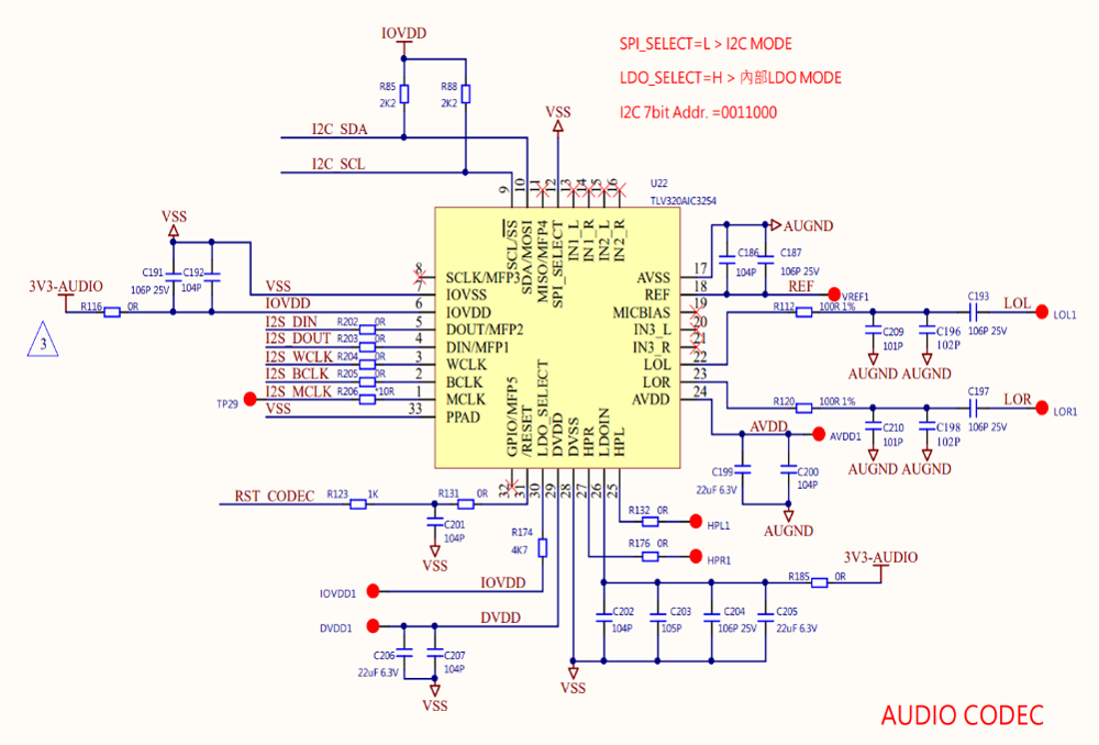
AIC3254.png

AIC3254 stk.png

  • 请注意,本文内容源自机器翻译,可能存在语法或其它翻译错误,仅供参考。如需获取准确内容,请参阅链接中的英语原文或自行翻译。

    您好、

    这是在 LOL/LOR 测试点进行的吗? 您能尝试不使用交流耦合电容器吗? 在低频下、THD 越高、看起来像是信号路径中的电容器。 您可以尝试在编解码器的引脚而不是测试点进行测量、或者取下盖子并在引脚侧进行测量。

    还有一点、中的“规格“在哪里、我在数据表中没有看到? 也许它没有为我正确搜索。  

    此致、
    Mir

  • 请注意,本文内容源自机器翻译,可能存在语法或其它翻译错误,仅供参考。如需获取准确内容,请参阅链接中的英语原文或自行翻译。

    您好、

    这是在 LOL/LOR 测试点进行的吗? 您能尝试不使用交流耦合电容器吗? 在低频下、THD 越高、看起来像是信号路径中的电容器。 您可以尝试在编解码器的引脚而不是测试点进行测量、或者取下盖子并在引脚侧进行测量。

    还有一点、中的“规格“在哪里、我在数据表中没有看到? 也许它没有为我正确搜索。  

    此致、
    Mir

  • 请注意,本文内容源自机器翻译,可能存在语法或其它翻译错误,仅供参考。如需获取准确内容,请参阅链接中的英语原文或自行翻译。

    您好、Jeffres、

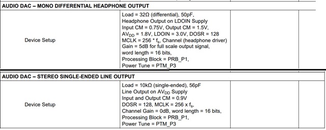
    数据表屏幕截图如下所示:

  • 请注意,本文内容源自机器翻译,可能存在语法或其它翻译错误,仅供参考。如需获取准确内容,请参阅链接中的英语原文或自行翻译。

    您好、

    好的、我看到了。 AIC3254-Q1 数据表中未包含该参数。  

    仔细查看您的图、我看到您的规格约为 30dB。 在我进行自我测试时、我意识到给定的 THD 曲线 适用于差分线路输出、这不是器件的典型用例。 默认的“线路输出“脚本是立体声单端脚本、这意味着您将 LOL 引用到 GND、将 LOR 引用到 GND。 在这种情况下、THD + N 加重~6dB、每通道约–85dB。  

    有助于进行 THD + N 测量的一些事项是确保在 20kHz 时进行滤波并对结果进行 A 加权。

    另一件事 — 您正在运行什么脚本? 您能否发送寄存器配置、以便我可以验证或查看可以更改的内容以帮助提高噪声性能。

    此致、
    Mir

  • 请注意,本文内容源自机器翻译,可能存在语法或其它翻译错误,仅供参考。如需获取准确内容,请参阅链接中的英语原文或自行翻译。

    您好、Jeffres、

    我需要对以下两种模型进行 SDK 寄存器设置进行验证:首先连接平衡线路以验证 IC、

    然后连接非平衡线路以验证系统。

  • 请注意,本文内容源自机器翻译,可能存在语法或其它翻译错误,仅供参考。如需获取准确内容,请参阅链接中的英语原文或自行翻译。

    您好、

    应用参考指南中提供了寄存器设置和寄存器映射示例: https://www.ti.com/lit/an/slaa408a/slaa408a.pdf

    我将使用“48ksps 采样率和高性能的立体声 DAC 回放“示例来构建脚本。

    以下是具有指定更改的耳机输出示例脚本:

    # !headphone output on ldoin supply
    # !cm = 0.75V input , or 1.5v on output
    # !avdd=1.8v, ldoin=3.v, dosr128
    # !gain =5db
    # !16 bit
    # !prb_p1, ptm_p3
    
    # Initialize to Page 0
    w 30 00 00
    # Initialize the device through software reset
    w 30 01 01
    # Power up the NDAC divider with value 1
    w 30 0b 81
    # Power up the MDAC divider with value 2
    w 30 0c 82
    # Program the OSR of DAC to 128
    w 30 0d 00
    w 30 0e 80
    
    w 30 1b 00 #16 bit, i2s
    
    w 30 3c 01 # Set the DAC Mode to PRB_P1
    
    # Select Page 1
    w 30 00 01
    # Disable Internal Crude AVdd in presence of external AVdd supply or before
    #powering up internal AVdd LDO
    w 30 01 08
    # Enable Master Analog Power Control
    w 30 02 00
    # Set the REF charging time to 40ms
    w 30 7b 01
    # HP soft stepping settings for optimal pop performance at power up
    # Rpop used is 6k with N = 6 and soft step = 20usec. This should work with 47uF coupling
    # capacitor. Can try N=5,6 or 7 time constants as well. Trade-off delay vs “pop” sound.
    w 30 14 25
    ## Input Common Mode
    # w 30 0a 00
    w 30 0a 6b #0110 1011 full chip cm=.75, output cm for hp=1.5V, hp powered with LDOIN supply, LDOIN is 3.3V
    
    
    # Route Left DAC to HPL
    w 30 0c 08
    # Route Right DAC to HPR
    w 30 0d 08
    # Set the DAC PTM mode to PTM_P3/4
    w 30 03 00
    w 30 04 00
    
    w 30 10 05 # set HPL gain to 5dB
    w 30 11 05 # set HPR gain to 5dB
    
    # Power up HPL and HPR drivers
    w 30 09 30
    # Wait for 2.5 sec for soft stepping to take effect
    # Else read Page 1, Register 63d, D(7:6). When = “11” soft-stepping is complete
    # Select Page 0
    w 30 00 00
    # Power up the Left and Right DAC Channels with route the Left Audio digital data to
    # Left Channel DAC and Right Audio digital data to Right Channel DAC
    w 30 3f d6
    # Unmute the DAC digital volume control
    w 30 40 00

    # second example:
    # !10k single ended line output on avdd supply
    # !input and output cm=0.9V
    # !dosr=128, mclk=256fs
    # !gain=0db, wordlength=16bit
    # !prb_p1, ptm_p3
    
    # Initialize to Page 0
    w 30 00 00
    # Initialize the device through software reset
    w 30 01 01
    # Power up the NDAC divider with value 1
    w 30 0b 81
    # Power up the MDAC divider with value 2
    w 30 0c 82
    # Program the OSR of DAC to 128
    w 30 0d 00
    w 30 0e 80
    
    w 30 1b 00 #16 bit, i2s
    
    w 30 3c 01 # Set the DAC Mode to PRB_P1
    
    # Select Page 1
    w 30 00 01
    # Disable Internal Crude AVdd in presence of external AVdd supply or before
    #powering up internal AVdd LDO
    w 30 01 08
    # Enable Master Analog Power Control
    w 30 02 00
    # Set the REF charging time to 40ms
    w 30 7b 01
    # HP soft stepping settings for optimal pop performance at power up
    # Rpop used is 6k with N = 6 and soft step = 20usec. This should work with 47uF coupling
    # capacitor. Can try N=5,6 or 7 time constants as well. Trade-off delay vs “pop” sound.
    w 30 14 25
    ## Input Common Mode
    w 30 0a 00 #full chip cm=0.9V, powered by avdd supply
    
    w 30 0e 08 #left DAC to LOL
    w 30 0f 08 #right DAC to LOR
    
    # Set the DAC PTM mode to PTM_P3/4
    w 30 03 00
    w 30 04 00
    
    w 30 12 00 #LOL driver not muted, gain=0dB
    w 30 13 00 #LOR driver not muted, gain=0db
    
    # Power up LOL and LOR drivers
    w 30 09 0c
    # Wait for 2.5 sec for soft stepping to take effect
    # Else read Page 1, Register 63d, D(7:6). When = “11” soft-stepping is complete
    # Select Page 0
    w 30 00 00
    # Power up the Left and Right DAC Channels with route the Left Audio digital data to
    # Left Channel DAC and Right Audio digital data to Right Channel DAC
    w 30 3f d6
    # Unmute the DAC digital volume control
    w 30 40 00
    

    如果您需要更多帮助、请告诉我。

    此致、
    Mir