This thread has been locked.
If you have a related question, please click the "Ask a related question" button in the top right corner. The newly created question will be automatically linked to this question.
https://e2e.ti.com/support/audio-group/audio/f/audio-forum/844635/pcm1864-adding-to-beaglebone-in-tdm-format
有人能帮我通过 tdm 将 pcm1864连接到 BeagleBone 以获得4通道记录吗? 我是最新的 TI SDK、只能通过 I2S 访问2个通道。
Marcin、
PCM1864默认设置为 I2S。 是否通过写入寄存器11将模式更改为 TDM?
此致、
-Steve Wilson
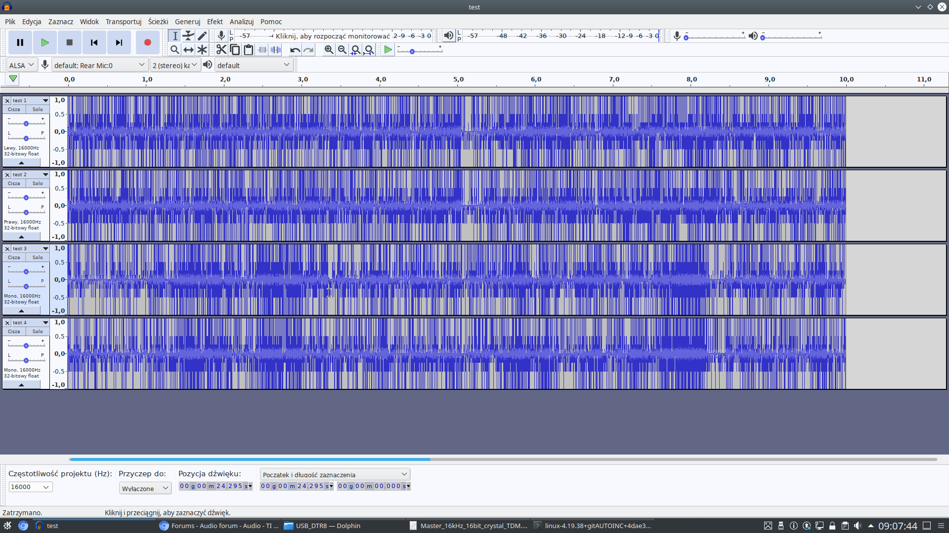
是的、我认为是这样。 您能为我提供 dtsi 和编解码器方面的帮助吗? 我在下面添加了它们、但如果这些文件适用于 tdm 配置、我不会确定它们是否正确。 现在、我能够记录16kHz 4通道、但我只获得一些随机数据。
我的引脚分配:
SCL -> P9 19. SDA -> P9 20 DOUT1A -> P9 41 LRCKA -> P9 27 CKA -> P9 42
以下是我的 i2c 配置:
0x4A 0x0B 0x4F 0x4A 0x0C 0x01 0x4a 0x20 0xB0 0x4a 0x21 0x01 0x4a 0x22 0x01 0x4a 0x23 0x03 0x4A 0x25 0x07 0x4a 0x26 0x02 0x4A 0x27 0xFF 0x4a 0x28 0x01 0x4a 0x29 0x01 0x4a 0x2A 0x00 0x4A 0x2B 0x08
我的 pcm5102a 编解码器:
静态结构 snd_soc_da_driver pcm5102a_dai ={ .name ="pcm5102a-hifi"、 .playback ={ CHANNES_MIN = 2、 .channels_max = 2、 .RAates = SNDRV_PCM_RATE _8000_192000、 .formats = SNDRV_PCM_FMTBIT_S16_LE | SNDRV_PCM_FMTBIT_S24_LE | SNDRV_PCM_FMTBIT_S32_LE }、 .capture ={ .stream_name ="捕捉"、 CHANNES_MIN = 1、 .channels_max = 4、 .RAates = SNDRV_PCM_RATE _8000_192000、 .formats = SNDRV_PCM_FMTBIT_S16_LE | SNDRV_PCM_FMTBIT_S24_LE | SNDRV_PCM_FMTBIT_S32_LE }、 }; 静态结构 snd_soc_component_driver soc_component_dev_pcm5102a ={ IDLE_BIAS_ON = 1、 .use_pmdown_time = 1、 字节序 = 1、 .non_legacy_da_naming = 1、 }; 静态 int pcm5102a_probe (struct platform_device *pdev) { 返回 devm_snd_soc_register_component (&pdev->dev、&osc_component_dev_pcm5102a、 pcm5102a_dai、1); } 静态常量结构 of _device_id pcm5102a_of _match[]={ {.compatible ="ti、pcm5102a"、}、 {} }; MODULE_DEVICE_TABLE (of、pcm5102a_for_match); 静态结构 platform_driver pcm5102a_codec_driver ={ .probe = pcm5102a_probe、 .driver ={ .name ="pcm5102a-codec"、 .of 匹配表= pcm5102a_of 匹配、 }、 }; MODULE_Platform_driver (pcm5102a_codec_driver);
我的额外 dtsi 文件:
am33xx_pinmux{(am33xx_pinmux)} McASP1_PINS:McASP1_PINS{ pinctrl-single、pins =< /*接收器必须启用接收器*/ 0x1a0 0x23 // P9_42 McASP1_aclkx -位时钟*/ 0x1a4 0x23 /* P9_27 McASP1_FSX -帧同步* 0x1a8 0x23 // P9_41 McASP1_axr0 - I2S 输入*/ >; }; }; McASP1{ #sound-di-cells =<0>; pinctrl-names ="default"; pinctrl-0 =<&McASP1_PINs>; 状态="正常"; OP-MODE =<0>;/* MCASP_IIS_MODE */ TDM-SLOTS =<4>; num-serializer =<4>; serial-dir =</* 1 TX 2 RX 0未使用*/ 2 0 1 0 >; Rx-num-evt =<1>; tx-num-evt =<1>; }; /{ pcm5102a:pcm5102a{ #sound-di-cells =<0>; 兼容="ti、pcm5102a"; 状态="正常"; }; Sound1:声音@1{ 兼容="简单音频卡"; simple-audio-card、name ="PCM5102a"; simple-audio-card、format ="DSP_A"; simple-audio-card、bitclock-master =<&sound1_master>; simple-audio-card、frame-master =<&sound1_master>; 简单音频卡、位时钟反转; simple-audio-card、channels-captce-override =<4>; 简单音频卡、CPU{ Sound-Dai =<&McASP1>; }; Sound1_MASTER:简单音频卡、编解码器{ #sound-di-cells =<0>; sound-dai =<&pcm5102a>; 时钟=<&McASP1_Fck>; 时钟名称="MCLK"; }; }; };
向上
0x4a 0x0B 0x4F #将 PCM186x 设置为16位字长、TDM 格式(要求 BCLK = 256 * FS) 0x4a 0x0C 0x01 #将 PCM186x 设置为4通道 TDM 0x4a 0x20 0xB0 # PCM186x 设置为音频总线主控、但 SCLK 设置为 PLL 输出(由 BCLK 生成) 这是不正确的
上面的寄存器应该被配置为0xA1 (从机模式、BLCK 生成的 SCK (PLL 输出)自动配置模式被启用)
或者、如果您希望 PCM1864处于主控模式、 那么它需要来自 XTAL 或 SCLK 的主时钟。 那么、无论您拥有哪一个。
以下寄存 器仅在自动配置模式关闭时需要置位、或仅在器件处于主模式时才需要置位。 但是、在我检查配置之前、我需要您提供有关 SCLK 或 XTAL 频率的更多信息。
我建议您将其设置为自动配置模式、并让 CPU 成为主器件。
0x4a 0x21 0x01 0x4a 0x22 0x01 0x4a 0x23 0x03 0x4A 0x25 0x07 0x4a 0x26 0x02 0x4A 0x27 0xFF 0x4a 0x28 0x01 0x4a 0x29 0x01 0x4a 0x2A 0x00 0x4A 0x2B 0x08