请注意,本文内容源自机器翻译,可能存在语法或其它翻译错误,仅供参考。如需获取准确内容,请参阅链接中的英语原文或自行翻译。
部件号:TMS320F28379D 工具/软件:
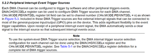
我想收集电压信号并使用 DMA 将其传输到指定的数组。按照例行公事修改后、发现程序无法触发 DMA 的传输中断结束。我尝试在每次 ADC 转换后清除 ADC 的中断标志、DMA 能够正常传输数据并进入结束中断。但是、我在用户手册中看到 DMA 将主动向中断源发出中断清除信号。DMA

我想知道为什么我的程序没有清除 ADC 的中断标志。ADC 的 DMA 传输程序中没有代码清除 ADC 中断、甚至没有启用相应的中断功能、但程序工作正常。这是我的代码、乞求帮助。
#include "driverlib.h"
#include "device.h"
#include "F28x_Project.h"

#define RESULTS_BUFFER_SIZE     256

void initADC(void);
void initEPWM(void);
void initADCSOC(void);
void initializeDMA(void);
void configureDMAChannels(void);

__interrupt void adcA1ISR(void);
__interrupt void dmach1ISR(void);

#pragma DATA_SECTION(adcAResults, "ramgs0");
uint16_t adcAResults[RESULTS_BUFFER_SIZE];
volatile uint16_t bufferFull;

void main(void)
{

    // Initialize device clock and peripherals
    Device_init();

    // Disable pin locks and enable internal pullups.
    Device_initGPIO();

    /*
    #ifdef _STANDALONE
    #ifdef _FLASH
        // Send boot command to allow the CPU2 application to begin execution
        Device_bootCPU2(C1C2_BROM_BOOTMODE_BOOT_FROM_FLASH);
    #else
        // Send boot command to allow the CPU2 application to begin execution
        Device_bootCPU2(C1C2_BROM_BOOTMODE_BOOT_FROM_RAM);
    #endif // _FLASH
    #endif // _STANDALONE
    */

    // Initialize PIE and clear PIE registers. Disables CPU interrupts.
    Interrupt_initModule();

    // Initialize the PIE vector table with pointers to the shell Interrupt
    // Service Routines (ISR).
    Interrupt_initVectorTable();

    // Interrupts that are used in this example are re-mapped to ISR functions
    // found within this file.
    Interrupt_register(INT_ADCA1, &adcA1ISR);

    // ISR for DMA ch1 - occurs when DMA transfer is complete
    Interrupt_register(INT_DMA_CH1, &dmach1ISR);

    // Enable specific PIE & CPU interrupts:
    // DMA interrupt - Group 7, interrupt 1
    Interrupt_enable(INT_DMA_CH1);

    // Set up the ADC and the ePWM and initialize the SOC
    initADC();
    initEPWM();
    initADCSOC();

    // Initialize the DMA & configure DMA channels 1
    initializeDMA();
    configureDMAChannels();

    bufferFull = 0;

    // Enable ADC interrupt
    Interrupt_enable(INT_ADCA1);

    // Clearing all pending interrupt flags
    DMA_clearTriggerFlag(DMA_CH1_BASE);   // DMA channel 1
    HWREGH(ADCA_BASE + ADC_O_INTFLGCLR) = 0x1U; // ADCA

    // Enable Global Interrupt (INTM) and realtime interrupt (DBGM)
    EINT;
    ERTM;

    for(;;)
    {
        // Start DMA
        DMA_startChannel(DMA_CH1_BASE);

        // Start ePWM1, enabling SOCA and putting the counter in up-count mode
        EPWM_enableADCTrigger(EPWM1_BASE, EPWM_SOC_A);
        EPWM_setTimeBaseCounterMode(EPWM1_BASE, EPWM_COUNTER_MODE_UP);

        // Wait while ePWM1 causes ADC conversions which then cause interrupts.
        // When the results buffer is filled, the bufferFull flag will be set.
        while(bufferFull == 0)
        {

        }
        bufferFull = 0;     // Clear the buffer full flag

        // Stop ePWM1, disabling SOCA and freezing the counter
        EPWM_disableADCTrigger(EPWM1_BASE, EPWM_SOC_A);
        EPWM_setTimeBaseCounterMode(EPWM1_BASE, EPWM_COUNTER_MODE_STOP_FREEZE);

        // Software breakpoint. At this point, conversion results are stored in
        // adcAResults.
        // Hit run again to get updated conversions.
        ESTOP0;
    }
}


// Function to configure and power up ADCA.
void initADC(void)
{
    // Set ADCDLK divider to /4
    ADC_setPrescaler(ADCA_BASE, ADC_CLK_DIV_4_0);

    // Set resolution and signal mode (see #defines above) and load
    // corresponding trims.
    ADC_setMode(ADCA_BASE, ADC_RESOLUTION_12BIT, ADC_MODE_SINGLE_ENDED);

    // Set pulse positions to late
    ADC_setInterruptPulseMode(ADCA_BASE, ADC_PULSE_END_OF_CONV);

    // Power up the ADC and then delay for 1 ms
    ADC_enableConverter(ADCA_BASE);
    DEVICE_DELAY_US(1000);
}

// Function to configure ePWM1 to generate the SOC.
void initEPWM(void)
{
    // Disable SOCA
    EPWM_disableADCTrigger(EPWM1_BASE, EPWM_SOC_A);

    // Configure the SOC to occur on the first up-count event
    EPWM_setADCTriggerSource(EPWM1_BASE, EPWM_SOC_A, EPWM_SOC_TBCTR_U_CMPA);
    EPWM_setADCTriggerEventPrescale(EPWM1_BASE, EPWM_SOC_A, 1);

    // Set the compare A value to 1000 and the period to 1999
    // Assuming ePWM clock is 100MHz, this would give 50kHz sampling
    // 50MHz ePWM clock would give 25kHz sampling, etc.
    // The sample rate can also be modulated by changing the ePWM period
    // directly (ensure that the compare A value is less than the period).
    EPWM_setCounterCompareValue(EPWM1_BASE, EPWM_COUNTER_COMPARE_A, 49);
    EPWM_setTimeBasePeriod(EPWM1_BASE, 99);

    // Set the local ePWM module clock divider to /1
    EPWM_setClockPrescaler(EPWM1_BASE,
                           EPWM_CLOCK_DIVIDER_1,
                           EPWM_HSCLOCK_DIVIDER_1);

    // Freeze the counter
    EPWM_setTimeBaseCounterMode(EPWM1_BASE, EPWM_COUNTER_MODE_STOP_FREEZE);
}

// Function to configure ADCA's SOC0 to be triggered by ePWM1.
void initADCSOC(void)
{
    // Configure SOC0 of ADCA to convert pin A1. The EPWM1SOCA signal will be
    // the trigger.
    // - For 12-bit resolution, a sampling window of 15 (75 ns at a 200MHz
    //   SYSCLK rate) will be used.
    // - NOTE: A longer sampling window will be required if the ADC driving
    //   source is less than ideal (an ideal source would be a high bandwidth
    //   op-amp with a small series resistance). See TI application report
    //   SPRACT6 for guidance on ADC driver design.
    ADC_setupSOC(ADCA_BASE, ADC_SOC_NUMBER0, ADC_TRIGGER_EPWM1_SOCA,
                 ADC_CH_ADCIN0, 15);

    // Set SOC0 to set the interrupt 1 flag. Enable the interrupt and make
    // sure its flag is cleared.
    ADC_setInterruptSource(ADCA_BASE, ADC_INT_NUMBER1, ADC_SOC_NUMBER0);
    ADC_enableInterrupt(ADCA_BASE, ADC_INT_NUMBER1);
    ADC_clearInterruptStatus(ADCA_BASE, ADC_INT_NUMBER1);
}

void initializeDMA(void)
{
    // Perform a hard reset on DMA
    DMA_initController();

    // Allow DMA to run free on emulation suspend
    DMA_setEmulationMode(DMA_EMULATION_FREE_RUN);
}

void configureDMAChannels(void)
{
    // DMA channel 1 set up for ADCA
    DMA_configAddresses(DMA_CH1_BASE, (uint16_t *)&adcAResults,
                        (uint16_t *)(ADCARESULT_BASE+ADC_SOC_NUMBER0));

    DMA_configBurst(DMA_CH1_BASE, 1, 0, 0);
    DMA_configTransfer(DMA_CH1_BASE, RESULTS_BUFFER_SIZE, 0, 1);
    DMA_configMode(DMA_CH1_BASE, DMA_TRIGGER_ADCA1,
                  (DMA_CFG_ONESHOT_DISABLE | DMA_CFG_CONTINUOUS_DISABLE |
                   DMA_CFG_SIZE_16BIT));

    DMA_enableTrigger(DMA_CH1_BASE);
    DMA_disableOverrunInterrupt(DMA_CH1_BASE);
    DMA_setInterruptMode(DMA_CH1_BASE, DMA_INT_AT_END);
    DMA_enableInterrupt(DMA_CH1_BASE);
}

// ADC A Interrupt 1 ISR
__interrupt void adcA1ISR(void)
{
    // Add the latest result to the buffer
    //adcAResults[index++] = ADC_readResult(ADCARESULT_BASE, ADC_SOC_NUMBER0);

    // Clear the interrupt flag
    ADC_clearInterruptStatus(ADCA_BASE, ADC_INT_NUMBER1);

    // Check if overflow has occurred
    /*
    if(true == ADC_getInterruptOverflowStatus(ADCA_BASE, ADC_INT_NUMBER1))
    {
        ADC_clearInterruptOverflowStatus(ADCA_BASE, ADC_INT_NUMBER1);
        ADC_clearInterruptStatus(ADCA_BASE, ADC_INT_NUMBER1);
    }
    */

    // Acknowledge the interrupt
    Interrupt_clearACKGroup(INTERRUPT_ACK_GROUP1);

}

#pragma CODE_SECTION(dmach1ISR, ".TI.ramfunc");
__interrupt void dmach1ISR(void)
{
    bufferFull = 1;

    // Acknowledge interrupt
    Interrupt_clearACKGroup(INTERRUPT_ACK_GROUP7);
}
