This thread has been locked.

If you have a related question, please click the "Ask a related question" button in the top right corner. The newly created question will be automatically linked to this question.

[参考译文] TMS320F2.8335万:编程eZdsp TMS320F2.8335万至TMDSSDOCK2.8335万中包含的XDS100v2

Guru**** 2511985 points
Other Parts Discussed in Thread: CCSTUDIO

请注意,本文内容源自机器翻译,可能存在语法或其它翻译错误,仅供参考。如需获取准确内容,请参阅链接中的英语原文或自行翻译。

https://e2e.ti.com/support/microcontrollers/c2000-microcontrollers-group/c2000/f/c2000-microcontrollers-forum/1099934/tms320f28335-programming-ezdsp-tms320f28335-through-xds100v2-included-in-tmdsdock28335

部件号:TMS320F2.8335万
主题中讨论的其他部件: TMDSDOCK2.8335万,CCStudio

您好,

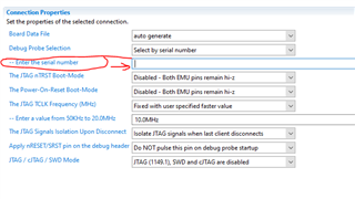
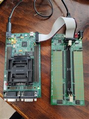
我有两个基于同一DSC的不同开发板,我想知道 应该考虑哪些因素(如果可能) 使用   TMDSDOCK2.8335万坞站基板JTAG接口(具有XDS100v2探头)中包含的编程器对eZdsp TMS320F2.8335万中的处理器进行外部编程。 我连接了两个JTAG插头,并尝试测试连接,该连接表示失败,并显示以下消息:

此错误由TI的USCIF驱动程序或实用程序生成。

值为'-151'(0xffffff69)。
标题为'SC_ERR_FTDI_OPEN。

解释如下:
连接过程中使用的FTDI驱动器功能之一
返回错误状态或错误。 原因可能是一个或
更多信息:没有插入XDS100,XDS100序列号无效,
XDS100 EEPROM空白,FTDI驱动程序缺失,USB电缆故障。
使用'commen/uscif'中的xds100serial命令行实用程序
用于验证XDS100是否可以定位的文件夹。

[结束:Texas Instruments XDS100v2 USB调试探头_0]

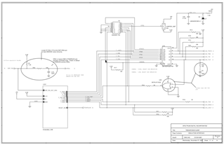
我已经检查了两个主板的示意图,并且一直在整个论坛中搜索,但没有发现任何提及,因此我可能缺少 一些特定的配置。 我希望有人能帮助我。

非常感谢,此致,

克劳斯

  • 请注意,本文内容源自机器翻译,可能存在语法或其它翻译错误,仅供参考。如需获取准确内容,请参阅链接中的英语原文或自行翻译。

    您好,Claus:

    它们是冲突当尝试连接两个XDS100V2时,您需要在CCXML文件中指定与XDS100V2调试器关联的序列号。

    通过Windows命令行,您可以执行xds100serial.exe。

    C:\ti\ccs1040\CCS\CCS_base\con\cuscif\xds100serial.exe

    它将为您提供两个xds100V2仿真器的序列号,您可以在板配置文件(CCXML)中对其进行编程。

    此致,

    Nirav

  • 请注意,本文内容源自机器翻译,可能存在语法或其它翻译错误,仅供参考。如需获取准确内容,请参阅链接中的英语原文或自行翻译。

    我认为我不够清楚,但我没有两个调试探测器,我只有一个,我尝试在eZdsp开发板中对处理器进行编程,但连接测试失败,结果如下:

    [Start: Texas Instruments XDS100v2 USB Debug Probe_0]

    Execute the command:

    %ccs_base%/common/uscif/dbgjtag -f %boarddatafile% -rv -o -F inform,logfile=yes -S pathlength -S integrity

    [Result]


    -----[Print the board config pathname(s)]------------------------------------

    /home/claus/.ti/ccstudio/1/0/BrdDat/testBoard.dat

    -----[Print the reset-command software log-file]-----------------------------

    This utility has selected a 100/110/510 class product.
    This utility will load the adapter 'libjioserdesusb.so'.
    The library build date was 'Mar 17 2022'.
    The library build time was '15:40:16'.
    The library package version is '9.7.0.00213'.
    The library component version is '35.35.0.0'.
    The controller does not use a programmable FPGA.
    The controller has a version number of '4' (0x00000004).
    The controller has an insertion length of '0' (0x00000000).
    This utility will attempt to reset the controller.
    This utility has successfully reset the controller.

    -----[Print the reset-command hardware log-file]-----------------------------

    The scan-path will be reset by toggling the JTAG TRST signal.
    The controller is the FTDI FT2232 with USB interface.
    The link from controller to target is direct (without cable).
    The software is configured for FTDI FT2232 features.
    The controller cannot monitor the value on the EMU[0] pin.
    The controller cannot monitor the value on the EMU[1] pin.
    The controller cannot control the timing on output pins.
    The controller cannot control the timing on input pins.
    The scan-path link-delay has been set to exactly '0' (0x0000).

    -----[The log-file for the JTAG TCLK output generated from the PLL]----------

    There is no hardware for programming the JTAG TCLK frequency.

    -----[Measure the source and frequency of the final JTAG TCLKR input]--------

    There is no hardware for measuring the JTAG TCLK frequency.

    -----[Perform the standard path-length test on the JTAG IR and DR]-----------

    This path-length test uses blocks of 64 32-bit words.

    The test for the JTAG IR instruction path-length failed.
    The JTAG IR instruction scan-path is stuck-at-ones.

    The test for the JTAG DR bypass path-length failed.
    The JTAG DR bypass scan-path is stuck-at-ones.

    -----[Perform the Integrity scan-test on the JTAG IR]------------------------

    This test will use blocks of 64 32-bit words.
    This test will be applied just once.

    Do a test using 0xFFFFFFFF.
    Scan tests: 1, skipped: 0, failed: 0
    Do a test using 0x00000000.
    Test 2 Word 0: scanned out 0x00000000 and scanned in 0xFFFFFFFF.
    Test 2 Word 1: scanned out 0x00000000 and scanned in 0xFFFFFFFF.
    Test 2 Word 2: scanned out 0x00000000 and scanned in 0xFFFFFFFF.
    Test 2 Word 3: scanned out 0x00000000 and scanned in 0xFFFFFFFF.
    Test 2 Word 4: scanned out 0x00000000 and scanned in 0xFFFFFFFF.
    Test 2 Word 5: scanned out 0x00000000 and scanned in 0xFFFFFFFF.
    Test 2 Word 6: scanned out 0x00000000 and scanned in 0xFFFFFFFF.
    Test 2 Word 7: scanned out 0x00000000 and scanned in 0xFFFFFFFF.
    The details of the first 8 errors have been provided.
    The utility will now report only the count of failed tests.
    Scan tests: 2, skipped: 0, failed: 1
    Do a test using 0xFE03E0E2.
    Scan tests: 3, skipped: 0, failed: 2
    Do a test using 0x01FC1F1D.
    Scan tests: 4, skipped: 0, failed: 3
    Do a test using 0x5533CCAA.
    Scan tests: 5, skipped: 0, failed: 4
    Do a test using 0xAACC3355.
    Scan tests: 6, skipped: 0, failed: 5
    Some of the values were corrupted - 83.3 percent.

    The JTAG IR Integrity scan-test has failed.

    -----[Perform the Integrity scan-test on the JTAG DR]------------------------

    This test will use blocks of 64 32-bit words.
    This test will be applied just once.

    Do a test using 0xFFFFFFFF.
    Scan tests: 1, skipped: 0, failed: 0
    Do a test using 0x00000000.
    Test 2 Word 0: scanned out 0x00000000 and scanned in 0xFFFFFFFF.
    Test 2 Word 1: scanned out 0x00000000 and scanned in 0xFFFFFFFF.
    Test 2 Word 2: scanned out 0x00000000 and scanned in 0xFFFFFFFF.
    Test 2 Word 3: scanned out 0x00000000 and scanned in 0xFFFFFFFF.
    Test 2 Word 4: scanned out 0x00000000 and scanned in 0xFFFFFFFF.
    Test 2 Word 5: scanned out 0x00000000 and scanned in 0xFFFFFFFF.
    Test 2 Word 6: scanned out 0x00000000 and scanned in 0xFFFFFFFF.
    Test 2 Word 7: scanned out 0x00000000 and scanned in 0xFFFFFFFF.
    The details of the first 8 errors have been provided.
    The utility will now report only the count of failed tests.
    Scan tests: 2, skipped: 0, failed: 1
    Do a test using 0xFE03E0E2.
    Scan tests: 3, skipped: 0, failed: 2
    Do a test using 0x01FC1F1D.
    Scan tests: 4, skipped: 0, failed: 3
    Do a test using 0x5533CCAA.
    Scan tests: 5, skipped: 0, failed: 4
    Do a test using 0xAACC3355.
    Scan tests: 6, skipped: 0, failed: 5
    Some of the values were corrupted - 83.3 percent.

    The JTAG DR Integrity scan-test has failed.

    [End: Texas Instruments XDS100v2 USB Debug Probe_0]

    我添加一张图片以显示硬件配置:

    为了确保我做得好,我遵循了每块板示意图中的每一条轨迹。 我发现JTAG电缆提供的电压有一些压降,因此移除了eZdsp电路板中的跳线JR2,以便能够通过5V电源为外部供电。

    从 TMDSDOCK2.8335万扩展坞基板 原理图中可以清楚地看出,JTAG连接通过电缆进行倾斜,在eZdsp原理图中,为了清晰起见,我复制了此处的第54页,mux保持配置为可从外部进行编程的主板

    此致,

    克劳斯

  • 请注意,本文内容源自机器翻译,可能存在语法或其它翻译错误,仅供参考。如需获取准确内容,请参阅链接中的英语原文或自行翻译。

    您好,Claus:

    有多种情况会导致您无法正确扫描信号。 请参阅以下材料以找出根本原因。

    一种可能的情况是JTAG信号的端接电阻,您的信号从JTAG插头到DSP的距离有多远?

    请参阅以下材料:

    JTAG指南: http://www.ti.com/lit/an/spracf0/spracf0.pdf  

    TI资源浏览器(XDS): http://dev.ti.com/tirex/explore/node?node=AL8OWQmGKOMEKEatbOtBgg__FUz-xrs__LATEST

    调试JTAG: https://software-dl.ti.com/ccs/esd/documents/ccs_debugging_jtag_connectivity_issues.html#host-connection-error

    https://www.ti.com/lit/ug/spru655i/spru655i.pdf

    此致,

    Nirav