请注意,本文内容源自机器翻译,可能存在语法或其它翻译错误,仅供参考。如需获取准确内容,请参阅链接中的英语原文或自行翻译。
部件号:TMS320F2.8034万 您好,
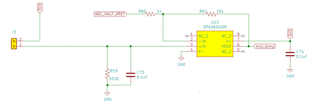
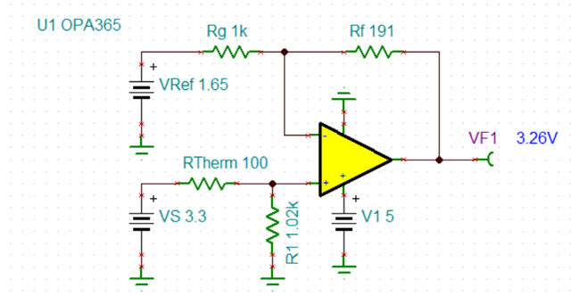
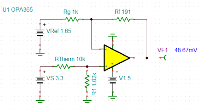
我正在设计一个BLDC驱动单元,并且使用 TMS320F2.8034万PNS作为微控制器。 设计要求之一是能够使用热敏电阻传感器读取BLDC电机绕组的温度。 我需要一些有关调节电路设计的帮助,以便将传感器与微控制器连接起来。 请帮我解决这个问题吗? 是否有应用说明或参考设计可以提供帮助?
谢谢
Giorgio
您好,
我正在设计一个BLDC驱动单元,并且使用 TMS320F2.8034万PNS作为微控制器。 设计要求之一是能够使用热敏电阻传感器读取BLDC电机绕组的温度。 我需要一些有关调节电路设计的帮助,以便将传感器与微控制器连接起来。 请帮我解决这个问题吗? 是否有应用说明或参考设计可以提供帮助?
谢谢
Giorgio