

Other Parts Discussed in Thread: C2000WARE
主题中讨论的其他器件:C2000WARE
您好!
我遇到了软件强制 ADC 转换的问题。 我有两个 ADC 中断。 一个是在 SO0和 SOC1上同步进行 ADC 转换时 EOC 触发的快速中断。 较慢的中断是在 SOC2和 SOC3上同步进行 ADC 转换时 EOC 触发的。 较慢的中断 SOC 从快速中断中的递减采样数中触发。 我注意到代码中有伪中断、似乎是软件强制中断调用的原因;在注释掉软件强制中断调用后、伪快速中断不会发生。 这个问题的另一个因素是我在 PIE 中使用了两个中断。 当我将较慢的中断更改为使用 PIEIER10时、代码工作正常。 请参阅以下代码。 我会发布我的所有代码、但很遗憾它很大。 重要的一点不是直接使用整个寄存器访问、而不是 c2000ware 代码中的逐位示例。 下面是我观察到的内容的屏幕截图
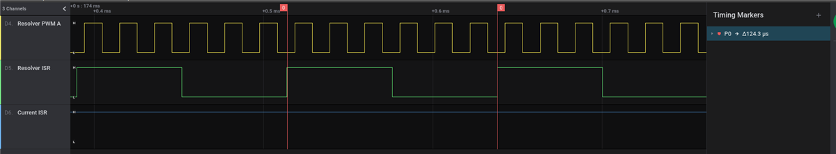
并注释掉软件强制中断
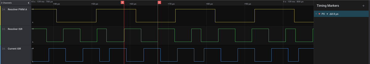
在软件强制中断的情况下、中断保持触发状态
以下 是相关的代码摘录。 我``问题出在快速 ISR 内部的 Δ Σ AdcRegs.ADCSOCFRC1 |= ADCSOC_SOC2;Δ Σ。 我的调试器显示 PIEIFR1和 ADCINTFLG 的中断标志看起来正确、也只有 ADCINT1处于暂挂状态。 然而、在调用软件强制 SoC 后、ADCINTFLG 会转至0x0103、PIEIFR1 = 0x0022、ADCINTOVF = 0x0003。 我已经检查 了 AdcRegs.ADCSOCFRC1的存储器地址、它是正确的。
问题:
- 是否无法从 ISR 上下文中调用软件强制 SoC?
- RMW 操作和 ADCSOCFRC1不正确吗?
- 是否一次无法使用来自 PIE 组的多个中断?
static const PwmConfig resolver_pwm_config =
{
.enable_center_aligned=true,
.counts=937,//94,
.adc_trigger={.enable=true, .event_scaler=ePwmSocPulseOnThirdEvent},
.compliment={.enable=false, .edge_delay=0},
.sync={.enable=false, .phase_counts=0, .sync_out=ePwmSyncOutSyncIn}
};
static const SampleConfig resolver_adc_config =
{
.soc_index=0,
.channel=eAdcInA0,
.trigger_source=eAdcTriggerPwm1SocA,
.sample_time=7,
.enable_simultaneous_sample=true,
.adc_interrupt={.enable=true, .interrupt_index=1}
};
static const SampleConfig current_adc_config =
{
.soc_index=2,
.channel=eAdcInA1,
.trigger_source=eAdcTriggerSoftware,
.sample_time=7,
.enable_simultaneous_sample=true,
.adc_interrupt={.enable=true, .interrupt_index=2}
};
__interrupt void adc_resolver_isr(void)
{
static const unsigned down_count = 4;
static unsigned isr_count = 0;
hal_resolver_isr_pin_toggle();
hal_resolver_sin = AdcResult.ADCRESULT0;
hal_resolver_cos = AdcResult.ADCRESULT1;
// start phase current adc sampling
if (++isr_count >= down_count)
{
isr_count = 0;
AdcRegs.ADCSOCFRC1 |= ADCSOC_SOC2;
}
AdcRegs.ADCINTFLGCLR |= ADCINT_BIT1;
AdcRegs.ADCINTOVFCLR |= ADCINT_BIT1;
PieCtrlRegs.PIEACK = PIEACK_GROUP1;
}
__interrupt void adc_current_isr(void)
{
static unsigned down_count = 20;
static unsigned isr_count = 0;
hal_current_isr_pin_toggle();
hal_current_a = AdcResult.ADCRESULT2;
hal_current_b = AdcResult.ADCRESULT3;
AdcRegs.ADCINTFLGCLR |= ADCINT_BIT2;
AdcRegs.ADCINTOVFCLR |= ADCINT_BIT2;
PieCtrlRegs.PIEACK = PIEACK_GROUP1;
}
void hal_boot_init(void)
{
f28_setup_system_control(&system_config);
DINT; // Disable CPU interrupts
f28_setup_peripheral_interrupt_control();
// Disable CPU interrupts and clear all CPU interrupt flags
IER = 0x0000;
IFR = 0x0000;
f28_setup_peripheral_interrupt_table();
// map isrs
EALLOW;
PieVectTable.ADCINT1 = &adc_resolver_isr;
PieVectTable.ADCINT2 = &adc_current_isr;
PieVectTable.ADCINT9 = &adc_1kHz_isr;
PieVectTable.TINT2 = &cpu_timer2_isr;
PieVectTable.SPIRXINTA = &sci_rxa_isr;
EDIS;
hal_gpio_init();
f28_adc_init();
f28_adc_soc_setup(&adc_1khz_config);
f28_adc_soc_setup(¤t_adc_config);
f28_adc_soc_setup(&resolver_adc_config);
f28_timer_init(&CpuTimer2Regs, &msec_timer_config);
f28_sci_init(&SciaRegs, &sci_a_config, LSPCLK_SPEED);
f28_can_init(&can_node, &can_bitrate, &can_mask_filter);
f28_pwm_init(&EPwm1Regs, &resolver_pwm_config);
// Enable ADCINT1,2,9
PieCtrlRegs.PIEIER1 = (PIEIxR_INTx1 | PIEIxR_INTx2 | PIEIxR_INTx6);
// Enable SCIRXA
PieCtrlRegs.PIEIER9 = (PIEIxR_INTx1);
// Enable Int1=Adc; Int9=sci; Int14=timer2 interrupt
IER = (IxR_INT1 | IxR_INT9 | IxR_INT14);
// Enable global Interrupts and higher priority real-time debug events
EINT; // Enable Global interrupt INTM
ERTM; // Enable Global realtime interrupt DBGM
}
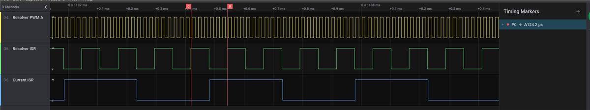
最后、这里是使用 ADCINT3和 PIEIER10的跟踪。 这就是我期望发生的情况。 代码更改如下;该代码不会在软件 SoC 启动后产生奇数 ADCINTFLG = 0x0103。 但是、它会产生 ADCINTFLG = 0x0005、PIEIF1 = 0x0002、PIEIF10 = 0x0007、ADCINTOVF = 0x0000。 这里奇怪的是、为什么 ADCINTFLG = 0x0005而不是0x0001?
static const SampleConfig current_adc_config =
{
.soc_index=2,
.channel=eAdcInA1,
.trigger_source=eAdcTriggerSoftware,
.sample_time=7,
.enable_simultaneous_sample=true,
.adc_interrupt={.enable=true, .interrupt_index=3}
};
__interrupt void adc_current_isr(void)
{
static unsigned down_count = 20;
static unsigned isr_count = 0;
hal_current_isr_pin_toggle();
hal_current_a = AdcResult.ADCRESULT2;
hal_current_b = AdcResult.ADCRESULT3;
AdcRegs.ADCINTFLGCLR |= ADCINT_BIT3;
AdcRegs.ADCINTOVFCLR |= ADCINT_BIT3;
PieCtrlRegs.PIEACK = PIEACK_GROUP10;
}
void hal_boot_init(void)
{
f28_setup_system_control(&system_config);
DINT; // Disable CPU interrupts
f28_setup_peripheral_interrupt_control();
// Disable CPU interrupts and clear all CPU interrupt flags
IER = 0x0000;
IFR = 0x0000;
f28_setup_peripheral_interrupt_table();
// map isrs
EALLOW;
PieVectTable.ADCINT1 = &adc_resolver_isr;
PieVectTable.ADCINT3 = &adc_current_isr;
PieVectTable.ADCINT9 = &adc_1kHz_isr;
PieVectTable.TINT2 = &cpu_timer2_isr;
PieVectTable.SPIRXINTA = &sci_rxa_isr;
EDIS;
hal_gpio_init();
f28_adc_init();
f28_adc_soc_setup(&adc_1khz_config);
f28_adc_soc_setup(¤t_adc_config);
f28_adc_soc_setup(&resolver_adc_config);
f28_timer_init(&CpuTimer2Regs, &msec_timer_config);
f28_sci_init(&SciaRegs, &sci_a_config, LSPCLK_SPEED);
f28_can_init(&can_node, &can_bitrate, &can_mask_filter);
f28_pwm_init(&EPwm1Regs, &resolver_pwm_config);
// Enable ADCINT1,2,9
PieCtrlRegs.PIEIER1 = (PIEIxR_INTx1 | PIEIxR_INTx6);
PieCtrlRegs.PIEIER10 = PIEIxR_INTx3;
// Enable SCIRXA
PieCtrlRegs.PIEIER9 = (PIEIxR_INTx1);
// Enable Int1=Adc; Int9=sci; Int14=timer2 interrupt
IER = (IxR_INT1 | IxR_INT9 | IxR_INT10 | IxR_INT14);
// Enable global Interrupts and higher priority real-time debug events
EINT; // Enable Global interrupt INTM
ERTM; // Enable Global realtime interrupt DBGM
}
