

请注意,本文内容源自机器翻译,可能存在语法或其它翻译错误,仅供参考。如需获取准确内容,请参阅链接中的英语原文或自行翻译。
器件型号:LAUNCHXL-F28379D 主题中讨论的其他器件:C2000WARE
您好!
我正在将 SPI 编码 器(IC-Haus MU150)集成到 LaunchPAD-F28379D 中
我下载了 C2000Ware 并修改了 SPI 示例项目3 "spi_ex3_external_loopback _fifo_interrupts.c"
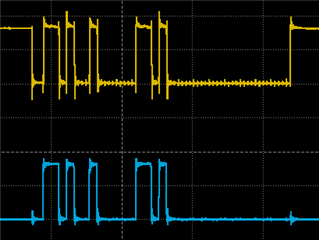
在调试控制台和示波器测量中、我看到编码 器 SOMI (黄色)在 SIMO 线路中回显、并且不会发回任何有用的数据
此外、SPISTEB 引脚似乎保持下拉状态而不产生任何信号。
这是我使用的代码
#include "driverlib.h"
#include "device.h"

/* MU150 masks */
#define MU150_OP_SDAD 0xA6
#define MU150_OP_REG_STATUS_DATA 0xAD
#define MU150_OP_WRITE_REG 0xD2
#define MU150_STATUS_VALID 0x01
#define MU150_SDAD_VALID 0x00
#define MU150_OP_READ_REG 0x97
#define MU150_ADDR_ACC_STAT 0x0D
#define MU150_ACC_STAT_BIT (0x01 << 7U)
#define MU150_ADDR_STATUS0 0x76
#define MU150_AM_MIN_BIT (0x01 << 0U)
#define MU150_AM_MAX_BIT (0x01 << 1U)
#define MU150_AN_MIN_BIT (0x01 << 2U)
#define MU150_AN_MAX_BIT (0x01 << 3U)
#define MU150_NON_CTR_BIT (0x01 << 3U)
#define MU150_EPR_ERR (0x01 << 6U)
#define MU150_ADDR_STATUS1 0x77
#define SPI_PACKET_SIZE (4U)
#define MU150_ADDR_FILT 0x0e
#define MU150_FILT1 0x01
#define MU150_FILT3 0x03 // 27dB
#define MU150_FILT4 0x04 // 39dB
#define MU150_FILT5 0x05 // 45dB


//
// Globals
//
volatile uint16_t sData[4];         // Send data buffer
volatile uint16_t rData[4];         // Receive data buffer
volatile uint16_t rDataPoint = 0;   // To keep track of where we are in the
volatile uint16_t exe_rx = 0;
volatile uint16_t exe_tx = 0;  // data stream to check received data

//
// Function Prototypes
//
void initSPIBMaster(void);
void initSPIASlave(void);
void configGPIOs(void);
__interrupt void spibTxFIFOISR(void);
__interrupt void spibRxFIFOISR(void);

//
// Main
//
void main(void)
{
    uint16_t i;

    //
    // Initialize device clock and peripherals
    //
    Device_init();

    //
    // Disable pin locks and enable internal pullups.
    //
    Device_initGPIO();

    //
    // Initialize PIE and clear PIE registers. Disables CPU interrupts.
    //
    Interrupt_initModule();

    //
    // Initialize the PIE vector table with pointers to the shell Interrupt
    // Service Routines (ISR).
    //
    Interrupt_initVectorTable();

    //
    // Interrupts that are used in this example are re-mapped to ISR functions
    // found within this file.
    //
    Interrupt_register(INT_SPIB_TX, &spibTxFIFOISR);
    Interrupt_register(INT_SPIB_RX, &spibRxFIFOISR);

    //
    // Configure GPIOs for external loopback.
    //
    configGPIOs();

    //
    // Set up SPI B as master, initializing it for FIFO mode
    //
    initSPIBMaster();

    //
    // Set up SPI A as slave, initializing it for FIFO mode
    //
    //initSPIASlave();

    //
    // Initialize the data buffers
    //
    //sData[0] = MU150_OP_WRITE_REG;
   // sData[1] = MU150_ADDR_ACC_STAT;
   // sData[2] = MU150_ACC_STAT_BIT;
    sData[0] = MU150_OP_WRITE_REG;
    sData[1] = MU150_ADDR_ACC_STAT;
    sData[2] = MU150_ACC_STAT_BIT;
    sData[3] = 0;

    rData[0]=0;
    rData[1]=0;
    rData[2]=0;
    rData[3]=0;

    //
    // Enable interrupts required for this example
    //

    Interrupt_enable(INT_SPIB_TX);
    Interrupt_enable(INT_SPIB_RX);


    //
    // Enable Global Interrupt (INTM) and realtime interrupt (DBGM)
    //
    EINT;
    ERTM;
    sData[0] = 0xA6;
    sData[1] = 0;
    sData[2] = 0;
    sData[3] = 0;
    //
    // Loop forever. Suspend or place breakpoints to observe the buffers.
    //
    while(1)
    {

        ;


    }
}

//
// Function to configure SPI B as master with FIFO enabled.
//
void initSPIBMaster(void)
{
    //
    // Must put SPI into reset before configuring it
    //
    SPI_disableModule(SPIB_BASE);

    //
    // SPI configuration. Use a 500kHz SPICLK and 16-bit word size.
    //
    SPI_setConfig(SPIB_BASE, DEVICE_LSPCLK_FREQ, SPI_PROT_POL0PHA0,
                  SPI_MODE_MASTER, 500000, 32);
    SPI_disableLoopback(SPIB_BASE);
    SPI_setEmulationMode(SPIB_BASE, SPI_EMULATION_FREE_RUN);

    //
    // FIFO and interrupt configuration
    //
    SPI_enableFIFO(SPIB_BASE);
    SPI_clearInterruptStatus(SPIB_BASE, SPI_INT_TXFF);
    SPI_clearInterruptStatus(SPIB_BASE, SPI_INT_RXFF);
    SPI_setFIFOInterruptLevel(SPIB_BASE, SPI_FIFO_TX1, SPI_FIFO_RX1);
    SPI_enableInterrupt(SPIB_BASE, SPI_INT_TXFF);
    SPI_enableInterrupt(SPIB_BASE, SPI_INT_RXFF);
    //
    // Configuration complete. Enable the module.
    //
    SPI_enableModule(SPIB_BASE);
}


//
// Configure GPIOs for external loopback.
//
void configGPIOs(void)
{
    //
    // This test is designed for an external loopback between SPIA
    // and SPIB.
    // External Connections:
    // -GPIO25 and GPIO17 - SPISOMI
    // -GPIO24 and GPIO16 - SPISIMO
    // -GPIO27 and GPIO19 - SPISTE
    // -GPIO26 and GPIO18 - SPICLK
    //

    //
    // GPIO17 is the SPISOMIA.
    //


    //
    // GPIO25 is the SPISOMIB.
    //
    GPIO_setMasterCore(64, GPIO_CORE_CPU1);
    GPIO_setPinConfig(GPIO_64_SPISOMIB);
    GPIO_setPadConfig(64, GPIO_PIN_TYPE_PULLUP);
    GPIO_setQualificationMode(64, GPIO_QUAL_ASYNC);

    //
    // GPIO24 is the SPISIMOB clock pin.
    //
    GPIO_setMasterCore(63, GPIO_CORE_CPU1);
    GPIO_setPinConfig(GPIO_63_SPISIMOB);
    GPIO_setPadConfig(63, GPIO_PIN_TYPE_PULLUP);
    GPIO_setQualificationMode(63, GPIO_QUAL_ASYNC);

    //
    // GPIO27 is the SPISTEB.
    //
    GPIO_setMasterCore(66, GPIO_CORE_CPU1);
    GPIO_setPinConfig(GPIO_66_SPISTEB);
    GPIO_setPadConfig(66, GPIO_PIN_TYPE_PULLUP);
    GPIO_setQualificationMode(66, GPIO_QUAL_ASYNC);

    //
    // GPIO26 is the SPICLKB.
    //
    GPIO_setMasterCore(65, GPIO_CORE_CPU1);
    GPIO_setPinConfig(GPIO_65_SPICLKB);
    GPIO_setPadConfig(65, GPIO_PIN_TYPE_PULLUP);
    GPIO_setQualificationMode(65, GPIO_QUAL_ASYNC);
}

//
// SPI A Transmit FIFO ISR
//
__interrupt void spibTxFIFOISR(void)
{
    uint16_t i;

    //
    // Send data
    //
    for(i = 0; i < 4; i++)
    {
       SPI_writeDataNonBlocking(SPIB_BASE, sData[i]);
    }
    //exe_tx++;

    //
    // Increment data for next cycle
    //


    //
    // Clear interrupt flag and issue ACK
    //
    SPI_clearInterruptStatus(SPIB_BASE, SPI_INT_TXFF);
    Interrupt_clearACKGroup(INTERRUPT_ACK_GROUP6);
}

//
// SPI B Receive FIFO ISR
//
 __interrupt void spibRxFIFOISR(void)
{
    uint16_t i;

    //
    // Read data
    //
    for(i = 0; i < 4; i++)
    {
        rData[i] = SPI_readDataNonBlocking(SPIB_BASE);
    }
    //exe_rx++;
    //
    // Check received data
    //


    //
    // Clear interrupt flag and issue ACK
    //
    SPI_clearInterruptStatus(SPIB_BASE, SPI_INT_RXFF);
    Interrupt_clearACKGroup(INTERRUPT_ACK_GROUP6);

}

//
// End of File
//
有人可以帮助我发现这方面的错误吗? 使用中断可能会产生错误的逻辑流程?
谢谢
Hansol
