请注意,本文内容源自机器翻译,可能存在语法或其它翻译错误,仅供参考。如需获取准确内容,请参阅链接中的英语原文或自行翻译。
器件型号:LAUNCHXL-F280049C InstantinFOC SDK V2.01:
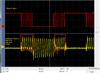
将 ePWM 模块 CMPB 配置为比较加载/直接加载到周期寄存器中的 DN 计数无法将任何值加载到任何已配置发生器的 CMPB 中。
由于 typedef 枚举缺失 epwm.h 或 HW_EPWM.h、因此无法通过 DBCTL[POLSEL]为模式2 ACK/ACL 互补型配置死区发生器(图18-8)
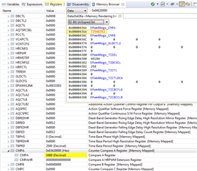
注意:我尝试在下面添加枚举、但极性位 S2、S3分别为2、3时导致加载馈送模式寄存器位发生变化。 寄存器控制函数调用中存在重叠、因此将(模式/极性)寄存器加载分离为两个函数不会引起混淆。 互补死区模式2的移位/掩码枚举值与模式4不同、因此旧版 C2000固件函数调用无法正常工作、因为它用于模式2死区控制。 从下面的调用中可以设置最近的 DBCTL 寄存器(0x000A)。
//*****************************************************************************
//
//! Values that can be passed to EPWM_setDeadBandDelayPolarity(),
//! EPWM_setDeadBandDelayMode() as the \e delayMode parameter.
//
//*****************************************************************************
typedef enum
{
    EPWM_DB_RED = 1, //!< DB RED (Rising Edge Delay) mode
    EPWM_DB_FED = 0, //!< DB FED (Falling Edge Delay) mode
	EPWM_DB_AHC = 1, //!< DB mode AH is Complementary
	EPWM_DB_ALC = 0  //!< DB mode AL is Complementary
} EPWM_DeadBandDelayMode;

//*****************************************************************************
//
//! Values that can be passed to EPWM_setDeadBandDelayPolarity as the
//! \e polarity parameter.
//
//*****************************************************************************
typedef enum
{
    EPWM_DB_POLARITY_ACTIVE_HIGH = 0, //!< DB polarity is not inverted
    EPWM_DB_POLARITY_ACTIVE_LOW  = 1,  //!< DB polarity is inverted
	EPWM_DB_POLARITY_ACTIVE_HIGH_COMPLMNT = 2, //!< DB polarity is High Complementary
	EPWM_DB_POLARITY_ACTIVE_LOW_COMPLMNT = 1 //!< DB polarity is Low Complementary

} EPWM_DeadBandPolarity;
1、当 TRM 中显示 Instaspin SVM 模块代码并声明该代码供设计人员检查时、为什么要将其嵌入 ROM 中?
2.为什么在 ROM 中的 SVM 模块没有通过下面给定的代码加载 CMPB 寄存器的任何计数值?
如何在不配置相对于 SDK InstaSPIN FOC 的死区模式2的情况下通过 ROM 或固件配置对称互补(ePWM-A/B 驱动信号)?
4.为什么使用 C2000寄存器枚举值(epwm.h 等) 与 TRM 图和寄存器布局相关的二进制/十六进制值不一致? 相反、C2000固件开发使设计人员无法在不进入 CCS 调试寄存器视图的情况下使用 TRM 快速查看。
        // setup the Counter-Compare Control Register (CMPCTL)
        EPWM_setCounterCompareShadowLoadMode(obj->pwmHandle[cnt],
                                             EPWM_COUNTER_COMPARE_B,
                                             EPWM_COMP_LOAD_ON_CNTR_ZERO);

        // setup the Action-Qualifier Output B Register (AQCTLB)
        EPWM_setActionQualifierAction(obj->pwmHandle[cnt],
                                      EPWM_AQ_OUTPUT_B,
                                      EPWM_AQ_OUTPUT_HIGH,
                                      EPWM_AQ_OUTPUT_ON_TIMEBASE_UP_CMPB);
		//
        EPWM_setActionQualifierAction(obj->pwmHandle[cnt],
                                      EPWM_AQ_OUTPUT_B,
                                      EPWM_AQ_OUTPUT_LOW,
                                      EPWM_AQ_OUTPUT_ON_TIMEBASE_DOWN_CMPB);

                                             // setup the Dead-Band Generator load mode Register (DBCTL)
        EPWM_setDeadBandDelayMode(obj->pwmHandle[cnt], EPWM_DB_AHC_RED, true); //EPWM_DB_RED
        EPWM_setDeadBandDelayMode(obj->pwmHandle[cnt], EPWM_DB_AHC_FED, true);

        // select EPWMA as the input to the dead band generator
        EPWM_setRisingEdgeDeadBandDelayInput(obj->pwmHandle[cnt],
                                             EPWM_DB_INPUT_EPWMA);

        // setup DBCTRL mode/polarity for H/L symmetric complementary dead band.
        EPWM_setDeadBandDelayPolarity(obj->pwmHandle[cnt],
                                      EPWM_DB_AHC,
                                      EPWM_DB_POLARITY_ACTIVE_HIGH_COMPLMNT);

        // setup the Dead-Band Rising Edge Delay Register (DBRED)
        EPWM_setRisingEdgeDelayCount(obj->pwmHandle[cnt], HAL_PWM_DBRED_CNT);

        // setup the Dead-Band Falling Edge Delay Register (DBFED)
        EPWM_setFallingEdgeDelayCount(obj->pwmHandle[cnt], HAL_PWM_DBFED_CNT);