This thread has been locked.
If you have a related question, please click the "Ask a related question" button in the top right corner. The newly created question will be automatically linked to this question.
尊敬的社区成员:
我不熟悉 PID 控制器仿真。 我检查了数字控制库(DCL)。 我想对简单的 PID 块进行仿真。 构建文件时出现一些错误。 请提供建议。
我遵循的步骤如下所示:
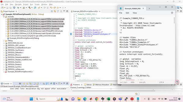
首先、我选择 "示例_F28069_pid.c" 来自 DCL 库(C:\ti\c2000\C2000Ware_4_03_00_00\libraries\control\DCL\c28\examples\F28069_PID)。
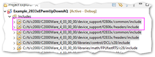
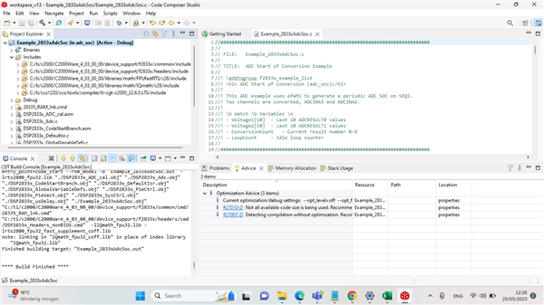
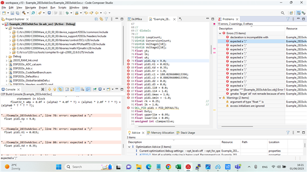
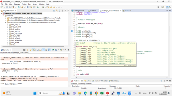
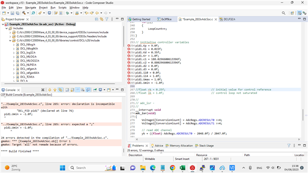
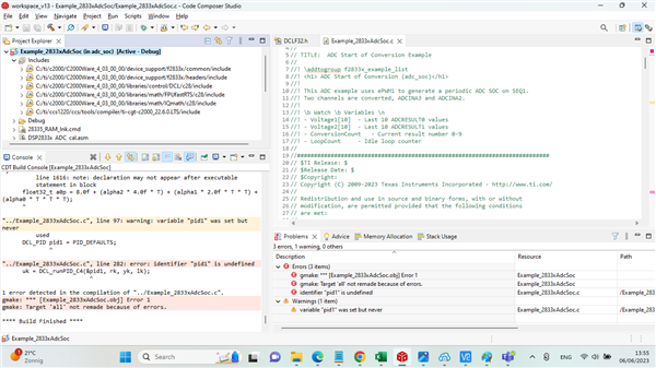
2-然后我上传了 CCS 程序并将头文件从 F2806x 更改为 DSPf2833x (第9-11行)、因为我使用的是 F28335器件(带有评估板的控制卡)。 您还可以在"Project Explorer"部分中看到包含的文件。 请参见下图。
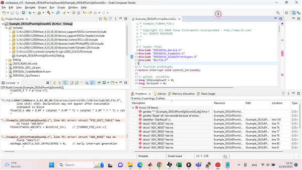
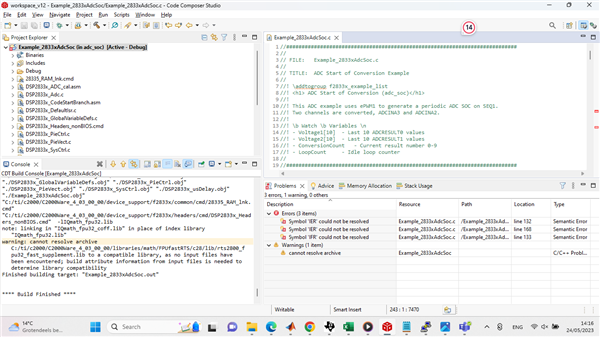
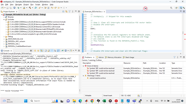
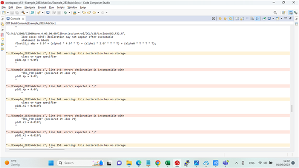
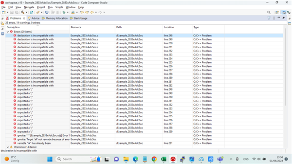
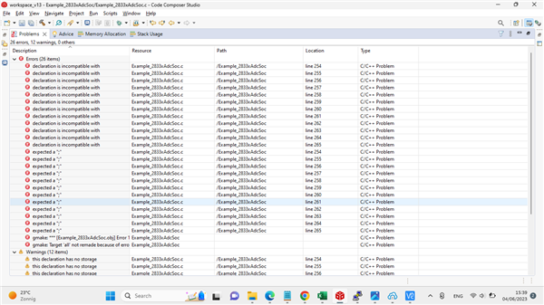
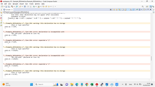
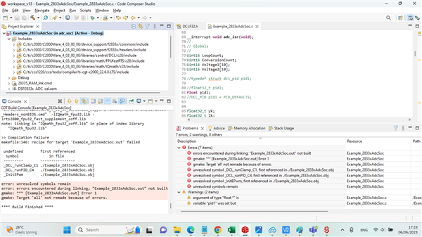
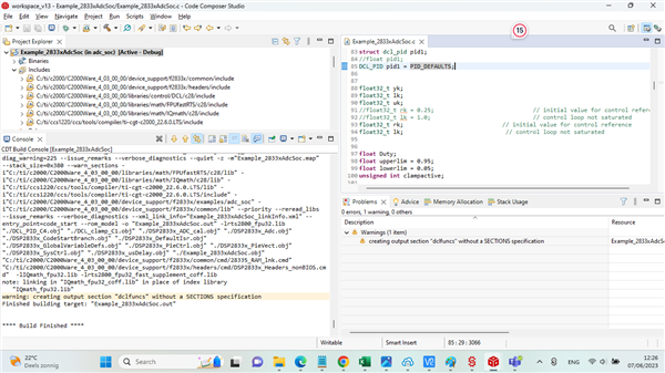
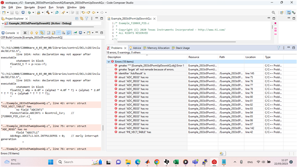
3-在编译工程时、控制台窗口中出现18个错误。 请参阅随附的 错误文件和问题窗口图片:
e2e.ti.com/.../console_5F00_err.txt
4-代码附在此处:
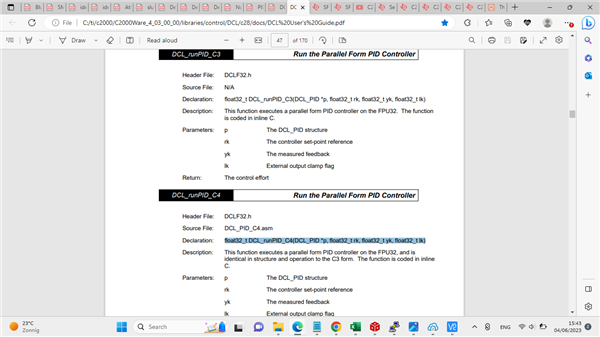
/* Example_F28069_PID.c * * Copyright (C) 2020 Texas Instruments Incorporated - http://www.ti.com/ * ALL RIGHTS RESERVED * */ // header files #include "DSP2833x_Device.h" #include "DSP2833x_Examples.h" #include "DSP2833x_GlobalPrototypes.h" #include "DCLF32.h" // function prototypes extern interrupt void control_Isr(void); // global variables long IdleLoopCount = 0; long IsrCount = 0; float rk = 0.25f; float yk; float lk; float uk; DCL_PID pid1 = PID_DEFAULTS; float Duty; float upperlim = 0.95f; float lowerlim = 0.05f; unsigned int clampactive; /* main */ main() { /* initialise system */ InitSysCtrl(); // [F2806x_SysCtrl.c] DINT; // disable interrupts IER = 0x0000; IFR = 0x0000; InitPieCtrl(); // initialise PIE control registers [F2806x_PieCtrl.c] InitPieVectTable(); // initialise PIE vector table [F2806x_PieVect.c] EALLOW; PieVectTable.ADCINT1 = &control_Isr; // [F28069_PID_cisr.c] EDIS; /* configure ePWM1 */ EALLOW; SysCtrlRegs.PCLKCR0.bit.TBCLKSYNC = 0; EDIS; InitEPwm(); // [F2806x_EPwm.c] EPwm1Regs.TBCTL.bit.CTRMODE = 3; // freeze TB counter EPwm1Regs.TBCTL.bit.PRDLD = 1; // immediate load EPwm1Regs.TBCTL.bit.PHSEN = 0; // disable phase loading EPwm1Regs.TBCTL.bit.SYNCOSEL = 3; // disable SYNCOUT signal EPwm1Regs.TBCTL.bit.HSPCLKDIV = 0; // TBCLK = SYSCLKOUT EPwm1Regs.TBCTL.bit.CLKDIV = 0; // clock divider = /1 EPwm1Regs.TBCTL.bit.FREE_SOFT = 2; // free run on emulation suspend EPwm1Regs.TBPRD = 0x2328; // set period for ePWM1 (0x2328 = 10kHz) EPwm1Regs.TBPHS.all = 0; // time-base Phase Register EPwm1Regs.TBCTR = 0; // time-base Counter Register EPwm1Regs.ETSEL.bit.SOCAEN = 1; // enable SOC on A group EPwm1Regs.ETSEL.bit.SOCASEL = 1; // select SOC from zero match EPwm1Regs.ETPS.bit.SOCAPRD = 1; // generate pulse on 1st event EPwm1Regs.CMPCTL.bit.SHDWAMODE = 0; // enable shadow mode EPwm1Regs.CMPCTL.bit.LOADAMODE = 2; // reload on CTR=zero EPwm1Regs.CMPA.half.CMPA = 0x0080; // set compare A value EPwm1Regs.AQCTLA.bit.CAU = AQ_SET; // HIGH on CMPA up match EPwm1Regs.AQCTLA.bit.ZRO = AQ_CLEAR; // LOW on zero match EALLOW; SysCtrlRegs.PCLKCR0.bit.TBCLKSYNC = 1; EDIS; /* configure ADC */ InitAdc(); // [F2806x_Adc.c] EALLOW; AdcRegs.ADCCTL1.bit.INTPULSEPOS = 0; // early interrupt generation AdcRegs.INTSEL1N2.bit.INT1E = 1; // enabled ADCINT1 AdcRegs.INTSEL1N2.bit.INT1CONT = 0; // disable ADCINT1 continuous mode AdcRegs.INTSEL1N2.bit.INT1SEL = 1; // setup EOC1 to trigger ADCINT1 AdcRegs.INTSEL1N2.bit.INT2E = 0; // enable ADCINT2 AdcRegs.INTSEL1N2.bit.INT2CONT = 0; // disable ADCINT1 continuous mode AdcRegs.INTSEL1N2.bit.INT2SEL = 0; // setup EOC1 to trigger ADCINT2 AdcRegs.ADCSOC0CTL.bit.CHSEL = 0; // set SOC0 channel select to ADCINA0 AdcRegs.ADCSOC1CTL.bit.CHSEL = 8; // set SOC1 channel select to ADCINB0 AdcRegs.ADCSOC0CTL.bit.TRIGSEL = 5; // set SOC0 start trigger on EPWM1A, due to round-robin SOC0 converts first then SOC1 AdcRegs.ADCSOC1CTL.bit.TRIGSEL = 5; // set SOC1 start trigger on EPWM1A, due to round-robin SOC0 converts first then SOC1 AdcRegs.ADCSOC0CTL.bit.ACQPS = 6; // set SOC0 S/H Window to 7 ADC Clock Cycles, (6 ACQPS plus 1) AdcRegs.ADCSOC1CTL.bit.ACQPS = 6; // set SOC1 S/H Window to 7 ADC Clock Cycles, (6 ACQPS plus 1) EDIS; /* configure GPIO */ InitGpio(); // [F2806x_Gpio.c] EALLOW; GpioCtrlRegs.GPBMUX1.bit.GPIO34 = 0; // GPIO34 = I/O pin GpioCtrlRegs.GPBDIR.bit.GPIO34 = 1; // GPIO34 = output GpioDataRegs.GPBSET.bit.GPIO34 = 1; // GPIO34 = 1 GpioCtrlRegs.GPBMUX1.bit.GPIO39 = 0; // GPIO39 = I/O pin GpioCtrlRegs.GPBDIR.bit.GPIO39 = 1; // GPIO39 = output GpioDataRegs.GPBCLEAR.bit.GPIO39 = 1; // GPIO39 = 0 EDIS; /* initialise controller variables */ pid1.Kp = 9.0f; pid1.Ki = 0.015f; pid1.Kd = 0.35f; pid1.Kr = 1.0f; pid1.c1 = 188.0296600613396f; pid1.c2 = 0.880296600613396f; pid1.d2 = 0.0f; pid1.d3 = 0.0f; pid1.i10 = 0.0f; pid1.i14 = 1.0f; pid1.Umax = 1.0f; pid1.Umin = -1.0f; rk = 0.25f; // initial value for control reference lk = 1.0f; // control loop not saturated /* enable interrupts */ PieCtrlRegs.PIEIER1.bit.INTx1 = 1; // enable PIE INT 1.1 (ADCINT1) - [adcisr] IER |= M_INT1; // enable core interrupt 1 (ADC) - [control_isr] SetDBGIER(0x0001); // enable real-time debug interupts EINT; // enable global interrupt mask EALLOW; EPwm1Regs.TBCTL.bit.CTRMODE = 0; // PWM1 timer: count up and start EDIS; /* idle loop */ while(1) { IdleLoopCount++; // increment loop counter asm(" NOP"); } // while } // main /* control ISR: triggered by ADC EOC */ interrupt void control_Isr(void) { PieCtrlRegs.PIEACK.all = PIEACK_GROUP1; AdcRegs.ADCINTFLGCLR.bit.ADCINT1 = 1; // read ADC channel yk = ((float) AdcResult.ADCRESULT0 - 2048.0f) / 2047.0f; // run PID controller uk = DCL_runPID_C4(&pid1, rk, yk, lk); // external clamp for anti-windup reset clampactive = DCL_runClamp_C1(&uk, upperlim, lowerlim); lk = (clampactive == 0U) ? 1.0f : 0.0f; // write u(k) to PWM Duty = (uk / 2.0f + 0.5f) * (float) EPwm1Regs.TBPRD; EPwm1Regs.CMPA.half.CMPA = (Uint16) Duty; IsrCount++; } /* end of file */
社区成员、请提供解决问题的建议。
此致
阿尔萨兰
我建议先删除我在下图中标记的 include 文件夹。 它们对您的新设备无效、我猜测是导致了许多编译和链接问题:
尊敬的 Kier:
感谢您的答复。 删除这些标记的 include 文件后仍然出现相同的错误。 请参见所附图片。
请提供建议。
谢谢
此致
阿尔萨兰
F28069中的代码似乎与 F28335的寄存器定义不兼容。 可能它们没有相同的 ADC 器件等。
或许更好的起点是查找适合您的同类器件的有效 ADC 示例(例如_2833xAdcCaus)、然后剪切和粘贴 PID 控制代码并添加到 DCL 库中等
尊敬的 Arsalan:
我试着复制这个问题、并且能够向 Kier 证实、F28335和 F28069在 ADC 设置方面存在着命名差异。 例如、在 F28069中命名的 ADCINT1在 F28335中仅称为 ADCINT。 因此、我建议仔细阅读每个 ADC 定义文件(DSP2833x_Adc.h 和 F2807x_adc.h)以找出命名规则的差异。 您使用的示例(2833xEPwmUpDownAQ)也缺少 DSP2833_adc.c 文件、因此可能像 Kier 所说的那样、ADC 示例可能是进行移植活动的更好起点。
语句"注意:声明不能出现在块中的可执行语句之后"只是一个警告、似乎试图遵循 C90标准、禁止混合声明和代码。 不管它在删除 其他错误语句后编译是否正常。 我已经就此问题联系了我们的内部专家、收到更新后、我们会立即与您联系。
此致!
Sen Wang
尊敬的 Kier & Sen Wang:
在 ADC 中包含 PID 设置之前、我只是导入 Example_2833xAdcand、然后生成工程。 我发现一些错误。 在本例后面部分、我将会包含 PID 代码。 请帮助解决 example_2833xAdcensx 中的此错误。
代码如下:
//########################################################################### // // FILE: Example_2833xAdcSoc.c // // TITLE: ADC Start of Conversion Example // //! \addtogroup f2833x_example_list //! <h1> ADC Start of Conversion (adc_soc)</h1> //! //! This ADC example uses ePWM1 to generate a periodic ADC SOC on SEQ1. //! Two channels are converted, ADCINA3 and ADCINA2. //! //! \b Watch \b Variables \n //! - Voltage1[10] - Last 10 ADCRESULT0 values //! - Voltage2[10] - Last 10 ADCRESULT1 values //! - ConversionCount - Current result number 0-9 //! - LoopCount - Idle loop counter // //########################################################################### // $TI Release: $ // $Release Date: $ // $Copyright: // Copyright (C) 2009-2023 Texas Instruments Incorporated - http://www.ti.com/ // // Redistribution and use in source and binary forms, with or without // modification, are permitted provided that the following conditions // are met: // // Redistributions of source code must retain the above copyright // notice, this list of conditions and the following disclaimer. // // Redistributions in binary form must reproduce the above copyright // notice, this list of conditions and the following disclaimer in the // documentation and/or other materials provided with the // distribution. // // Neither the name of Texas Instruments Incorporated nor the names of // its contributors may be used to endorse or promote products derived // from this software without specific prior written permission. // // THIS SOFTWARE IS PROVIDED BY THE COPYRIGHT HOLDERS AND CONTRIBUTORS // "AS IS" AND ANY EXPRESS OR IMPLIED WARRANTIES, INCLUDING, BUT NOT // LIMITED TO, THE IMPLIED WARRANTIES OF MERCHANTABILITY AND FITNESS FOR // A PARTICULAR PURPOSE ARE DISCLAIMED. IN NO EVENT SHALL THE COPYRIGHT // OWNER OR CONTRIBUTORS BE LIABLE FOR ANY DIRECT, INDIRECT, INCIDENTAL, // SPECIAL, EXEMPLARY, OR CONSEQUENTIAL DAMAGES (INCLUDING, BUT NOT // LIMITED TO, PROCUREMENT OF SUBSTITUTE GOODS OR SERVICES; LOSS OF USE, // DATA, OR PROFITS; OR BUSINESS INTERRUPTION) HOWEVER CAUSED AND ON ANY // THEORY OF LIABILITY, WHETHER IN CONTRACT, STRICT LIABILITY, OR TORT // (INCLUDING NEGLIGENCE OR OTHERWISE) ARISING IN ANY WAY OUT OF THE USE // OF THIS SOFTWARE, EVEN IF ADVISED OF THE POSSIBILITY OF SUCH DAMAGE. // $ //########################################################################### // // Included Files // #include "DSP28x_Project.h" // Device Headerfile and Examples Include File // // Function Prototypes // __interrupt void adc_isr(void); // // Globals // Uint16 LoopCount; Uint16 ConversionCount; Uint16 Voltage1[10]; Uint16 Voltage2[10]; // // Main // void main(void) { // // Step 1. Initialize System Control: // PLL, WatchDog, enable Peripheral Clocks // This example function is found in the DSP2833x_SysCtrl.c file. // InitSysCtrl(); EALLOW; #if (CPU_FRQ_150MHZ) // Default - 150 MHz SYSCLKOUT // // HSPCLK = SYSCLKOUT/2*ADC_MODCLK2 = 150/(2*3) = 25.0 MHz // #define ADC_MODCLK 0x3 #endif #if (CPU_FRQ_100MHZ) // // HSPCLK = SYSCLKOUT/2*ADC_MODCLK2 = 100/(2*2) = 25.0 MHz // #define ADC_MODCLK 0x2 #endif EDIS; // // Define ADCCLK clock frequency ( less than or equal to 25 MHz ) // Assuming InitSysCtrl() has set SYSCLKOUT to 150 MHz // EALLOW; SysCtrlRegs.HISPCP.all = ADC_MODCLK; EDIS; // // Step 2. Initialize GPIO: // This example function is found in the DSP2833x_Gpio.c file and // illustrates how to set the GPIO to it's default state. // // InitGpio(); // Skipped for this example // // Step 3. Clear all interrupts and initialize PIE vector table: // Disable CPU interrupts // DINT; // // Initialize the PIE control registers to their default state. // The default state is all PIE interrupts disabled and flags // are cleared. // This function is found in the DSP2833x_PieCtrl.c file. // InitPieCtrl(); // // Disable CPU interrupts and clear all CPU interrupt flags: // IER = 0x0000; IFR = 0x0000; // // Initialize the PIE vector table with pointers to the shell Interrupt // Service Routines (ISR). // This will populate the entire table, even if the interrupt // is not used in this example. This is useful for debug purposes. // The shell ISR routines are found in DSP2833x_DefaultIsr.c. // This function is found in DSP2833x_PieVect.c. // InitPieVectTable(); // // Interrupts that are used in this example are re-mapped to // ISR functions found within this file. // EALLOW; // This is needed to write to EALLOW protected register PieVectTable.ADCINT = &adc_isr; EDIS; // This is needed to disable write to EALLOW protected registers // // Step 4. Initialize all the Device Peripherals: // This function is found in DSP2833x_InitPeripherals.c // // InitPeripherals(); // Not required for this example InitAdc(); // For this example, init the ADC // // Step 5. User specific code, enable interrupts: // // // Enable ADCINT in PIE // PieCtrlRegs.PIEIER1.bit.INTx6 = 1; IER |= M_INT1; // Enable CPU Interrupt 1 EINT; // Enable Global interrupt INTM ERTM; // Enable Global realtime interrupt DBGM LoopCount = 0; ConversionCount = 0; // // Configure ADC // AdcRegs.ADCMAXCONV.all = 0x0001; // Setup 2 conv's on SEQ1 AdcRegs.ADCCHSELSEQ1.bit.CONV00 = 0x3; // Setup ADCINA3 as 1st SEQ1 conv. AdcRegs.ADCCHSELSEQ1.bit.CONV01 = 0x2; // Setup ADCINA2 as 2nd SEQ1 conv. // // Enable SOCA from ePWM to start SEQ1 // AdcRegs.ADCTRL2.bit.EPWM_SOCA_SEQ1 = 1; AdcRegs.ADCTRL2.bit.INT_ENA_SEQ1 = 1; // Enable SEQ1 interrupt (every EOS) // // Assumes ePWM1 clock is already enabled in InitSysCtrl(); // EPwm1Regs.ETSEL.bit.SOCAEN = 1; // Enable SOC on A group EPwm1Regs.ETSEL.bit.SOCASEL = 4; // Select SOC from from CPMA on upcount EPwm1Regs.ETPS.bit.SOCAPRD = 1; // Generate pulse on 1st event EPwm1Regs.CMPA.half.CMPA = 0x0080; // Set compare A value EPwm1Regs.TBPRD = 0xFFFF; // Set period for ePWM1 EPwm1Regs.TBCTL.bit.CTRMODE = 0; // count up and start // // Wait for ADC interrupt // for(;;) { LoopCount++; } } // // adc_isr - // __interrupt void adc_isr(void) { Voltage1[ConversionCount] = AdcRegs.ADCRESULT0 >>4; Voltage2[ConversionCount] = AdcRegs.ADCRESULT1 >>4; // // If 40 conversions have been logged, start over // if(ConversionCount == 9) { ConversionCount = 0; } else { ConversionCount++; } // // Reinitialize for next ADC sequence // AdcRegs.ADCTRL2.bit.RST_SEQ1 = 1; // Reset SEQ1 AdcRegs.ADCST.bit.INT_SEQ1_CLR = 1; // Clear INT SEQ1 bit PieCtrlRegs.PIEACK.all = PIEACK_GROUP1; // Acknowledge interrupt to PIE return; } // // End of File //
请提出相应建议。
谢谢
阿尔萨兰
我收到存档警告、但问题窗口中没有错误。 奇怪的是、无论出现什么错误、您都会生成输出文件。 无论如何、您都可以调试.out 文件。
是否可以无错误地编译任何示例?
这似乎是 TI 要解决的一个问题。 很抱歉、我无法提供更多帮助。
大家好
谢谢 Kier、是的、我在使用 EPWMupdownAq 示例之前模拟了我的 ePWM 程序、该示例只给出警告、但没有错误。 它在我之前测试的电路板上运行良好。
任何 TI 成员都可以在问题窗口中帮助或建议我解决此错误。
其他 TI 成员和专家
以下三行会在代码中生成错误:
IER = 0x0000;
IFR = 0x0000;
IER |= M_INT1; //启用 CPU 中断1
代码如下:
//########################################################################### // // FILE: Example_2833xAdcSoc.c // // TITLE: ADC Start of Conversion Example // //! \addtogroup f2833x_example_list //! <h1> ADC Start of Conversion (adc_soc)</h1> //! //! This ADC example uses ePWM1 to generate a periodic ADC SOC on SEQ1. //! Two channels are converted, ADCINA3 and ADCINA2. //! //! \b Watch \b Variables \n //! - Voltage1[10] - Last 10 ADCRESULT0 values //! - Voltage2[10] - Last 10 ADCRESULT1 values //! - ConversionCount - Current result number 0-9 //! - LoopCount - Idle loop counter // //########################################################################### // $TI Release: $ // $Release Date: $ // $Copyright: // Copyright (C) 2009-2023 Texas Instruments Incorporated - http://www.ti.com/ // // Redistribution and use in source and binary forms, with or without // modification, are permitted provided that the following conditions // are met: // // Redistributions of source code must retain the above copyright // notice, this list of conditions and the following disclaimer. // // Redistributions in binary form must reproduce the above copyright // notice, this list of conditions and the following disclaimer in the // documentation and/or other materials provided with the // distribution. // // Neither the name of Texas Instruments Incorporated nor the names of // its contributors may be used to endorse or promote products derived // from this software without specific prior written permission. // // THIS SOFTWARE IS PROVIDED BY THE COPYRIGHT HOLDERS AND CONTRIBUTORS // "AS IS" AND ANY EXPRESS OR IMPLIED WARRANTIES, INCLUDING, BUT NOT // LIMITED TO, THE IMPLIED WARRANTIES OF MERCHANTABILITY AND FITNESS FOR // A PARTICULAR PURPOSE ARE DISCLAIMED. IN NO EVENT SHALL THE COPYRIGHT // OWNER OR CONTRIBUTORS BE LIABLE FOR ANY DIRECT, INDIRECT, INCIDENTAL, // SPECIAL, EXEMPLARY, OR CONSEQUENTIAL DAMAGES (INCLUDING, BUT NOT // LIMITED TO, PROCUREMENT OF SUBSTITUTE GOODS OR SERVICES; LOSS OF USE, // DATA, OR PROFITS; OR BUSINESS INTERRUPTION) HOWEVER CAUSED AND ON ANY // THEORY OF LIABILITY, WHETHER IN CONTRACT, STRICT LIABILITY, OR TORT // (INCLUDING NEGLIGENCE OR OTHERWISE) ARISING IN ANY WAY OUT OF THE USE // OF THIS SOFTWARE, EVEN IF ADVISED OF THE POSSIBILITY OF SUCH DAMAGE. // $ //########################################################################### // // Included Files // #include "DSP28x_Project.h" // Device Headerfile and Examples Include File // // Function Prototypes // __interrupt void adc_isr(void); // // Globals // Uint16 LoopCount; Uint16 ConversionCount; Uint16 Voltage1[10]; Uint16 Voltage2[10]; // // Main // void main(void) { // // Step 1. Initialize System Control: // PLL, WatchDog, enable Peripheral Clocks // This example function is found in the DSP2833x_SysCtrl.c file. // InitSysCtrl(); EALLOW; #if (CPU_FRQ_150MHZ) // Default - 150 MHz SYSCLKOUT // // HSPCLK = SYSCLKOUT/2*ADC_MODCLK2 = 150/(2*3) = 25.0 MHz // #define ADC_MODCLK 0x3 #endif #if (CPU_FRQ_100MHZ) // // HSPCLK = SYSCLKOUT/2*ADC_MODCLK2 = 100/(2*2) = 25.0 MHz // #define ADC_MODCLK 0x2 #endif EDIS; // // Define ADCCLK clock frequency ( less than or equal to 25 MHz ) // Assuming InitSysCtrl() has set SYSCLKOUT to 150 MHz // EALLOW; SysCtrlRegs.HISPCP.all = ADC_MODCLK; EDIS; // // Step 2. Initialize GPIO: // This example function is found in the DSP2833x_Gpio.c file and // illustrates how to set the GPIO to it's default state. // // InitGpio(); // Skipped for this example // // Step 3. Clear all interrupts and initialize PIE vector table: // Disable CPU interrupts // DINT; // // Initialize the PIE control registers to their default state. // The default state is all PIE interrupts disabled and flags // are cleared. // This function is found in the DSP2833x_PieCtrl.c file. // InitPieCtrl(); // // Disable CPU interrupts and clear all CPU interrupt flags: // IER = 0x0000; IFR = 0x0000; // // Initialize the PIE vector table with pointers to the shell Interrupt // Service Routines (ISR). // This will populate the entire table, even if the interrupt // is not used in this example. This is useful for debug purposes. // The shell ISR routines are found in DSP2833x_DefaultIsr.c. // This function is found in DSP2833x_PieVect.c. // InitPieVectTable(); // // Interrupts that are used in this example are re-mapped to // ISR functions found within this file. // EALLOW; // This is needed to write to EALLOW protected register PieVectTable.ADCINT = &adc_isr; EDIS; // This is needed to disable write to EALLOW protected registers // // Step 4. Initialize all the Device Peripherals: // This function is found in DSP2833x_InitPeripherals.c // // InitPeripherals(); // Not required for this example InitAdc(); // For this example, init the ADC // // Step 5. User specific code, enable interrupts: // // // Enable ADCINT in PIE // PieCtrlRegs.PIEIER1.bit.INTx6 = 1; IER |= M_INT1; // Enable CPU Interrupt 1 EINT; // Enable Global interrupt INTM ERTM; // Enable Global realtime interrupt DBGM LoopCount = 0; ConversionCount = 0; // // Configure ADC // AdcRegs.ADCMAXCONV.all = 0x0001; // Setup 2 conv's on SEQ1 AdcRegs.ADCCHSELSEQ1.bit.CONV00 = 0x3; // Setup ADCINA3 as 1st SEQ1 conv. AdcRegs.ADCCHSELSEQ1.bit.CONV01 = 0x2; // Setup ADCINA2 as 2nd SEQ1 conv. // // Enable SOCA from ePWM to start SEQ1 // AdcRegs.ADCTRL2.bit.EPWM_SOCA_SEQ1 = 1; AdcRegs.ADCTRL2.bit.INT_ENA_SEQ1 = 1; // Enable SEQ1 interrupt (every EOS) // // Assumes ePWM1 clock is already enabled in InitSysCtrl(); // EPwm1Regs.ETSEL.bit.SOCAEN = 1; // Enable SOC on A group EPwm1Regs.ETSEL.bit.SOCASEL = 4; // Select SOC from from CPMA on upcount EPwm1Regs.ETPS.bit.SOCAPRD = 1; // Generate pulse on 1st event EPwm1Regs.CMPA.half.CMPA = 0x0080; // Set compare A value EPwm1Regs.TBPRD = 0xFFFF; // Set period for ePWM1 EPwm1Regs.TBCTL.bit.CTRMODE = 0; // count up and start // // Wait for ADC interrupt // for(;;) { LoopCount++; } } // // adc_isr - // __interrupt void adc_isr(void) { Voltage1[ConversionCount] = AdcRegs.ADCRESULT0 >>4; Voltage2[ConversionCount] = AdcRegs.ADCRESULT1 >>4; // // If 40 conversions have been logged, start over // if(ConversionCount == 9) { ConversionCount = 0; } else { ConversionCount++; } // // Reinitialize for next ADC sequence // AdcRegs.ADCTRL2.bit.RST_SEQ1 = 1; // Reset SEQ1 AdcRegs.ADCST.bit.INT_SEQ1_CLR = 1; // Clear INT SEQ1 bit PieCtrlRegs.PIEACK.all = PIEACK_GROUP1; // Acknowledge interrupt to PIE return; } // // End of File //
此致
阿尔萨兰
尊敬的 Arsalan:
奇怪的是,当我试图复制你的问题,我无法获得错误。 IER 和 IFR 都是 DSP2833x_Device.h 中的定义、应在您的 Includes -> C2000WareRepo/device_support/F2833x/headers/include 下、请仔细检查以查看该文件是否存在并重新构建它。 您的控制台输出似乎构建得不错。
说到"警告:无法解析归档",虽然它不是必需的,但解决它的一种方法是 将 COFF 版本的库名称从"rts2800_fpu32_fast_补充.lib"更改为"rts2800_fpu32_fast_补充_coff.lib"。 以下窗口可在 Project Properties>Build>C2000 Linker>File Search Path 下找到
尊敬的 Seng & Kier:
感谢您的答复。 问题现已解决。 CCS 中可能存在错误。 我删除了工作区、然后再次导入文件、然后此 示例_2833xAdcensx 正常工作、没有错误。
现在、我要首先检查硬件、相同的程序、然后添加 PID 代码、正如 Kier 在上一篇文章中所说的那样。
谢谢
此致
阿尔萨兰
尊敬的 Seng & Kier:
我刚才签入了硬件。 示例_2833xAdcGx 正在电路板上运行。 在 AN02和 AN03处将模拟值从0-3V 改变为数字值,使得 Voltage1[10位]和 Voltage2[10位]发生变化。 请参见下图
现在我要将 F28069_PID 示例中的 PID 代码添加到该代码(F28335 ADC_SOC)中、正如 Kier 在上一帖子中所说的那样。 我很快就会回来进行 PID 仿真。
谢谢
此致
阿尔萨兰
尊敬的 Seng & Kier:
我刚才签入了硬件。 示例_2833xAdcGx 正在电路板上运行。 在 AN02和 AN03处将模拟值从0-3V 改变为数字值,使得 Voltage1[10位]和 Voltage2[10位]发生变化。 请参见下图
现在我要将 F28069_PID 示例中的 PID 代码添加到该代码(F28335 ADC_SOC)中、正如 Kier 在上一帖子中所说的那样。 我很快就会回来进行 PID 仿真。
谢谢
此致
尊敬的 Kier & Sen 和 TI 社区:
正如我之前解释的那样、我正在使用 F28335卡、并且我只有用于 PID 仿真的 F28069代码示例。 根据您的建议、我 在硬件上运行了 example_2833xAdcseal、运行正常。 现在、我在这个示例中复制了代码的 PID 部分(来自 F28069)。 但我有多个错误需要解决。 请建议这样做以相应地解决错误。
组合代码附在此处:
//########################################################################### // // FILE: Example_2833xAdcSoc.c // // TITLE: ADC Start of Conversion Example // //! \addtogroup f2833x_example_list //! <h1> ADC Start of Conversion (adc_soc)</h1> //! //! This ADC example uses ePWM1 to generate a periodic ADC SOC on SEQ1. //! Two channels are converted, ADCINA3 and ADCINA2. //! //! \b Watch \b Variables \n //! - Voltage1[10] - Last 10 ADCRESULT0 values //! - Voltage2[10] - Last 10 ADCRESULT1 values //! - ConversionCount - Current result number 0-9 //! - LoopCount - Idle loop counter // //########################################################################### // $TI Release: $ // $Release Date: $ // $Copyright: // Copyright (C) 2009-2023 Texas Instruments Incorporated - http://www.ti.com/ // // Redistribution and use in source and binary forms, with or without // modification, are permitted provided that the following conditions // are met: // // Redistributions of source code must retain the above copyright // notice, this list of conditions and the following disclaimer. // // Redistributions in binary form must reproduce the above copyright // notice, this list of conditions and the following disclaimer in the // documentation and/or other materials provided with the // distribution. // // Neither the name of Texas Instruments Incorporated nor the names of // its contributors may be used to endorse or promote products derived // from this software without specific prior written permission. // // THIS SOFTWARE IS PROVIDED BY THE COPYRIGHT HOLDERS AND CONTRIBUTORS // "AS IS" AND ANY EXPRESS OR IMPLIED WARRANTIES, INCLUDING, BUT NOT // LIMITED TO, THE IMPLIED WARRANTIES OF MERCHANTABILITY AND FITNESS FOR // A PARTICULAR PURPOSE ARE DISCLAIMED. IN NO EVENT SHALL THE COPYRIGHT // OWNER OR CONTRIBUTORS BE LIABLE FOR ANY DIRECT, INDIRECT, INCIDENTAL, // SPECIAL, EXEMPLARY, OR CONSEQUENTIAL DAMAGES (INCLUDING, BUT NOT // LIMITED TO, PROCUREMENT OF SUBSTITUTE GOODS OR SERVICES; LOSS OF USE, // DATA, OR PROFITS; OR BUSINESS INTERRUPTION) HOWEVER CAUSED AND ON ANY // THEORY OF LIABILITY, WHETHER IN CONTRACT, STRICT LIABILITY, OR TORT // (INCLUDING NEGLIGENCE OR OTHERWISE) ARISING IN ANY WAY OUT OF THE USE // OF THIS SOFTWARE, EVEN IF ADVISED OF THE POSSIBILITY OF SUCH DAMAGE. // $ //########################################################################### // // Included Files // #include "DSP28x_Project.h" // Device Headerfile and Examples Include File #include "DSP2833x_Device.h" #include "DSP2833x_Examples.h" #include "DSP2833x_GlobalPrototypes.h" #include "DCLF32.h" // // Function Prototypes // __interrupt void adc_isr(void); // // Globals // Uint16 LoopCount; Uint16 ConversionCount; Uint16 Voltage1[10]; Uint16 Voltage2[10]; float rk = 0.25f; float yk; float lk; float uk; DCL_PID pid1 = PID_DEFAULTS; float Duty; float upperlim = 0.95f; float lowerlim = 0.05f; unsigned int clampactive; // // Main // void main(void) { // // Step 1. Initialize System Control: // PLL, WatchDog, enable Peripheral Clocks // This example function is found in the DSP2833x_SysCtrl.c file. // InitSysCtrl(); EALLOW; #if (CPU_FRQ_150MHZ) // Default - 150 MHz SYSCLKOUT // // HSPCLK = SYSCLKOUT/2*ADC_MODCLK2 = 150/(2*3) = 25.0 MHz // #define ADC_MODCLK 0x3 #endif #if (CPU_FRQ_100MHZ) // // HSPCLK = SYSCLKOUT/2*ADC_MODCLK2 = 100/(2*2) = 25.0 MHz // #define ADC_MODCLK 0x2 #endif EDIS; // // Define ADCCLK clock frequency ( less than or equal to 25 MHz ) // Assuming InitSysCtrl() has set SYSCLKOUT to 150 MHz // EALLOW; SysCtrlRegs.HISPCP.all = ADC_MODCLK; EDIS; // // Step 2. Initialize GPIO: // This example function is found in the DSP2833x_Gpio.c file and // illustrates how to set the GPIO to it's default state. // // InitGpio(); // Skipped for this example // // Step 3. Clear all interrupts and initialize PIE vector table: // Disable CPU interrupts // DINT; // // Initialize the PIE control registers to their default state. // The default state is all PIE interrupts disabled and flags // are cleared. // This function is found in the DSP2833x_PieCtrl.c file. // InitPieCtrl(); // // Disable CPU interrupts and clear all CPU interrupt flags: // IER = 0x0000; IFR = 0x0000; // // Initialize the PIE vector table with pointers to the shell Interrupt // Service Routines (ISR). // This will populate the entire table, even if the interrupt // is not used in this example. This is useful for debug purposes. // The shell ISR routines are found in DSP2833x_DefaultIsr.c. // This function is found in DSP2833x_PieVect.c. // InitPieVectTable(); // // Interrupts that are used in this example are re-mapped to // ISR functions found within this file. // EALLOW; // This is needed to write to EALLOW protected register PieVectTable.ADCINT = &adc_isr; EDIS; // This is needed to disable write to EALLOW protected registers //* configure ePWM1 */ EALLOW; SysCtrlRegs.PCLKCR0.bit.TBCLKSYNC = 0; EDIS; InitEPwm(); // [F2806x_EPwm.c] EPwm1Regs.TBCTL.bit.CTRMODE = 3; // freeze TB counter EPwm1Regs.TBCTL.bit.PRDLD = 1; // immediate load EPwm1Regs.TBCTL.bit.PHSEN = 0; // disable phase loading EPwm1Regs.TBCTL.bit.SYNCOSEL = 3; // disable SYNCOUT signal EPwm1Regs.TBCTL.bit.HSPCLKDIV = 0; // TBCLK = SYSCLKOUT EPwm1Regs.TBCTL.bit.CLKDIV = 0; // clock divider = /1 EPwm1Regs.TBCTL.bit.FREE_SOFT = 2; // free run on emulation suspend EPwm1Regs.TBPRD = 0x2328; // set period for ePWM1 (0x2328 = 10kHz) EPwm1Regs.TBPHS.all = 0; // time-base Phase Register EPwm1Regs.TBCTR = 0; // time-base Counter Register EPwm1Regs.ETSEL.bit.SOCAEN = 1; // enable SOC on A group EPwm1Regs.ETSEL.bit.SOCASEL = 1; // select SOC from zero match EPwm1Regs.ETPS.bit.SOCAPRD = 1; // generate pulse on 1st event EPwm1Regs.CMPCTL.bit.SHDWAMODE = 0; // enable shadow mode EPwm1Regs.CMPCTL.bit.LOADAMODE = 2; // reload on CTR=zero EPwm1Regs.CMPA.half.CMPA = 0x0080; // set compare A value EPwm1Regs.AQCTLA.bit.CAU = AQ_SET; // HIGH on CMPA up match EPwm1Regs.AQCTLA.bit.ZRO = AQ_CLEAR; // LOW on zero match EALLOW; SysCtrlRegs.PCLKCR0.bit.TBCLKSYNC = 1; EDIS; // // Step 4. Initialize all the Device Peripherals: // This function is found in DSP2833x_InitPeripherals.c // // InitPeripherals(); // Not required for this example InitAdc(); // For this example, init the ADC // // Step 5. User specific code, enable interrupts: // // // Enable ADCINT in PIE // PieCtrlRegs.PIEIER1.bit.INTx6 = 1; IER |= M_INT1; // Enable CPU Interrupt 1 EINT; // Enable Global interrupt INTM ERTM; // Enable Global realtime interrupt DBGM LoopCount = 0; ConversionCount = 0; // // Configure ADC // AdcRegs.ADCMAXCONV.all = 0x0001; // Setup 2 conv's on SEQ1 AdcRegs.ADCCHSELSEQ1.bit.CONV00 = 0x3; // Setup ADCINA3 as 1st SEQ1 conv. AdcRegs.ADCCHSELSEQ1.bit.CONV01 = 0x2; // Setup ADCINA2 as 2nd SEQ1 conv. // // Enable SOCA from ePWM to start SEQ1 // AdcRegs.ADCTRL2.bit.EPWM_SOCA_SEQ1 = 1; AdcRegs.ADCTRL2.bit.INT_ENA_SEQ1 = 1; // Enable SEQ1 interrupt (every EOS) // // Assumes ePWM1 clock is already enabled in InitSysCtrl(); // EPwm1Regs.ETSEL.bit.SOCAEN = 1; // Enable SOC on A group EPwm1Regs.ETSEL.bit.SOCASEL = 4; // Select SOC from from CPMA on upcount EPwm1Regs.ETPS.bit.SOCAPRD = 1; // Generate pulse on 1st event EPwm1Regs.CMPA.half.CMPA = 0x0080; // Set compare A value EPwm1Regs.TBPRD = 0xFFFF; // Set period for ePWM1 EPwm1Regs.TBCTL.bit.CTRMODE = 0; // count up and start // // Wait for ADC interrupt // for(;;) { LoopCount++; } } /* initialise controller variables */ pid1.Kp = 9.0f; pid1.Ki = 0.015f; pid1.Kd = 0.35f; pid1.Kr = 1.0f; pid1.c1 = 188.0296600613396f; pid1.c2 = 0.880296600613396f; pid1.d2 = 0.0f; pid1.d3 = 0.0f; pid1.i10 = 0.0f; pid1.i14 = 1.0f; pid1.Umax = 1.0f; pid1.Umin = -1.0f; rk = 0.25f; // initial value for control reference lk = 1.0f; // control loop not saturated // // adc_isr - // __interrupt void adc_isr(void) { Voltage1[ConversionCount] = AdcRegs.ADCRESULT0 >>4; Voltage2[ConversionCount] = AdcRegs.ADCRESULT1 >>4; // read ADC channel yk = ((float) AdcRegs.ADCRESULT0 - 2048.0f) / 2047.0f; // run PID controller uk = DCL_runPID_C4(&pid1, rk, yk, lk); // external clamp for anti-windup reset clampactive = DCL_runClamp_C1(&uk, upperlim, lowerlim); lk = (clampactive == 0U) ? 1.0f : 0.0f; // write u(k) to PWM Duty = (uk / 2.0f + 0.5f) * (float) EPwm1Regs.TBPRD; EPwm1Regs.CMPA.half.CMPA = (Uint16) Duty; // // If 40 conversions have been logged, start over // if(ConversionCount == 9) { ConversionCount = 0; } else { ConversionCount++; } // // Reinitialize for next ADC sequence // AdcRegs.ADCTRL2.bit.RST_SEQ1 = 1; // Reset SEQ1 AdcRegs.ADCST.bit.INT_SEQ1_CLR = 1; // Clear INT SEQ1 bit PieCtrlRegs.PIEACK.all = PIEACK_GROUP1; // Acknowledge interrupt to PIE return; } // // End of File //
具有错误的控制台窗口文件:>
e2e.ti.com/.../console_5F00_err1.txt
问题窗口屏幕截图:>
谢谢
此致
阿尔萨兰
我想这次问题与微控制器、编译器或 DCL 库无关。 这更多是因为您对"C"程序结构的理解。
只有当 a)在函数内声明变量或 b)在函数内时、才能为变量分配值。
问题行(起始行248)不符合这些规则中的任何一条。
尊敬的 Kier:
感谢您的答复。
我只是移动了变量(pid.kp,.pid.ki,.....) 然后将变量定义为浮点型。 仍然有声明错误。
请提供建议
此致
阿尔萨兰
请建议
我建议您回顾一下'C'编程的一些方面。 也许从此处开始:
尊敬的 Kier:
感谢您分享此链接: https://www.cprogramming.com/tutorial/c/lesson7.html。 它在理解方面非常有用。
DCL32.h 文件中看到的误差。 该函数已使用类似如下格式的 float32_t 声明来解释结构成员(float32_t Kp、float32_t Ki ...) 指定 图1. : DCL32.h 也包含在代码中。 我是否需要在 DCL.h 文件中添加此 float32_t pid1? 我也尝试过这款器件。
通过 DCL_PID 调用该结构体名称。 然后这个结构 DCL_PID 有一个变量名:pid1 -->(DCL_PID pid1)。 为了访问结构的成员,我们在代码中编写此代码,如-->(pid1.kp= 9.0f;,pid1)。 Ki = 0.015f;.....) 但该部分中仍然有相同的误差。 请参阅 图2.
图1:
图2.
DCL 用户指南中的声明格式:
代码附在此处:
//########################################################################### // // FILE: Example_2833xAdcSoc.c // // TITLE: ADC Start of Conversion Example // //! \addtogroup f2833x_example_list //! <h1> ADC Start of Conversion (adc_soc)</h1> //! //! This ADC example uses ePWM1 to generate a periodic ADC SOC on SEQ1. //! Two channels are converted, ADCINA3 and ADCINA2. //! //! \b Watch \b Variables \n //! - Voltage1[10] - Last 10 ADCRESULT0 values //! - Voltage2[10] - Last 10 ADCRESULT1 values //! - ConversionCount - Current result number 0-9 //! - LoopCount - Idle loop counter // //########################################################################### // $TI Release: $ // $Release Date: $ // $Copyright: // Copyright (C) 2009-2023 Texas Instruments Incorporated - http://www.ti.com/ // // Redistribution and use in source and binary forms, with or without // modification, are permitted provided that the following conditions // are met: // // Redistributions of source code must retain the above copyright // notice, this list of conditions and the following disclaimer. // // Redistributions in binary form must reproduce the above copyright // notice, this list of conditions and the following disclaimer in the // documentation and/or other materials provided with the // distribution. // // Neither the name of Texas Instruments Incorporated nor the names of // its contributors may be used to endorse or promote products derived // from this software without specific prior written permission. // // THIS SOFTWARE IS PROVIDED BY THE COPYRIGHT HOLDERS AND CONTRIBUTORS // "AS IS" AND ANY EXPRESS OR IMPLIED WARRANTIES, INCLUDING, BUT NOT // LIMITED TO, THE IMPLIED WARRANTIES OF MERCHANTABILITY AND FITNESS FOR // A PARTICULAR PURPOSE ARE DISCLAIMED. IN NO EVENT SHALL THE COPYRIGHT // OWNER OR CONTRIBUTORS BE LIABLE FOR ANY DIRECT, INDIRECT, INCIDENTAL, // SPECIAL, EXEMPLARY, OR CONSEQUENTIAL DAMAGES (INCLUDING, BUT NOT // LIMITED TO, PROCUREMENT OF SUBSTITUTE GOODS OR SERVICES; LOSS OF USE, // DATA, OR PROFITS; OR BUSINESS INTERRUPTION) HOWEVER CAUSED AND ON ANY // THEORY OF LIABILITY, WHETHER IN CONTRACT, STRICT LIABILITY, OR TORT // (INCLUDING NEGLIGENCE OR OTHERWISE) ARISING IN ANY WAY OUT OF THE USE // OF THIS SOFTWARE, EVEN IF ADVISED OF THE POSSIBILITY OF SUCH DAMAGE. // $ //########################################################################### // // Included Files // #include "DSP28x_Project.h" // Device Headerfile and Examples Include File #include "DSP2833x_Device.h" #include "DSP2833x_Examples.h" #include "DSP2833x_GlobalPrototypes.h" #include "DCLF32.h" // // Function Prototypes // __interrupt void adc_isr(void); // // Globals // Uint16 LoopCount; Uint16 ConversionCount; Uint16 Voltage1[10]; Uint16 Voltage2[10]; //float32_t pid1; DCL_PID pid1 = PID_DEFAULTS; float32_t yk; float32_t lk; float32_t uk; float32_t rk = 0.25; // initial value for control reference float32_t lk = 1.0; // control loop not saturated //DCL_PID pid1 = PID_DEFAULTS; float Duty; float upperlim = 0.95; float lowerlim = 0.05; unsigned int clampactive; // // Main // void main(void) { // // Step 1. Initialize System Control: // PLL, WatchDog, enable Peripheral Clocks // This example function is found in the DSP2833x_SysCtrl.c file. // InitSysCtrl(); EALLOW; #if (CPU_FRQ_150MHZ) // Default - 150 MHz SYSCLKOUT // // HSPCLK = SYSCLKOUT/2*ADC_MODCLK2 = 150/(2*3) = 25.0 MHz // #define ADC_MODCLK 0x3 #endif #if (CPU_FRQ_100MHZ) // // HSPCLK = SYSCLKOUT/2*ADC_MODCLK2 = 100/(2*2) = 25.0 MHz // #define ADC_MODCLK 0x2 #endif EDIS; // // Define ADCCLK clock frequency ( less than or equal to 25 MHz ) // Assuming InitSysCtrl() has set SYSCLKOUT to 150 MHz // EALLOW; SysCtrlRegs.HISPCP.all = ADC_MODCLK; EDIS; // // Step 2. Initialize GPIO: // This example function is found in the DSP2833x_Gpio.c file and // illustrates how to set the GPIO to it's default state. // // InitGpio(); // Skipped for this example // // Step 3. Clear all interrupts and initialize PIE vector table: // Disable CPU interrupts // DINT; // // Initialize the PIE control registers to their default state. // The default state is all PIE interrupts disabled and flags // are cleared. // This function is found in the DSP2833x_PieCtrl.c file. // InitPieCtrl(); // // Disable CPU interrupts and clear all CPU interrupt flags: // IER = 0x0000; IFR = 0x0000; // // Initialize the PIE vector table with pointers to the shell Interrupt // Service Routines (ISR). // This will populate the entire table, even if the interrupt // is not used in this example. This is useful for debug purposes. // The shell ISR routines are found in DSP2833x_DefaultIsr.c. // This function is found in DSP2833x_PieVect.c. // InitPieVectTable(); // // Interrupts that are used in this example are re-mapped to // ISR functions found within this file. // EALLOW; // This is needed to write to EALLOW protected register PieVectTable.ADCINT = &adc_isr; EDIS; // This is needed to disable write to EALLOW protected registers //* configure ePWM1 */ EALLOW; SysCtrlRegs.PCLKCR0.bit.TBCLKSYNC = 0; EDIS; InitEPwm(); // [F2806x_EPwm.c] EPwm1Regs.TBCTL.bit.CTRMODE = 3; // freeze TB counter EPwm1Regs.TBCTL.bit.PRDLD = 1; // immediate load EPwm1Regs.TBCTL.bit.PHSEN = 0; // disable phase loading EPwm1Regs.TBCTL.bit.SYNCOSEL = 3; // disable SYNCOUT signal EPwm1Regs.TBCTL.bit.HSPCLKDIV = 0; // TBCLK = SYSCLKOUT EPwm1Regs.TBCTL.bit.CLKDIV = 0; // clock divider = /1 EPwm1Regs.TBCTL.bit.FREE_SOFT = 2; // free run on emulation suspend EPwm1Regs.TBPRD = 0x2328; // set period for ePWM1 (0x2328 = 10kHz) EPwm1Regs.TBPHS.all = 0; // time-base Phase Register EPwm1Regs.TBCTR = 0; // time-base Counter Register EPwm1Regs.ETSEL.bit.SOCAEN = 1; // enable SOC on A group EPwm1Regs.ETSEL.bit.SOCASEL = 1; // select SOC from zero match EPwm1Regs.ETPS.bit.SOCAPRD = 1; // generate pulse on 1st event EPwm1Regs.CMPCTL.bit.SHDWAMODE = 0; // enable shadow mode EPwm1Regs.CMPCTL.bit.LOADAMODE = 2; // reload on CTR=zero EPwm1Regs.CMPA.half.CMPA = 0x0080; // set compare A value EPwm1Regs.AQCTLA.bit.CAU = AQ_SET; // HIGH on CMPA up match EPwm1Regs.AQCTLA.bit.ZRO = AQ_CLEAR; // LOW on zero match EALLOW; SysCtrlRegs.PCLKCR0.bit.TBCLKSYNC = 1; EDIS; // // Step 4. Initialize all the Device Peripherals: // This function is found in DSP2833x_InitPeripherals.c // // InitPeripherals(); // Not required for this example InitAdc(); // For this example, init the ADC // // Step 5. User specific code, enable interrupts: // // // Enable ADCINT in PIE // PieCtrlRegs.PIEIER1.bit.INTx6 = 1; IER |= M_INT1; // Enable CPU Interrupt 1 EINT; // Enable Global interrupt INTM ERTM; // Enable Global realtime interrupt DBGM LoopCount = 0; ConversionCount = 0; // // Configure ADC // AdcRegs.ADCMAXCONV.all = 0x0001; // Setup 2 conv's on SEQ1 AdcRegs.ADCCHSELSEQ1.bit.CONV00 = 0x3; // Setup ADCINA3 as 1st SEQ1 conv. AdcRegs.ADCCHSELSEQ1.bit.CONV01 = 0x2; // Setup ADCINA2 as 2nd SEQ1 conv. // // Enable SOCA from ePWM to start SEQ1 // AdcRegs.ADCTRL2.bit.EPWM_SOCA_SEQ1 = 1; AdcRegs.ADCTRL2.bit.INT_ENA_SEQ1 = 1; // Enable SEQ1 interrupt (every EOS) // // Assumes ePWM1 clock is already enabled in InitSysCtrl(); // EPwm1Regs.ETSEL.bit.SOCAEN = 1; // Enable SOC on A group EPwm1Regs.ETSEL.bit.SOCASEL = 4; // Select SOC from from CPMA on upcount EPwm1Regs.ETPS.bit.SOCAPRD = 1; // Generate pulse on 1st event EPwm1Regs.CMPA.half.CMPA = 0x0080; // Set compare A value EPwm1Regs.TBPRD = 0xFFFF; // Set period for ePWM1 EPwm1Regs.TBCTL.bit.CTRMODE = 0; // count up and start // // Wait for ADC interrupt // for(;;) { LoopCount++; } } // initialise controller variables pid1.Kp = 9.0f; pid1.Ki = 0.015f; pid1.Kd = 0.35f; pid1.Kr = 1.0f; pid1.c1 = 188.0296600613396f; pid1.c2 = 0.880296600613396f; pid1.d2 = 0.0f; pid1.d3 = 0.0f; pid1.i10 = 0.0f; pid1.i14 = 1.0f; pid1.Umax = 1.0f; pid1.Umin = -1.0f; //float rk = 0.25f; // initial value for control reference //float lk = 1.0f; // control loop not saturated // // adc_isr - // __interrupt void adc_isr(void) { Voltage1[ConversionCount] = AdcRegs.ADCRESULT0 >>4; Voltage2[ConversionCount] = AdcRegs.ADCRESULT1 >>4; // read ADC channel yk = ((float) AdcRegs.ADCRESULT0 - 2048.0f) / 2047.0f; // run PID controller uk = DCL_runPID_C4(&pid1, rk, yk, lk); // external clamp for anti-windup reset clampactive = DCL_runClamp_C1(&uk, upperlim, lowerlim); //clampactive = DCL_runClamp_C1(&uk, Umax, Umin); lk = (clampactive == 0U) ? 1.0f : 0.0f; // write u(k) to PWM Duty = (uk / 2.0f + 0.5f) * (float) EPwm1Regs.TBPRD; EPwm1Regs.CMPA.half.CMPA = (Uint16) Duty; // // If 40 conversions have been logged, start over // if(ConversionCount == 9) { ConversionCount = 0; } else { ConversionCount++; } // // Reinitialize for next ADC sequence // AdcRegs.ADCTRL2.bit.RST_SEQ1 = 1; // Reset SEQ1 AdcRegs.ADCST.bit.INT_SEQ1_CLR = 1; // Clear INT SEQ1 bit PieCtrlRegs.PIEACK.all = PIEACK_GROUP1; // Acknowledge interrupt to PIE return; } // // End of File //
请建议以结构格式解决此错误。
谢谢、此致
阿尔萨兰
尊敬的 Arsalan:
这又回到了 Kier 所说的 C 编程风格。 您正在尝试重新定义被严格禁止的函数之外的变量。 由于 C 不保证文件的编译和链接顺序、因此如果在函数之外允许变量重新定义、则会产生意外行为。
您只能在全局变量声明期间或在函数内为变量赋值。 在本例中、我认为您应该在启用中断之前将控制器变量(第254-265行)放在 main 函数内。
由于带宽有限、我很遗憾地无法介绍 C 基础知识、因为我们希望您能够按自己的粘贴方法进行介绍。 但如果您有进一步的疑问、我仍然乐意帮助解决与 DCL 相关的任何问题。
此致!
SEN
尊敬的 Sen & Kier:
感谢您的答复。 我将再次附加更新的代码。 正如 Sen 所说的、我将在全局变量之后定义一个变量。 现在误差已从26降低到3。
唯一的问题是 PID1 (变量)(未定义) 。 在分享结构方法时,我尝试进行定义 引脚1 结构例程中、如下所示:
(typedef 结构 dcl_pid pid1;)在主函数中或主函数外部、但不起作用。
您是否可以建议以结构格式定义 pid1?
该代码作为共享
//########################################################################### // // FILE: Example_2833xAdcSoc.c // // TITLE: ADC Start of Conversion Example // //! \addtogroup f2833x_example_list //! <h1> ADC Start of Conversion (adc_soc)</h1> //! //! This ADC example uses ePWM1 to generate a periodic ADC SOC on SEQ1. //! Two channels are converted, ADCINA3 and ADCINA2. //! //! \b Watch \b Variables \n //! - Voltage1[10] - Last 10 ADCRESULT0 values //! - Voltage2[10] - Last 10 ADCRESULT1 values //! - ConversionCount - Current result number 0-9 //! - LoopCount - Idle loop counter // //########################################################################### // $TI Release: $ // $Release Date: $ // $Copyright: // Copyright (C) 2009-2023 Texas Instruments Incorporated - http://www.ti.com/ // // Redistribution and use in source and binary forms, with or without // modification, are permitted provided that the following conditions // are met: // // Redistributions of source code must retain the above copyright // notice, this list of conditions and the following disclaimer. // // Redistributions in binary form must reproduce the above copyright // notice, this list of conditions and the following disclaimer in the // documentation and/or other materials provided with the // distribution. // // Neither the name of Texas Instruments Incorporated nor the names of // its contributors may be used to endorse or promote products derived // from this software without specific prior written permission. // // THIS SOFTWARE IS PROVIDED BY THE COPYRIGHT HOLDERS AND CONTRIBUTORS // "AS IS" AND ANY EXPRESS OR IMPLIED WARRANTIES, INCLUDING, BUT NOT // LIMITED TO, THE IMPLIED WARRANTIES OF MERCHANTABILITY AND FITNESS FOR // A PARTICULAR PURPOSE ARE DISCLAIMED. IN NO EVENT SHALL THE COPYRIGHT // OWNER OR CONTRIBUTORS BE LIABLE FOR ANY DIRECT, INDIRECT, INCIDENTAL, // SPECIAL, EXEMPLARY, OR CONSEQUENTIAL DAMAGES (INCLUDING, BUT NOT // LIMITED TO, PROCUREMENT OF SUBSTITUTE GOODS OR SERVICES; LOSS OF USE, // DATA, OR PROFITS; OR BUSINESS INTERRUPTION) HOWEVER CAUSED AND ON ANY // THEORY OF LIABILITY, WHETHER IN CONTRACT, STRICT LIABILITY, OR TORT // (INCLUDING NEGLIGENCE OR OTHERWISE) ARISING IN ANY WAY OUT OF THE USE // OF THIS SOFTWARE, EVEN IF ADVISED OF THE POSSIBILITY OF SUCH DAMAGE. // $ //########################################################################### // // Included Files // #include "DSP28x_Project.h" // Device Headerfile and Examples Include File #include "DSP2833x_Device.h" #include "DSP2833x_Examples.h" #include "DSP2833x_GlobalPrototypes.h" #include "DCLF32.h" // // Function Prototypes // __interrupt void adc_isr(void); // // Globals // Uint16 LoopCount; Uint16 ConversionCount; Uint16 Voltage1[10]; Uint16 Voltage2[10]; float32_t yk; float32_t lk; float32_t uk; float32_t rk = 0.25; // initial value for control reference float32_t lk = 1.0; // control loop not saturated float Duty; float upperlim = 0.95; float lowerlim = 0.05; unsigned int clampactive; // // Main // void main(void) { DCL_PID pid1 = PID_DEFAULTS; pid1.Kp = 9.0f; pid1.Ki = 0.015f; pid1.Kd = 0.35f; pid1.Kr = 1.0f; pid1.c1 = 188.0296600613396f; pid1.c2 = 0.880296600613396f; pid1.d2 = 0.0f; pid1.d3 = 0.0f; pid1.i10 = 0.0f; pid1.i14 = 1.0f; pid1.Umax = 1.0f; pid1.Umin = -1.0f; // // Step 1. Initialize System Control: // PLL, WatchDog, enable Peripheral Clocks // This example function is found in the DSP2833x_SysCtrl.c file. // InitSysCtrl(); EALLOW; #if (CPU_FRQ_150MHZ) // Default - 150 MHz SYSCLKOUT // // HSPCLK = SYSCLKOUT/2*ADC_MODCLK2 = 150/(2*3) = 25.0 MHz // #define ADC_MODCLK 0x3 #endif #if (CPU_FRQ_100MHZ) // // HSPCLK = SYSCLKOUT/2*ADC_MODCLK2 = 100/(2*2) = 25.0 MHz // #define ADC_MODCLK 0x2 #endif EDIS; // // Define ADCCLK clock frequency ( less than or equal to 25 MHz ) // Assuming InitSysCtrl() has set SYSCLKOUT to 150 MHz // EALLOW; SysCtrlRegs.HISPCP.all = ADC_MODCLK; EDIS; // // Step 2. Initialize GPIO: // This example function is found in the DSP2833x_Gpio.c file and // illustrates how to set the GPIO to it's default state. // // InitGpio(); // Skipped for this example // // Step 3. Clear all interrupts and initialize PIE vector table: // Disable CPU interrupts // DINT; // // Initialize the PIE control registers to their default state. // The default state is all PIE interrupts disabled and flags // are cleared. // This function is found in the DSP2833x_PieCtrl.c file. // InitPieCtrl(); // // Disable CPU interrupts and clear all CPU interrupt flags: // IER = 0x0000; IFR = 0x0000; // // Initialize the PIE vector table with pointers to the shell Interrupt // Service Routines (ISR). // This will populate the entire table, even if the interrupt // is not used in this example. This is useful for debug purposes. // The shell ISR routines are found in DSP2833x_DefaultIsr.c. // This function is found in DSP2833x_PieVect.c. // InitPieVectTable(); // // Interrupts that are used in this example are re-mapped to // ISR functions found within this file. // EALLOW; // This is needed to write to EALLOW protected register PieVectTable.ADCINT = &adc_isr; EDIS; // This is needed to disable write to EALLOW protected registers //* configure ePWM1 */ EALLOW; SysCtrlRegs.PCLKCR0.bit.TBCLKSYNC = 0; EDIS; InitEPwm(); // [F2806x_EPwm.c] EPwm1Regs.TBCTL.bit.CTRMODE = 3; // freeze TB counter EPwm1Regs.TBCTL.bit.PRDLD = 1; // immediate load EPwm1Regs.TBCTL.bit.PHSEN = 0; // disable phase loading EPwm1Regs.TBCTL.bit.SYNCOSEL = 3; // disable SYNCOUT signal EPwm1Regs.TBCTL.bit.HSPCLKDIV = 0; // TBCLK = SYSCLKOUT EPwm1Regs.TBCTL.bit.CLKDIV = 0; // clock divider = /1 EPwm1Regs.TBCTL.bit.FREE_SOFT = 2; // free run on emulation suspend EPwm1Regs.TBPRD = 0x2328; // set period for ePWM1 (0x2328 = 10kHz) EPwm1Regs.TBPHS.all = 0; // time-base Phase Register EPwm1Regs.TBCTR = 0; // time-base Counter Register EPwm1Regs.ETSEL.bit.SOCAEN = 1; // enable SOC on A group EPwm1Regs.ETSEL.bit.SOCASEL = 1; // select SOC from zero match EPwm1Regs.ETPS.bit.SOCAPRD = 1; // generate pulse on 1st event EPwm1Regs.CMPCTL.bit.SHDWAMODE = 0; // enable shadow mode EPwm1Regs.CMPCTL.bit.LOADAMODE = 2; // reload on CTR=zero EPwm1Regs.CMPA.half.CMPA = 0x0080; // set compare A value EPwm1Regs.AQCTLA.bit.CAU = AQ_SET; // HIGH on CMPA up match EPwm1Regs.AQCTLA.bit.ZRO = AQ_CLEAR; // LOW on zero match EALLOW; SysCtrlRegs.PCLKCR0.bit.TBCLKSYNC = 1; EDIS; // // Step 4. Initialize all the Device Peripherals: // This function is found in DSP2833x_InitPeripherals.c // // InitPeripherals(); // Not required for this example InitAdc(); // For this example, init the ADC // // Step 5. User specific code, enable interrupts: // // // Enable ADCINT in PIE // PieCtrlRegs.PIEIER1.bit.INTx6 = 1; IER |= M_INT1; // Enable CPU Interrupt 1 EINT; // Enable Global interrupt INTM ERTM; // Enable Global realtime interrupt DBGM LoopCount = 0; ConversionCount = 0; // // Configure ADC // AdcRegs.ADCMAXCONV.all = 0x0001; // Setup 2 conv's on SEQ1 AdcRegs.ADCCHSELSEQ1.bit.CONV00 = 0x3; // Setup ADCINA3 as 1st SEQ1 conv. AdcRegs.ADCCHSELSEQ1.bit.CONV01 = 0x2; // Setup ADCINA2 as 2nd SEQ1 conv. // // Enable SOCA from ePWM to start SEQ1 // AdcRegs.ADCTRL2.bit.EPWM_SOCA_SEQ1 = 1; AdcRegs.ADCTRL2.bit.INT_ENA_SEQ1 = 1; // Enable SEQ1 interrupt (every EOS) // // Assumes ePWM1 clock is already enabled in InitSysCtrl(); // EPwm1Regs.ETSEL.bit.SOCAEN = 1; // Enable SOC on A group EPwm1Regs.ETSEL.bit.SOCASEL = 4; // Select SOC from from CPMA on upcount EPwm1Regs.ETPS.bit.SOCAPRD = 1; // Generate pulse on 1st event EPwm1Regs.CMPA.half.CMPA = 0x0080; // Set compare A value EPwm1Regs.TBPRD = 0xFFFF; // Set period for ePWM1 EPwm1Regs.TBCTL.bit.CTRMODE = 0; // count up and start // // Wait for ADC interrupt // for(;;) { LoopCount++; } } // // adc_isr - // __interrupt void adc_isr(void) { Voltage1[ConversionCount] = AdcRegs.ADCRESULT0 >>4; Voltage2[ConversionCount] = AdcRegs.ADCRESULT1 >>4; // read ADC channel yk = ((float) AdcRegs.ADCRESULT0 - 2048.0f) / 2047.0f; // run PID controller uk = DCL_runPID_C4(&pid1, rk, yk, lk); // external clamp for anti-windup reset clampactive = DCL_runClamp_C1(&uk, upperlim, lowerlim); //clampactive = DCL_runClamp_C1(&uk, Umax, Umin); lk = (clampactive == 0U) ? 1.0f : 0.0f; // write u(k) to PWM Duty = (uk / 2.0f + 0.5f) * (float) EPwm1Regs.TBPRD; EPwm1Regs.CMPA.half.CMPA = (Uint16) Duty; // // If 40 conversions have been logged, start over // if(ConversionCount == 9) { ConversionCount = 0; } else { ConversionCount++; } // // Reinitialize for next ADC sequence // AdcRegs.ADCTRL2.bit.RST_SEQ1 = 1; // Reset SEQ1 AdcRegs.ADCST.bit.INT_SEQ1_CLR = 1; // Clear INT SEQ1 bit PieCtrlRegs.PIEACK.all = PIEACK_GROUP1; // Acknowledge interrupt to PIE return; } // // End of File //
谢谢
此致
阿尔萨兰
尊敬的 Arsalan:
问题是你在 main() func 中声明了变量"pid1",该变量只具有局部作用域,并且在 main() func 中看到它存在。 您可以在全局中声明变量以解决此问题。
此致!
SEN
尊敬的 Sen:
感谢您的答复
该时间: 在全局变量下执行 float pid11;或 float32_t pid1、但仍然存在错误。
//########################################################################### // // FILE: Example_2833xAdcSoc.c // // TITLE: ADC Start of Conversion Example // //! \addtogroup f2833x_example_list //! <h1> ADC Start of Conversion (adc_soc)</h1> //! //! This ADC example uses ePWM1 to generate a periodic ADC SOC on SEQ1. //! Two channels are converted, ADCINA3 and ADCINA2. //! //! \b Watch \b Variables \n //! - Voltage1[10] - Last 10 ADCRESULT0 values //! - Voltage2[10] - Last 10 ADCRESULT1 values //! - ConversionCount - Current result number 0-9 //! - LoopCount - Idle loop counter // //########################################################################### // $TI Release: $ // $Release Date: $ // $Copyright: // Copyright (C) 2009-2023 Texas Instruments Incorporated - http://www.ti.com/ // // Redistribution and use in source and binary forms, with or without // modification, are permitted provided that the following conditions // are met: // // Redistributions of source code must retain the above copyright // notice, this list of conditions and the following disclaimer. // // Redistributions in binary form must reproduce the above copyright // notice, this list of conditions and the following disclaimer in the // documentation and/or other materials provided with the // distribution. // // Neither the name of Texas Instruments Incorporated nor the names of // its contributors may be used to endorse or promote products derived // from this software without specific prior written permission. // // THIS SOFTWARE IS PROVIDED BY THE COPYRIGHT HOLDERS AND CONTRIBUTORS // "AS IS" AND ANY EXPRESS OR IMPLIED WARRANTIES, INCLUDING, BUT NOT // LIMITED TO, THE IMPLIED WARRANTIES OF MERCHANTABILITY AND FITNESS FOR // A PARTICULAR PURPOSE ARE DISCLAIMED. IN NO EVENT SHALL THE COPYRIGHT // OWNER OR CONTRIBUTORS BE LIABLE FOR ANY DIRECT, INDIRECT, INCIDENTAL, // SPECIAL, EXEMPLARY, OR CONSEQUENTIAL DAMAGES (INCLUDING, BUT NOT // LIMITED TO, PROCUREMENT OF SUBSTITUTE GOODS OR SERVICES; LOSS OF USE, // DATA, OR PROFITS; OR BUSINESS INTERRUPTION) HOWEVER CAUSED AND ON ANY // THEORY OF LIABILITY, WHETHER IN CONTRACT, STRICT LIABILITY, OR TORT // (INCLUDING NEGLIGENCE OR OTHERWISE) ARISING IN ANY WAY OUT OF THE USE // OF THIS SOFTWARE, EVEN IF ADVISED OF THE POSSIBILITY OF SUCH DAMAGE. // $ //########################################################################### // // Included Files // #include "DSP28x_Project.h" // Device Headerfile and Examples Include File #include "DSP2833x_Device.h" #include "DSP2833x_Examples.h" #include "DSP2833x_GlobalPrototypes.h" #include "DCLF32.h" // // Function Prototypes // __interrupt void adc_isr(void); // // Globals // Uint16 LoopCount; Uint16 ConversionCount; Uint16 Voltage1[10]; Uint16 Voltage2[10]; //typedef struct dcl_pid pid1; //float32_t pid1; float pid1; //DCL_PID pid1 = PID_DEFAULTS; float32_t yk; float32_t lk; float32_t uk; float32_t rk = 0.25; // initial value for control reference float32_t lk = 1.0; // control loop not saturated float Duty; float upperlim = 0.95; float lowerlim = 0.05; unsigned int clampactive; // // Main // void main(void) { DCL_PID pid1 = PID_DEFAULTS; pid1.Kp = 9.0f; pid1.Ki = 0.015f; pid1.Kd = 0.35f; pid1.Kr = 1.0f; pid1.c1 = 188.0296600613396f; pid1.c2 = 0.880296600613396f; pid1.d2 = 0.0f; pid1.d3 = 0.0f; pid1.i10 = 0.0f; pid1.i14 = 1.0f; pid1.Umax = 1.0f; pid1.Umin = -1.0f; // // Step 1. Initialize System Control: // PLL, WatchDog, enable Peripheral Clocks // This example function is found in the DSP2833x_SysCtrl.c file. // InitSysCtrl(); EALLOW; #if (CPU_FRQ_150MHZ) // Default - 150 MHz SYSCLKOUT // // HSPCLK = SYSCLKOUT/2*ADC_MODCLK2 = 150/(2*3) = 25.0 MHz // #define ADC_MODCLK 0x3 #endif #if (CPU_FRQ_100MHZ) // // HSPCLK = SYSCLKOUT/2*ADC_MODCLK2 = 100/(2*2) = 25.0 MHz // #define ADC_MODCLK 0x2 #endif EDIS; // // Define ADCCLK clock frequency ( less than or equal to 25 MHz ) // Assuming InitSysCtrl() has set SYSCLKOUT to 150 MHz // EALLOW; SysCtrlRegs.HISPCP.all = ADC_MODCLK; EDIS; // // Step 2. Initialize GPIO: // This example function is found in the DSP2833x_Gpio.c file and // illustrates how to set the GPIO to it's default state. // // InitGpio(); // Skipped for this example // // Step 3. Clear all interrupts and initialize PIE vector table: // Disable CPU interrupts // DINT; // // Initialize the PIE control registers to their default state. // The default state is all PIE interrupts disabled and flags // are cleared. // This function is found in the DSP2833x_PieCtrl.c file. // InitPieCtrl(); // // Disable CPU interrupts and clear all CPU interrupt flags: // IER = 0x0000; IFR = 0x0000; // // Initialize the PIE vector table with pointers to the shell Interrupt // Service Routines (ISR). // This will populate the entire table, even if the interrupt // is not used in this example. This is useful for debug purposes. // The shell ISR routines are found in DSP2833x_DefaultIsr.c. // This function is found in DSP2833x_PieVect.c. // InitPieVectTable(); // // Interrupts that are used in this example are re-mapped to // ISR functions found within this file. // EALLOW; // This is needed to write to EALLOW protected register PieVectTable.ADCINT = &adc_isr; EDIS; // This is needed to disable write to EALLOW protected registers //* configure ePWM1 */ EALLOW; SysCtrlRegs.PCLKCR0.bit.TBCLKSYNC = 0; EDIS; InitEPwm(); // [F2806x_EPwm.c] EPwm1Regs.TBCTL.bit.CTRMODE = 3; // freeze TB counter EPwm1Regs.TBCTL.bit.PRDLD = 1; // immediate load EPwm1Regs.TBCTL.bit.PHSEN = 0; // disable phase loading EPwm1Regs.TBCTL.bit.SYNCOSEL = 3; // disable SYNCOUT signal EPwm1Regs.TBCTL.bit.HSPCLKDIV = 0; // TBCLK = SYSCLKOUT EPwm1Regs.TBCTL.bit.CLKDIV = 0; // clock divider = /1 EPwm1Regs.TBCTL.bit.FREE_SOFT = 2; // free run on emulation suspend EPwm1Regs.TBPRD = 0x2328; // set period for ePWM1 (0x2328 = 10kHz) EPwm1Regs.TBPHS.all = 0; // time-base Phase Register EPwm1Regs.TBCTR = 0; // time-base Counter Register EPwm1Regs.ETSEL.bit.SOCAEN = 1; // enable SOC on A group EPwm1Regs.ETSEL.bit.SOCASEL = 1; // select SOC from zero match EPwm1Regs.ETPS.bit.SOCAPRD = 1; // generate pulse on 1st event EPwm1Regs.CMPCTL.bit.SHDWAMODE = 0; // enable shadow mode EPwm1Regs.CMPCTL.bit.LOADAMODE = 2; // reload on CTR=zero EPwm1Regs.CMPA.half.CMPA = 0x0080; // set compare A value EPwm1Regs.AQCTLA.bit.CAU = AQ_SET; // HIGH on CMPA up match EPwm1Regs.AQCTLA.bit.ZRO = AQ_CLEAR; // LOW on zero match EALLOW; SysCtrlRegs.PCLKCR0.bit.TBCLKSYNC = 1; EDIS; // // Step 4. Initialize all the Device Peripherals: // This function is found in DSP2833x_InitPeripherals.c // // InitPeripherals(); // Not required for this example InitAdc(); // For this example, init the ADC // // Step 5. User specific code, enable interrupts: // // // Enable ADCINT in PIE // PieCtrlRegs.PIEIER1.bit.INTx6 = 1; IER |= M_INT1; // Enable CPU Interrupt 1 EINT; // Enable Global interrupt INTM ERTM; // Enable Global realtime interrupt DBGM LoopCount = 0; ConversionCount = 0; // // Configure ADC // AdcRegs.ADCMAXCONV.all = 0x0001; // Setup 2 conv's on SEQ1 AdcRegs.ADCCHSELSEQ1.bit.CONV00 = 0x3; // Setup ADCINA3 as 1st SEQ1 conv. AdcRegs.ADCCHSELSEQ1.bit.CONV01 = 0x2; // Setup ADCINA2 as 2nd SEQ1 conv. // // Enable SOCA from ePWM to start SEQ1 // AdcRegs.ADCTRL2.bit.EPWM_SOCA_SEQ1 = 1; AdcRegs.ADCTRL2.bit.INT_ENA_SEQ1 = 1; // Enable SEQ1 interrupt (every EOS) // // Assumes ePWM1 clock is already enabled in InitSysCtrl(); // EPwm1Regs.ETSEL.bit.SOCAEN = 1; // Enable SOC on A group EPwm1Regs.ETSEL.bit.SOCASEL = 4; // Select SOC from from CPMA on upcount EPwm1Regs.ETPS.bit.SOCAPRD = 1; // Generate pulse on 1st event EPwm1Regs.CMPA.half.CMPA = 0x0080; // Set compare A value EPwm1Regs.TBPRD = 0xFFFF; // Set period for ePWM1 EPwm1Regs.TBCTL.bit.CTRMODE = 0; // count up and start // // Wait for ADC interrupt // for(;;) { LoopCount++; } } // // adc_isr - // __interrupt void adc_isr(void) { Voltage1[ConversionCount] = AdcRegs.ADCRESULT0 >>4; Voltage2[ConversionCount] = AdcRegs.ADCRESULT1 >>4; // read ADC channel yk = ((float) AdcRegs.ADCRESULT0 - 2048.0f) / 2047.0f; // run PID controller uk = DCL_runPID_C4(&pid1, rk, yk, lk); // external clamp for anti-windup reset clampactive = DCL_runClamp_C1(&uk, upperlim, lowerlim); //clampactive = DCL_runClamp_C1(&uk, Umax, Umin); lk = (clampactive == 0U) ? 1.0f : 0.0f; // write u(k) to PWM Duty = (uk / 2.0f + 0.5f) * (float) EPwm1Regs.TBPRD; EPwm1Regs.CMPA.half.CMPA = (Uint16) Duty; // // If 40 conversions have been logged, start over // if(ConversionCount == 9) { ConversionCount = 0; } else { ConversionCount++; } // // Reinitialize for next ADC sequence // AdcRegs.ADCTRL2.bit.RST_SEQ1 = 1; // Reset SEQ1 AdcRegs.ADCST.bit.INT_SEQ1_CLR = 1; // Clear INT SEQ1 bit PieCtrlRegs.PIEACK.all = PIEACK_GROUP1; // Acknowledge interrupt to PIE return; } // // End of File //
请提供建议
谢谢
此致
阿尔萨兰
尊敬的 Arsalan:
前两个未定义的符号是位于 DCL 的"源"文件夹中的汇编函数、可以随意将相应的.asm 文件直接复制并粘贴到项目目录中、该文件应该可以正常工作。 如需更多参考、请参阅 DCL 用户手册、该手册还介绍了 DCL 目录的 docs/文件夹中的 DCL 工程依赖项。
至于第三个__InitEPwm、这是 F2806x 的 ePWM 模块、您需要将其更改为新器件的 ePWM 功能。
此致!
Sen Wang
尊敬的 Sen:
感谢您的答复。 你所有的建议都很有帮助
现在、除1条警告外、所有错误均已消除。 如果我们忽略这些警告、它是否会产生任何问题?
我将在硬件上进行测试。 我还在代码中添加了 GPIO 函数来启用 ePWM、并且还在不同的函数中分离了 ePWM 配置行。
请检查下图中的警告并再次查看代码:
图像
代码
//########################################################################### // // FILE: Example_2833xAdcSoc.c // // TITLE: ADC Start of Conversion Example // //! \addtogroup f2833x_example_list //! <h1> ADC Start of Conversion (adc_soc)</h1> //! //! This ADC example uses ePWM1 to generate a periodic ADC SOC on SEQ1. //! Two channels are converted, ADCINA3 and ADCINA2. //! //! \b Watch \b Variables \n //! - Voltage1[10] - Last 10 ADCRESULT0 values //! - Voltage2[10] - Last 10 ADCRESULT1 values //! - ConversionCount - Current result number 0-9 //! - LoopCount - Idle loop counter // //########################################################################### // $TI Release: $ // $Release Date: $ // $Copyright: // Copyright (C) 2009-2023 Texas Instruments Incorporated - http://www.ti.com/ // // Redistribution and use in source and binary forms, with or without // modification, are permitted provided that the following conditions // are met: // // Redistributions of source code must retain the above copyright // notice, this list of conditions and the following disclaimer. // // Redistributions in binary form must reproduce the above copyright // notice, this list of conditions and the following disclaimer in the // documentation and/or other materials provided with the // distribution. // // Neither the name of Texas Instruments Incorporated nor the names of // its contributors may be used to endorse or promote products derived // from this software without specific prior written permission. // // THIS SOFTWARE IS PROVIDED BY THE COPYRIGHT HOLDERS AND CONTRIBUTORS // "AS IS" AND ANY EXPRESS OR IMPLIED WARRANTIES, INCLUDING, BUT NOT // LIMITED TO, THE IMPLIED WARRANTIES OF MERCHANTABILITY AND FITNESS FOR // A PARTICULAR PURPOSE ARE DISCLAIMED. IN NO EVENT SHALL THE COPYRIGHT // OWNER OR CONTRIBUTORS BE LIABLE FOR ANY DIRECT, INDIRECT, INCIDENTAL, // SPECIAL, EXEMPLARY, OR CONSEQUENTIAL DAMAGES (INCLUDING, BUT NOT // LIMITED TO, PROCUREMENT OF SUBSTITUTE GOODS OR SERVICES; LOSS OF USE, // DATA, OR PROFITS; OR BUSINESS INTERRUPTION) HOWEVER CAUSED AND ON ANY // THEORY OF LIABILITY, WHETHER IN CONTRACT, STRICT LIABILITY, OR TORT // (INCLUDING NEGLIGENCE OR OTHERWISE) ARISING IN ANY WAY OUT OF THE USE // OF THIS SOFTWARE, EVEN IF ADVISED OF THE POSSIBILITY OF SUCH DAMAGE. // $ //########################################################################### // // Included Files // #include "DSP28x_Project.h" // Device Headerfile and Examples Include File #include "DSP2833x_Device.h" #include "DSP2833x_Examples.h" #include "DSP2833x_GlobalPrototypes.h" #include "DCLF32.h" // // Function Prototypes // void gpio_select(void); void Setup_ePWM1(void); __interrupt void adc_isr(void); // // Globals // Uint16 LoopCount; Uint16 ConversionCount; Uint16 Voltage1[10]; Uint16 Voltage2[10]; //DCL_PID pid1 = PID_DEFAULTS; //typedef struct dcl_pid pid1; struct dcl_pid pid1; //float pid1; DCL_PID pid1 = PID_DEFAULTS; float32_t yk; float32_t lk; float32_t uk; //float32_t rk = 0.25; // initial value for control reference //float32_t lk = 1.0; // control loop not saturated float32_t rk; // initial value for control reference float32_t lk; // control loop not saturated float Duty; float upperlim = 0.95; float lowerlim = 0.05; unsigned int clampactive; // // Main // void main(void) { //DCL_PID pid1 = PID_DEFAULTS; pid1.Kp = 9.0f; pid1.Ki = 0.015f; pid1.Kd = 0.35f; pid1.Kr = 1.0f; pid1.c1 = 188.0296600613396f; pid1.c2 = 0.880296600613396f; pid1.d2 = 0.0f; pid1.d3 = 0.0f; pid1.i10 = 0.0f; pid1.i14 = 1.0f; pid1.Umax = 1.0f; pid1.Umin = -1.0f; rk = 0.25; // initial value for control reference lk = 1.0; // // Step 1. Initialize System Control: // PLL, WatchDog, enable Peripheral Clocks // This example function is found in the DSP2833x_SysCtrl.c file. // InitSysCtrl(); EALLOW; #if (CPU_FRQ_150MHZ) // Default - 150 MHz SYSCLKOUT // // HSPCLK = SYSCLKOUT/2*ADC_MODCLK2 = 150/(2*3) = 25.0 MHz // #define ADC_MODCLK 0x3 #endif #if (CPU_FRQ_100MHZ) // // HSPCLK = SYSCLKOUT/2*ADC_MODCLK2 = 100/(2*2) = 25.0 MHz // #define ADC_MODCLK 0x2 #endif EDIS; // // Define ADCCLK clock frequency ( less than or equal to 25 MHz ) // Assuming InitSysCtrl() has set SYSCLKOUT to 150 MHz // EALLOW; SysCtrlRegs.HISPCP.all = ADC_MODCLK; EDIS; // // Step 2. Initialize GPIO: // This example function is found in the DSP2833x_Gpio.c file and // illustrates how to set the GPIO to it's default state. // // InitGpio(); // Skipped for this example // // Step 3. Clear all interrupts and initialize PIE vector table: // Disable CPU interrupts // DINT; // // Initialize the PIE control registers to their default state. // The default state is all PIE interrupts disabled and flags // are cleared. // This function is found in the DSP2833x_PieCtrl.c file. // InitPieCtrl(); // // Disable CPU interrupts and clear all CPU interrupt flags: // IER = 0x0000; IFR = 0x0000; // // Initialize the PIE vector table with pointers to the shell Interrupt // Service Routines (ISR). // This will populate the entire table, even if the interrupt // is not used in this example. This is useful for debug purposes. // The shell ISR routines are found in DSP2833x_DefaultIsr.c. // This function is found in DSP2833x_PieVect.c. // InitPieVectTable(); // // Interrupts that are used in this example are re-mapped to // ISR functions found within this file. // EALLOW; // This is needed to write to EALLOW protected register PieVectTable.ADCINT = &adc_isr; EDIS; // This is needed to disable write to EALLOW protected registers //* configure ePWM1 */ EALLOW; SysCtrlRegs.PCLKCR0.bit.TBCLKSYNC = 0; EDIS; //InitEPwm1Gpio(); // [F2806x_EPwm.c] gpio_select(); Setup_ePWM1(); // init ePWM1A //void Setup_ePWM1(void) //{ //EPwm1Regs.TBCTL.bit.CTRMODE = 3; // freeze TB counter //EPwm1Regs.TBCTL.bit.PRDLD = 1; // immediate load //EPwm1Regs.TBCTL.bit.PHSEN = 0; // disable phase loading //EPwm1Regs.TBCTL.bit.SYNCOSEL = 3; // disable SYNCOUT signal //EPwm1Regs.TBCTL.bit.HSPCLKDIV = 0; // TBCLK = SYSCLKOUT //EPwm1Regs.TBCTL.bit.CLKDIV = 0; // clock divider = /1 //EPwm1Regs.TBCTL.bit.FREE_SOFT = 2; // free run on emulation suspend //EPwm1Regs.TBPRD = 0x2328; // set period for ePWM1 (0x2328 = 10kHz) //EPwm1Regs.TBPHS.all = 0; // time-base Phase Register //EPwm1Regs.TBCTR = 0; // time-base Counter Register //EPwm1Regs.ETSEL.bit.SOCAEN = 1; // enable SOC on A group //EPwm1Regs.ETSEL.bit.SOCASEL = 1; // select SOC from zero match //EPwm1Regs.ETPS.bit.SOCAPRD = 1; // generate pulse on 1st event //EPwm1Regs.CMPCTL.bit.SHDWAMODE = 0; // enable shadow mode //EPwm1Regs.CMPCTL.bit.LOADAMODE = 2; // reload on CTR=zero //EPwm1Regs.CMPA.half.CMPA = 0x0080; // set compare A value //EPwm1Regs.AQCTLA.bit.CAU = AQ_SET; // HIGH on CMPA up match //EPwm1Regs.AQCTLA.bit.ZRO = AQ_CLEAR; // LOW on zero match //} EALLOW; SysCtrlRegs.PCLKCR0.bit.TBCLKSYNC = 1; EDIS; // // Step 4. Initialize all the Device Peripherals: // This function is found in DSP2833x_InitPeripherals.c // // InitPeripherals(); // Not required for this example InitAdc(); // For this example, init the ADC // // Step 5. User specific code, enable interrupts: // //gpio_select(); //Setup_ePWM1(); // init ePWM1A,ePWM1B // // Enable ADCINT in PIE // PieCtrlRegs.PIEIER1.bit.INTx6 = 1; IER |= M_INT1; // Enable CPU Interrupt 1 EINT; // Enable Global interrupt INTM ERTM; // Enable Global realtime interrupt DBGM LoopCount = 0; ConversionCount = 0; // // Configure ADC // AdcRegs.ADCMAXCONV.all = 0x0001; // Setup 2 conv's on SEQ1 AdcRegs.ADCCHSELSEQ1.bit.CONV00 = 0x3; // Setup ADCINA3 as 1st SEQ1 conv. AdcRegs.ADCCHSELSEQ1.bit.CONV01 = 0x2; // Setup ADCINA2 as 2nd SEQ1 conv. // // Enable SOCA from ePWM to start SEQ1 // AdcRegs.ADCTRL2.bit.EPWM_SOCA_SEQ1 = 1; AdcRegs.ADCTRL2.bit.INT_ENA_SEQ1 = 1; // Enable SEQ1 interrupt (every EOS) // // Assumes ePWM1 clock is already enabled in InitSysCtrl(); // EPwm1Regs.ETSEL.bit.SOCAEN = 1; // Enable SOC on A group EPwm1Regs.ETSEL.bit.SOCASEL = 4; // Select SOC from from CPMA on upcount EPwm1Regs.ETPS.bit.SOCAPRD = 1; // Generate pulse on 1st event EPwm1Regs.CMPA.half.CMPA = 0x0080; // Set compare A value EPwm1Regs.TBPRD = 0xFFFF; // Set period for ePWM1 EPwm1Regs.TBCTL.bit.CTRMODE = 0; // count up and start // // Wait for ADC interrupt // for(;;) { LoopCount++; } } // void Setup_ePWM1(void) { EPwm1Regs.TBCTL.bit.CTRMODE = 3; // freeze TB counter EPwm1Regs.TBCTL.bit.PRDLD = 1; // immediate load EPwm1Regs.TBCTL.bit.PHSEN = 0; // disable phase loading EPwm1Regs.TBCTL.bit.SYNCOSEL = 3; // disable SYNCOUT signal EPwm1Regs.TBCTL.bit.HSPCLKDIV = 0; // TBCLK = SYSCLKOUT EPwm1Regs.TBCTL.bit.CLKDIV = 0; // clock divider = /1 EPwm1Regs.TBCTL.bit.FREE_SOFT = 2; // free run on emulation suspend EPwm1Regs.TBPRD = 0x2328; // set period for ePWM1 (0x2328 = 10kHz) EPwm1Regs.TBPHS.all = 0; // time-base Phase Register EPwm1Regs.TBCTR = 0; // time-base Counter Register EPwm1Regs.ETSEL.bit.SOCAEN = 1; // enable SOC on A group EPwm1Regs.ETSEL.bit.SOCASEL = 1; // select SOC from zero match EPwm1Regs.ETPS.bit.SOCAPRD = 1; // generate pulse on 1st event EPwm1Regs.CMPCTL.bit.SHDWAMODE = 0; // enable shadow mode EPwm1Regs.CMPCTL.bit.LOADAMODE = 2; // reload on CTR=zero EPwm1Regs.CMPA.half.CMPA = 0x0080; // set compare A value EPwm1Regs.AQCTLA.bit.CAU = AQ_SET; // HIGH on CMPA up match EPwm1Regs.AQCTLA.bit.ZRO = AQ_CLEAR; // LOW on zero match } void gpio_select(void) { EALLOW; GpioCtrlRegs.GPAPUD.bit.GPIO0 = 0; // Enable pullup on GPIO0 GpioCtrlRegs.GPAPUD.bit.GPIO1 = 0; // Enable pullup on GPIO1 GpioCtrlRegs.GPAMUX1.bit.GPIO0 = 1; // GPIO0 = PWM1A GpioCtrlRegs.GPAMUX1.bit.GPIO1 = 1; // GPIO0 = PWM1B EDIS; } // adc_isr - // __interrupt void adc_isr(void) { Voltage1[ConversionCount] = AdcRegs.ADCRESULT0 >>4; Voltage2[ConversionCount] = AdcRegs.ADCRESULT1 >>4; // read ADC channel yk = ((float) AdcRegs.ADCRESULT0 - 2048.0f) / 2047.0f; // run PID controller uk = DCL_runPID_C4(&pid1, rk, yk, lk); // external clamp for anti-windup reset clampactive = DCL_runClamp_C1(&uk, upperlim, lowerlim); //clampactive = DCL_runClamp_C1(&uk, Umax, Umin); lk = (clampactive == 0U) ? 1.0f : 0.0f; // write u(k) to PWM Duty = (uk / 2.0f + 0.5f) * (float) EPwm1Regs.TBPRD; EPwm1Regs.CMPA.half.CMPA = (Uint16) Duty; // // If 40 conversions have been logged, start over // if(ConversionCount == 9) { ConversionCount = 0; } else { ConversionCount++; } // // Reinitialize for next ADC sequence // AdcRegs.ADCTRL2.bit.RST_SEQ1 = 1; // Reset SEQ1 AdcRegs.ADCST.bit.INT_SEQ1_CLR = 1; // Clear INT SEQ1 bit PieCtrlRegs.PIEACK.all = PIEACK_GROUP1; // Acknowledge interrupt to PIE return; } // // End of File //
谢谢
此致
阿尔萨兰
尊敬的 Arsalan:
此警告应该没有问题、DCL 库已设置了一些#pragma code_sections ("xxx"、dclfuncs)来尝试将所有 DCL 函数组合到一个存储器空间中、也建议您对馈入库的任何数据集使用相同的方法。 这样可确保所有与 DCL 相关的段都在一个连续空间中、从而简化调试工作。 但是、如果预定义的存储器部分没有预定义、则此方法不起作用。 如果你真的想解决这个问题、请编辑你的项目.cmd 链接器文件、以便包含:
/* Digital Controller Library functions */ dclfuncs : > RAML4L, PAGE = 0 dcl32funcs : > RAML4L, PAGE = 0
在 cmd/文件夹下有一些包含此修改的 DCL .cmd 文件示例、您可以查看这些文件以确定您将片段确切地放置在何处。
但就像我说的,警告不是有害的运行程序,它应该仍然工作,我很高兴我回答了你的担忧。
由于我已经回答了与此帖子主题相关的所有问题、此帖子将被标记为已关闭、如果您还有其他问题、请打开一个新的论坛帖子、我们很乐意再次为您提供帮助。
此致!
Sen Wang