This thread has been locked.

If you have a related question, please click the "Ask a related question" button in the top right corner. The newly created question will be automatically linked to this question.

[参考译文] TMS320F28075:TI CBC 触发区问题

Guru**** 2391415 points
Other Parts Discussed in Thread: SYSCONFIG

请注意,本文内容源自机器翻译,可能存在语法或其它翻译错误,仅供参考。如需获取准确内容,请参阅链接中的英语原文或自行翻译。

https://e2e.ti.com/support/microcontrollers/c2000-microcontrollers-group/c2000/f/c2000-microcontrollers-forum/1246992/tms320f28075-ti-cbc-trip-zone-problem

器件型号:TMS320F28075
主题中讨论的其他器件:SysConfig

大家好:

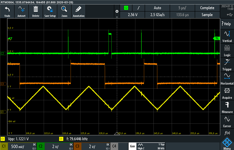
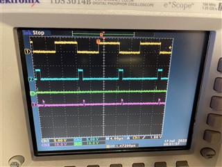
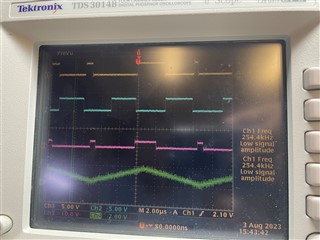
   我首先使用 F28379D TI EVM 板进行实验、并设置死区时间 RED = 0、FED = 0、但仍会有问题。 您能帮助我们根据随附的示例程序对其进行测试吗?

/*
 * Copyright (c) 2020 Texas Instruments Incorporated - http://www.ti.com
 * All rights reserved.
 *
 * Redistribution and use in source and binary forms, with or without
 * modification, are permitted provided that the following conditions
 * are met:
 *
 * *  Redistributions of source code must retain the above copyright
 *    notice, this list of conditions and the following disclaimer.
 *
 * *  Redistributions in binary form must reproduce the above copyright
 *    notice, this list of conditions and the following disclaimer in the
 *    documentation and/or other materials provided with the distribution.
 *
 * *  Neither the name of Texas Instruments Incorporated nor the names of
 *    its contributors may be used to endorse or promote products derived
 *    from this software without specific prior written permission.
 *
 * THIS SOFTWARE IS PROVIDED BY THE COPYRIGHT HOLDERS AND CONTRIBUTORS "AS IS"
 * AND ANY EXPRESS OR IMPLIED WARRANTIES, INCLUDING, BUT NOT LIMITED TO,
 * THE IMPLIED WARRANTIES OF MERCHANTABILITY AND FITNESS FOR A PARTICULAR
 * PURPOSE ARE DISCLAIMED. IN NO EVENT SHALL THE COPYRIGHT OWNER OR
 * CONTRIBUTORS BE LIABLE FOR ANY DIRECT, INDIRECT, INCIDENTAL, SPECIAL,
 * EXEMPLARY, OR CONSEQUENTIAL DAMAGES (INCLUDING, BUT NOT LIMITED TO,
 * PROCUREMENT OF SUBSTITUTE GOODS OR SERVICES; LOSS OF USE, DATA, OR PROFITS;
 * OR BUSINESS INTERRUPTION) HOWEVER CAUSED AND ON ANY THEORY OF LIABILITY,
 * WHETHER IN CONTRACT, STRICT LIABILITY, OR TORT (INCLUDING NEGLIGENCE OR
 * OTHERWISE) ARISING IN ANY WAY OUT OF THE USE OF THIS SOFTWARE,
 * EVEN IF ADVISED OF THE POSSIBILITY OF SUCH DAMAGE.
 *
 */

#include "board.h"

void Board_init()
{
	EALLOW;

	PinMux_init();
	SYNC_init();
	CMPSS_init();
	EPWM_init();
	EPWMXBAR_init();

	EDIS;
}

void PinMux_init()
{
	//
	// EPWM7 -> myEPWM7 Pinmux
	//
	GPIO_setPinConfig(GPIO_12_EPWM7A);
	GPIO_setPinConfig(GPIO_13_EPWM7B);

}

 
void CMPSS_init(){

	//myCMPSS0 initialization
	// Sets the configuration for the high comparator.
	CMPSS_configHighComparator(myCMPSS0_BASE,(CMPSS_INSRC_DAC | CMPSS_OR_ASYNC_OUT_W_FILT));
	// Sets the configuration for the high comparator.
	CMPSS_configLowComparator(myCMPSS0_BASE,(CMPSS_INSRC_DAC | CMPSS_INV_INVERTED | CMPSS_OR_ASYNC_OUT_W_FILT));
	// Sets the configuration for the internal comparator DACs.
	//  - ePWM module must be configured before using here.
	CMPSS_configDAC(myCMPSS0_BASE,(CMPSS_DACVAL_PWMSYNC | CMPSS_DACREF_VDDA | CMPSS_DACSRC_SHDW));
	// Sets the value of the internal DAC of the high comparator.
	CMPSS_setDACValueHigh(myCMPSS0_BASE,620U);
	// Sets the value of the internal DAC of the low comparator.
	CMPSS_setDACValueLow(myCMPSS0_BASE,124U);
	//  Configures the digital filter of the high comparator.
	CMPSS_configFilterHigh(myCMPSS0_BASE, 0U, 1U, 1U);
	// Configures the digital filter of the low comparator.
	CMPSS_configFilterLow(myCMPSS0_BASE, 0U, 1U, 1U);
	// Sets the output signal configuration for the high comparator.
	CMPSS_configOutputsHigh(myCMPSS0_BASE,(CMPSS_TRIPOUT_ASYNC_COMP | CMPSS_TRIP_SYNC_COMP));
	// Sets the output signal configuration for the low comparator.
	CMPSS_configOutputsLow(myCMPSS0_BASE,(CMPSS_TRIPOUT_ASYNC_COMP | CMPSS_TRIP_SYNC_COMP));
	// Sets the comparator hysteresis settings.
	CMPSS_setHysteresis(myCMPSS0_BASE,1U);
	// Configures the comparator subsystem's ramp generator.
	CMPSS_configRamp(myCMPSS0_BASE,0U,0U,0U,1U,true);
	// Disables reset of HIGH comparator digital filter output latch on PWMSYNC
	CMPSS_disableLatchResetOnPWMSYNCHigh(myCMPSS0_BASE);
	// Disables reset of LOW comparator digital filter output latch on PWMSYNC
	CMPSS_disableLatchResetOnPWMSYNCLow(myCMPSS0_BASE);
	// Configures whether or not the digital filter latches are reset by PWMSYNC
	CMPSS_configLatchOnPWMSYNC(myCMPSS0_BASE,false,false);
	// Enables the CMPSS module.
	CMPSS_enableModule(myCMPSS0_BASE);
	// Delay for CMPSS DAC to power up.
	DEVICE_DELAY_US(500);
}
void EPWM_init(){
    EPWM_setEmulationMode(myEPWM7_BASE, EPWM_EMULATION_FREE_RUN);	
    EPWM_setClockPrescaler(myEPWM7_BASE, EPWM_CLOCK_DIVIDER_1, EPWM_HSCLOCK_DIVIDER_1);	
    EPWM_setTimeBasePeriod(myEPWM7_BASE, 600);	
    EPWM_setTimeBaseCounter(myEPWM7_BASE, 0);	
    EPWM_setTimeBaseCounterMode(myEPWM7_BASE, EPWM_COUNTER_MODE_UP);	
    EPWM_disablePhaseShiftLoad(myEPWM7_BASE);	
    EPWM_setPhaseShift(myEPWM7_BASE, 0);	
    EPWM_setSyncOutPulseMode(myEPWM7_BASE, EPWM_SYNC_OUT_PULSE_ON_COUNTER_ZERO);	
    EPWM_setCounterCompareValue(myEPWM7_BASE, EPWM_COUNTER_COMPARE_A, 300);	
    EPWM_setCounterCompareShadowLoadMode(myEPWM7_BASE, EPWM_COUNTER_COMPARE_A, EPWM_COMP_LOAD_ON_CNTR_ZERO);	
    EPWM_setCounterCompareValue(myEPWM7_BASE, EPWM_COUNTER_COMPARE_B, 48);	
    EPWM_setCounterCompareShadowLoadMode(myEPWM7_BASE, EPWM_COUNTER_COMPARE_B, EPWM_COMP_LOAD_ON_CNTR_ZERO);	
    EPWM_setCounterCompareValue(myEPWM7_BASE, EPWM_COUNTER_COMPARE_C, 181);	
    EPWM_setCounterCompareValue(myEPWM7_BASE, EPWM_COUNTER_COMPARE_D, 300);	
    EPWM_setActionQualifierT1TriggerSource(myEPWM7_BASE, EPWM_AQ_TRIGGER_EVENT_TRIG_DCA_2);	
    EPWM_setActionQualifierT2TriggerSource(myEPWM7_BASE, EPWM_AQ_TRIGGER_EVENT_TRIG_DCA_2);	
    EPWM_setActionQualifierAction(myEPWM7_BASE, EPWM_AQ_OUTPUT_A, EPWM_AQ_OUTPUT_HIGH, EPWM_AQ_OUTPUT_ON_TIMEBASE_ZERO);	
    EPWM_setActionQualifierAction(myEPWM7_BASE, EPWM_AQ_OUTPUT_A, EPWM_AQ_OUTPUT_NO_CHANGE, EPWM_AQ_OUTPUT_ON_TIMEBASE_PERIOD);	
    EPWM_setActionQualifierAction(myEPWM7_BASE, EPWM_AQ_OUTPUT_A, EPWM_AQ_OUTPUT_LOW, EPWM_AQ_OUTPUT_ON_TIMEBASE_UP_CMPA);	
    EPWM_setActionQualifierAction(myEPWM7_BASE, EPWM_AQ_OUTPUT_A, EPWM_AQ_OUTPUT_NO_CHANGE, EPWM_AQ_OUTPUT_ON_TIMEBASE_DOWN_CMPA);	
    EPWM_setActionQualifierAction(myEPWM7_BASE, EPWM_AQ_OUTPUT_A, EPWM_AQ_OUTPUT_NO_CHANGE, EPWM_AQ_OUTPUT_ON_TIMEBASE_UP_CMPB);	
    EPWM_setActionQualifierAction(myEPWM7_BASE, EPWM_AQ_OUTPUT_A, EPWM_AQ_OUTPUT_NO_CHANGE, EPWM_AQ_OUTPUT_ON_TIMEBASE_DOWN_CMPB);	
    EPWM_setActionQualifierT1TriggerSource(myEPWM7_BASE, EPWM_AQ_TRIGGER_EVENT_TRIG_DCA_2);	
    EPWM_setActionQualifierT2TriggerSource(myEPWM7_BASE, EPWM_AQ_TRIGGER_EVENT_TRIG_DCA_2);	
    EPWM_setActionQualifierAction(myEPWM7_BASE, EPWM_AQ_OUTPUT_B, EPWM_AQ_OUTPUT_LOW, EPWM_AQ_OUTPUT_ON_TIMEBASE_ZERO);	
    EPWM_setActionQualifierAction(myEPWM7_BASE, EPWM_AQ_OUTPUT_B, EPWM_AQ_OUTPUT_NO_CHANGE, EPWM_AQ_OUTPUT_ON_TIMEBASE_PERIOD);	
    EPWM_setActionQualifierAction(myEPWM7_BASE, EPWM_AQ_OUTPUT_B, EPWM_AQ_OUTPUT_HIGH, EPWM_AQ_OUTPUT_ON_TIMEBASE_UP_CMPA);	
    EPWM_setActionQualifierAction(myEPWM7_BASE, EPWM_AQ_OUTPUT_B, EPWM_AQ_OUTPUT_NO_CHANGE, EPWM_AQ_OUTPUT_ON_TIMEBASE_DOWN_CMPA);	
    EPWM_setActionQualifierAction(myEPWM7_BASE, EPWM_AQ_OUTPUT_B, EPWM_AQ_OUTPUT_NO_CHANGE, EPWM_AQ_OUTPUT_ON_TIMEBASE_UP_CMPB);	
    EPWM_setActionQualifierAction(myEPWM7_BASE, EPWM_AQ_OUTPUT_B, EPWM_AQ_OUTPUT_NO_CHANGE, EPWM_AQ_OUTPUT_ON_TIMEBASE_DOWN_CMPB);	
    EPWM_setTripZoneAction(myEPWM7_BASE, EPWM_TZ_ACTION_EVENT_TZA, EPWM_TZ_ACTION_LOW);	
    EPWM_setTripZoneAction(myEPWM7_BASE, EPWM_TZ_ACTION_EVENT_TZB, EPWM_TZ_ACTION_LOW);	
    EPWM_setTripZoneAction(myEPWM7_BASE, EPWM_TZ_ACTION_EVENT_DCAEVT1, EPWM_TZ_ACTION_DISABLE);	
    EPWM_setTripZoneAction(myEPWM7_BASE, EPWM_TZ_ACTION_EVENT_DCAEVT2, EPWM_TZ_ACTION_DISABLE);	
    EPWM_setTripZoneAction(myEPWM7_BASE, EPWM_TZ_ACTION_EVENT_DCBEVT1, EPWM_TZ_ACTION_DISABLE);	
    EPWM_setTripZoneAction(myEPWM7_BASE, EPWM_TZ_ACTION_EVENT_DCBEVT2, EPWM_TZ_ACTION_DISABLE);	
    EPWM_enableTripZoneSignals(myEPWM7_BASE, EPWM_TZ_SIGNAL_DCAEVT2);	
    EPWM_selectDigitalCompareTripInput(myEPWM7_BASE, EPWM_DC_TRIP_TRIPIN4, EPWM_DC_TYPE_DCAH);	
    EPWM_selectDigitalCompareTripInput(myEPWM7_BASE, EPWM_DC_TRIP_TRIPIN4, EPWM_DC_TYPE_DCAL);	
    EPWM_setTripZoneDigitalCompareEventCondition(myEPWM7_BASE, EPWM_TZ_DC_OUTPUT_A2, EPWM_TZ_EVENT_DCXL_HIGH);	
    EPWM_setDigitalCompareEventSource(myEPWM7_BASE, EPWM_DC_MODULE_A, EPWM_DC_EVENT_1, EPWM_DC_EVENT_SOURCE_FILT_SIGNAL);	
    EPWM_setDigitalCompareEventSource(myEPWM7_BASE, EPWM_DC_MODULE_A, EPWM_DC_EVENT_2, EPWM_DC_EVENT_SOURCE_FILT_SIGNAL);	
    EPWM_selectDigitalCompareTripInput(myEPWM7_BASE, EPWM_DC_TRIP_TRIPIN4, EPWM_DC_TYPE_DCBH);	
    EPWM_selectDigitalCompareTripInput(myEPWM7_BASE, EPWM_DC_TRIP_TRIPIN4, EPWM_DC_TYPE_DCBL);	
    EPWM_setDigitalCompareFilterInput(myEPWM7_BASE, EPWM_DC_WINDOW_SOURCE_DCAEVT2);	
    EPWM_enableDigitalCompareBlankingWindow(myEPWM7_BASE);	
    EPWM_setDigitalCompareBlankingEvent(myEPWM7_BASE, EPWM_DC_WINDOW_START_TBCTR_ZERO);	
    EPWM_setDigitalCompareWindowOffset(myEPWM7_BASE, 576);	
    EPWM_setDigitalCompareWindowLength(myEPWM7_BASE, 84);	
    EPWM_setDeadBandDelayPolarity(myEPWM7_BASE, EPWM_DB_FED, EPWM_DB_POLARITY_ACTIVE_LOW);	
    EPWM_setDeadBandOutputSwapMode(myEPWM7_BASE, EPWM_DB_OUTPUT_A, true);	
    EPWM_setDeadBandOutputSwapMode(myEPWM7_BASE, EPWM_DB_OUTPUT_B, true);	
    EPWM_enableInterrupt(myEPWM7_BASE);	
    EPWM_setInterruptSource(myEPWM7_BASE, EPWM_INT_TBCTR_U_CMPD);	
    EPWM_setInterruptEventCount(myEPWM7_BASE, 1);	
    EPWM_enableADCTrigger(myEPWM7_BASE, EPWM_SOC_A);	
    EPWM_setADCTriggerSource(myEPWM7_BASE, EPWM_SOC_A, EPWM_SOC_TBCTR_U_CMPC);	
    EPWM_setADCTriggerEventPrescale(myEPWM7_BASE, EPWM_SOC_A, 1);	
}

void EPWMXBAR_init(){
	//myEPWMXBAR0 initialization
		
	XBAR_setEPWMMuxConfig(XBAR_TRIP4, XBAR_EPWM_MUX07_CMPSS4_CTRIPL);
	XBAR_enableEPWMMux(XBAR_TRIP4, XBAR_MUX07);

}
void SYNC_init(){
	SysCtl_setSyncOutputConfig(SYSCTL_SYNC_OUT_SRC_EPWM7SYNCOUT);
	// For EPWM1, the sync input is: SYSCTL_SYNC_IN_SRC_EXTSYNCIN1
	SysCtl_setSyncInputConfig(SYSCTL_SYNC_IN_EPWM4, SYSCTL_SYNC_IN_SRC_EPWM1SYNCOUT);
	SysCtl_setSyncInputConfig(SYSCTL_SYNC_IN_EPWM7, SYSCTL_SYNC_IN_SRC_EPWM1SYNCOUT);
	SysCtl_setSyncInputConfig(SYSCTL_SYNC_IN_EPWM10, SYSCTL_SYNC_IN_SRC_EPWM7SYNCOUT);
	SysCtl_setSyncInputConfig(SYSCTL_SYNC_IN_ECAP1, SYSCTL_SYNC_IN_SRC_EPWM1SYNCOUT);
	SysCtl_setSyncInputConfig(SYSCTL_SYNC_IN_ECAP4, SYSCTL_SYNC_IN_SRC_EPWM1SYNCOUT);
	// SOCA
	SysCtl_enableExtADCSOCSource(0);
	// SOCB
	SysCtl_enableExtADCSOCSource(0);
	SysCtl_lockSyncSelect();
}

  • 请注意,本文内容源自机器翻译,可能存在语法或其它翻译错误,仅供参考。如需获取准确内容,请参阅链接中的英语原文或自行翻译。

    尊敬的 Poyi:

    我试图重现此问题、但似乎无法获得您看到的相同输出。 这是我随附的 SysConfig 代码和我在示波器上看到的输出。 您能否尝试一下、看看我的设置中是否缺少某些内容? 我把你和我提供的板吹散了。c 它们看起来是一样的。

    通道1:ePWM7A

    CH2:ePWM7B

    CH3:使用 OUTPUTXBAR 在 GPIO15上实现 CTRIPL

    CH4:信号发生器转至 CMPIN4P

    主代码:

    //
    // Included Files
    //
    #include "driverlib.h"
    #include "device.h"
    #include "board.h"
    void INT_myEPWM7_ISR(void);
    
    void INT_myEPWM7_ISR(void){
    
    }
    //
    // Main
    //
    void main(void)
    {
        //
        // Initialize device clock and peripherals
        //
        Device_init();
    
        //
        // Disable pin locks and enable internal pull-ups.
        //
        Device_initGPIO();
    
        //
        // Initialize PIE and clear PIE registers. Disables CPU interrupts.
        //
        Interrupt_initModule();
    
        //
        // Initialize the PIE vector table with pointers to the shell Interrupt
        // Service Routines (ISR).
        //
        Interrupt_initVectorTable();
    
        //
        // For this case just init GPIO pins for ePWM1, ePWM2, ePWM3
        //
        Board_init();
    
        EPWM_setRisingEdgeDelayCount(myEPWM7_BASE, 50);
        EPWM_setFallingEdgeDelayCount(myEPWM7_BASE, 80);
    
        //
        // Disable sync(Freeze clock to PWM as well)
        //
        SysCtl_disablePeripheral(SYSCTL_PERIPH_CLK_TBCLKSYNC);
    
        //
        // Enable sync and clock to PWM
        //
        SysCtl_enablePeripheral(SYSCTL_PERIPH_CLK_TBCLKSYNC);
    
        //
        // Enable global Interrupts and higher priority real-time debug events:
        //
        EINT;  // Enable Global interrupt INTM
        ERTM;  // Enable Global realtime interrupt DBGM
    
        //
        // IDLE loop. Just sit and loop forever (optional):
        //
        for(;;)
        {
            asm ("  NOP");
        }
    }
    

    SysConfig board.c:

    /*
     * Copyright (c) 2020 Texas Instruments Incorporated - http://www.ti.com
     * All rights reserved.
     *
     * Redistribution and use in source and binary forms, with or without
     * modification, are permitted provided that the following conditions
     * are met:
     *
     * *  Redistributions of source code must retain the above copyright
     *    notice, this list of conditions and the following disclaimer.
     *
     * *  Redistributions in binary form must reproduce the above copyright
     *    notice, this list of conditions and the following disclaimer in the
     *    documentation and/or other materials provided with the distribution.
     *
     * *  Neither the name of Texas Instruments Incorporated nor the names of
     *    its contributors may be used to endorse or promote products derived
     *    from this software without specific prior written permission.
     *
     * THIS SOFTWARE IS PROVIDED BY THE COPYRIGHT HOLDERS AND CONTRIBUTORS "AS IS"
     * AND ANY EXPRESS OR IMPLIED WARRANTIES, INCLUDING, BUT NOT LIMITED TO,
     * THE IMPLIED WARRANTIES OF MERCHANTABILITY AND FITNESS FOR A PARTICULAR
     * PURPOSE ARE DISCLAIMED. IN NO EVENT SHALL THE COPYRIGHT OWNER OR
     * CONTRIBUTORS BE LIABLE FOR ANY DIRECT, INDIRECT, INCIDENTAL, SPECIAL,
     * EXEMPLARY, OR CONSEQUENTIAL DAMAGES (INCLUDING, BUT NOT LIMITED TO,
     * PROCUREMENT OF SUBSTITUTE GOODS OR SERVICES; LOSS OF USE, DATA, OR PROFITS;
     * OR BUSINESS INTERRUPTION) HOWEVER CAUSED AND ON ANY THEORY OF LIABILITY,
     * WHETHER IN CONTRACT, STRICT LIABILITY, OR TORT (INCLUDING NEGLIGENCE OR
     * OTHERWISE) ARISING IN ANY WAY OUT OF THE USE OF THIS SOFTWARE,
     * EVEN IF ADVISED OF THE POSSIBILITY OF SUCH DAMAGE.
     *
     */
    
    #include "board.h"
    
    //*****************************************************************************
    //
    // Board Configurations
    // Initializes the rest of the modules. 
    // Call this function in your application if you wish to do all module 
    // initialization.
    // If you wish to not use some of the initializations, instead of the 
    // Board_init use the individual Module_inits
    //
    //*****************************************************************************
    void Board_init()
    {
    	EALLOW;
    
    	PinMux_init();
    	SYNC_init();
    	ADC_init();
    	CMPSS_init();
    	EPWM_init();
    	EPWMXBAR_init();
    	OUTPUTXBAR_init();
    	INTERRUPT_init();
    
    	EDIS;
    }
    
    //*****************************************************************************
    //
    // PINMUX Configurations
    //
    //*****************************************************************************
    void PinMux_init()
    {
    	//
    	// PinMux for modules assigned to CPU1
    	//
    	
    	//
    	// EPWM7 -> myEPWM7 Pinmux
    	//
    	GPIO_setPinConfig(myEPWM7_EPWMA_PIN_CONFIG);
    	GPIO_setPadConfig(myEPWM7_EPWMA_GPIO, GPIO_PIN_TYPE_STD);
    	GPIO_setQualificationMode(myEPWM7_EPWMA_GPIO, GPIO_QUAL_SYNC);
    
    	GPIO_setPinConfig(myEPWM7_EPWMB_PIN_CONFIG);
    	GPIO_setPadConfig(myEPWM7_EPWMB_GPIO, GPIO_PIN_TYPE_STD);
    	GPIO_setQualificationMode(myEPWM7_EPWMB_GPIO, GPIO_QUAL_SYNC);
    
    	//
    	// OUTPUTXBAR4 -> myOUTPUTXBAR0 Pinmux
    	//
    	GPIO_setPinConfig(myOUTPUTXBAR0_OUTPUTXBAR_PIN_CONFIG);
    
    }
    
    //*****************************************************************************
    //
    // ADC Configurations
    //
    //*****************************************************************************
    void ADC_init(){
    	myADC0_init();
    }
    
    void myADC0_init(){
    	//
    	// ADC Initialization: Write ADC configurations and power up the ADC
    	//
    	// Configures the analog-to-digital converter module prescaler.
    	//
    	ADC_setPrescaler(myADC0_BASE, ADC_CLK_DIV_1_0);
    	//
    	// Configures the analog-to-digital converter resolution and signal mode.
    	//
    	ADC_setMode(myADC0_BASE, ADC_RESOLUTION_12BIT, ADC_MODE_SINGLE_ENDED);
    	//
    	// Sets the timing of the end-of-conversion pulse
    	//
    	ADC_setInterruptPulseMode(myADC0_BASE, ADC_PULSE_END_OF_ACQ_WIN);
    	//
    	// Powers up the analog-to-digital converter core.
    	//
    	ADC_enableConverter(myADC0_BASE);
    	//
    	// Delay for 1ms to allow ADC time to power up
    	//
    	DEVICE_DELAY_US(500);
    	//
    	// SOC Configuration: Setup ADC EPWM channel and trigger settings
    	//
    	// Disables SOC burst mode.
    	//
    	ADC_disableBurstMode(myADC0_BASE);
    	//
    	// Sets the priority mode of the SOCs.
    	//
    	ADC_setSOCPriority(myADC0_BASE, ADC_PRI_ALL_ROUND_ROBIN);
    	//
    	// Start of Conversion 0 Configuration
    	//
    	//
    	// Configures a start-of-conversion (SOC) in the ADC and its interrupt SOC trigger.
    	// 	  	SOC number		: 0
    	//	  	Trigger			: ADC_TRIGGER_SW_ONLY
    	//	  	Channel			: ADC_CH_ADCIN0
    	//	 	Sample Window	: 1 SYSCLK cycles
    	//		Interrupt Trigger: ADC_INT_SOC_TRIGGER_NONE
    	//
    	ADC_setupSOC(myADC0_BASE, ADC_SOC_NUMBER0, ADC_TRIGGER_SW_ONLY, ADC_CH_ADCIN0, 1U);
    	ADC_setInterruptSOCTrigger(myADC0_BASE, ADC_SOC_NUMBER0, ADC_INT_SOC_TRIGGER_NONE);
    }
    
    //*****************************************************************************
    //
    // CMPSS Configurations
    //
    //*****************************************************************************
    void CMPSS_init(){
    	myCMPSS0_init();
    }
    
    void myCMPSS0_init(){
        //
        // Sets the configuration for the high comparator.
        //
        CMPSS_configHighComparator(myCMPSS0_BASE,(CMPSS_INSRC_DAC | CMPSS_OR_ASYNC_OUT_W_FILT));
        //
        // Sets the configuration for the low comparator.
        //
        CMPSS_configLowComparator(myCMPSS0_BASE,(CMPSS_INSRC_DAC | CMPSS_INV_INVERTED | CMPSS_OR_ASYNC_OUT_W_FILT));
        //
        // Sets the configuration for the internal comparator DACs.
        //
        //
        //  - ePWM module must be configured before using here.
        //
        CMPSS_configDAC(myCMPSS0_BASE,(CMPSS_DACVAL_PWMSYNC | CMPSS_DACREF_VDDA | CMPSS_DACSRC_SHDW));
        //
        // Sets the value of the internal DAC of the high comparator.
        //
        CMPSS_setDACValueHigh(myCMPSS0_BASE,620U);
        //
        // Sets the value of the internal DAC of the low comparator.
        //
        CMPSS_setDACValueLow(myCMPSS0_BASE,124U);
        //
        //  Configures the digital filter of the high comparator.
        //
        CMPSS_configFilterHigh(myCMPSS0_BASE, 0U, 1U, 1U);
        //
        // Configures the digital filter of the low comparator.
        //
        CMPSS_configFilterLow(myCMPSS0_BASE, 0U, 1U, 1U);
        //
        // Sets the output signal configuration for the high comparator.
        //
        CMPSS_configOutputsHigh(myCMPSS0_BASE,(CMPSS_TRIPOUT_ASYNC_COMP | CMPSS_TRIP_ASYNC_COMP));
        //
        // Sets the output signal configuration for the low comparator.
        //
        CMPSS_configOutputsLow(myCMPSS0_BASE,(CMPSS_TRIPOUT_ASYNC_COMP | CMPSS_TRIP_ASYNC_COMP));
        //
        // Sets the comparator hysteresis settings.
        //
        CMPSS_setHysteresis(myCMPSS0_BASE,1U);
        //
        // Configures the comparator subsystem's ramp generator.
        //
        CMPSS_configRamp(myCMPSS0_BASE,0U,0U,0U,1U,true);
        //
        // Disables reset of HIGH comparator digital filter output latch on PWMSYNC
        //
        CMPSS_disableLatchResetOnPWMSYNCHigh(myCMPSS0_BASE);
        //
        // Disables reset of LOW comparator digital filter output latch on PWMSYNC
        //
        CMPSS_disableLatchResetOnPWMSYNCLow(myCMPSS0_BASE);
        //
        // Configures whether or not the digital filter latches are reset by PWMSYNC
        //
        CMPSS_configLatchOnPWMSYNC(myCMPSS0_BASE,false,false);
        //
        // Enables the CMPSS module.
        //
        CMPSS_enableModule(myCMPSS0_BASE);
        //
        // Delay for CMPSS DAC to power up.
        //
        DEVICE_DELAY_US(500);
    }
    
    //*****************************************************************************
    //
    // EPWM Configurations
    //
    //*****************************************************************************
    void EPWM_init(){
        EPWM_setEmulationMode(myEPWM7_BASE, EPWM_EMULATION_FREE_RUN);	
        EPWM_setClockPrescaler(myEPWM7_BASE, EPWM_CLOCK_DIVIDER_1, EPWM_HSCLOCK_DIVIDER_2);	
        EPWM_setTimeBasePeriod(myEPWM7_BASE, 600);	
        EPWM_setTimeBaseCounter(myEPWM7_BASE, 0);	
        EPWM_setTimeBaseCounterMode(myEPWM7_BASE, EPWM_COUNTER_MODE_UP);	
        EPWM_disablePhaseShiftLoad(myEPWM7_BASE);	
        EPWM_setPhaseShift(myEPWM7_BASE, 0);	
        EPWM_setSyncOutPulseMode(myEPWM7_BASE, EPWM_SYNC_OUT_PULSE_ON_COUNTER_ZERO);	
        EPWM_setCounterCompareValue(myEPWM7_BASE, EPWM_COUNTER_COMPARE_A, 300);	
        EPWM_setCounterCompareShadowLoadMode(myEPWM7_BASE, EPWM_COUNTER_COMPARE_A, EPWM_COMP_LOAD_ON_CNTR_ZERO);	
        EPWM_setCounterCompareValue(myEPWM7_BASE, EPWM_COUNTER_COMPARE_B, 48);	
        EPWM_setCounterCompareShadowLoadMode(myEPWM7_BASE, EPWM_COUNTER_COMPARE_B, EPWM_COMP_LOAD_ON_CNTR_ZERO);	
        EPWM_setCounterCompareValue(myEPWM7_BASE, EPWM_COUNTER_COMPARE_C, 181);	
        EPWM_setCounterCompareValue(myEPWM7_BASE, EPWM_COUNTER_COMPARE_D, 300);	
        EPWM_setActionQualifierT1TriggerSource(myEPWM7_BASE, EPWM_AQ_TRIGGER_EVENT_TRIG_DCA_2);	
        EPWM_setActionQualifierT2TriggerSource(myEPWM7_BASE, EPWM_AQ_TRIGGER_EVENT_TRIG_DCA_2);	
        EPWM_setActionQualifierAction(myEPWM7_BASE, EPWM_AQ_OUTPUT_A, EPWM_AQ_OUTPUT_HIGH, EPWM_AQ_OUTPUT_ON_TIMEBASE_ZERO);	
        EPWM_setActionQualifierAction(myEPWM7_BASE, EPWM_AQ_OUTPUT_A, EPWM_AQ_OUTPUT_NO_CHANGE, EPWM_AQ_OUTPUT_ON_TIMEBASE_PERIOD);	
        EPWM_setActionQualifierAction(myEPWM7_BASE, EPWM_AQ_OUTPUT_A, EPWM_AQ_OUTPUT_LOW, EPWM_AQ_OUTPUT_ON_TIMEBASE_UP_CMPA);	
        EPWM_setActionQualifierAction(myEPWM7_BASE, EPWM_AQ_OUTPUT_A, EPWM_AQ_OUTPUT_NO_CHANGE, EPWM_AQ_OUTPUT_ON_TIMEBASE_DOWN_CMPA);	
        EPWM_setActionQualifierAction(myEPWM7_BASE, EPWM_AQ_OUTPUT_A, EPWM_AQ_OUTPUT_NO_CHANGE, EPWM_AQ_OUTPUT_ON_TIMEBASE_UP_CMPB);	
        EPWM_setActionQualifierAction(myEPWM7_BASE, EPWM_AQ_OUTPUT_A, EPWM_AQ_OUTPUT_NO_CHANGE, EPWM_AQ_OUTPUT_ON_TIMEBASE_DOWN_CMPB);	
        EPWM_setActionQualifierAction(myEPWM7_BASE, EPWM_AQ_OUTPUT_B, EPWM_AQ_OUTPUT_LOW, EPWM_AQ_OUTPUT_ON_TIMEBASE_ZERO);	
        EPWM_setActionQualifierAction(myEPWM7_BASE, EPWM_AQ_OUTPUT_B, EPWM_AQ_OUTPUT_NO_CHANGE, EPWM_AQ_OUTPUT_ON_TIMEBASE_PERIOD);	
        EPWM_setActionQualifierAction(myEPWM7_BASE, EPWM_AQ_OUTPUT_B, EPWM_AQ_OUTPUT_HIGH, EPWM_AQ_OUTPUT_ON_TIMEBASE_UP_CMPA);	
        EPWM_setActionQualifierAction(myEPWM7_BASE, EPWM_AQ_OUTPUT_B, EPWM_AQ_OUTPUT_NO_CHANGE, EPWM_AQ_OUTPUT_ON_TIMEBASE_DOWN_CMPA);	
        EPWM_setActionQualifierAction(myEPWM7_BASE, EPWM_AQ_OUTPUT_B, EPWM_AQ_OUTPUT_NO_CHANGE, EPWM_AQ_OUTPUT_ON_TIMEBASE_UP_CMPB);	
        EPWM_setActionQualifierAction(myEPWM7_BASE, EPWM_AQ_OUTPUT_B, EPWM_AQ_OUTPUT_NO_CHANGE, EPWM_AQ_OUTPUT_ON_TIMEBASE_DOWN_CMPB);	
        EPWM_setDeadBandDelayPolarity(myEPWM7_BASE, EPWM_DB_FED, EPWM_DB_POLARITY_ACTIVE_LOW);	
        EPWM_setDeadBandDelayMode(myEPWM7_BASE, EPWM_DB_RED, true);	
        EPWM_setRisingEdgeDelayCount(myEPWM7_BASE, 20);	
        EPWM_setDeadBandDelayMode(myEPWM7_BASE, EPWM_DB_FED, true);	
        EPWM_setFallingEdgeDelayCount(myEPWM7_BASE, 30);	
        EPWM_setDeadBandOutputSwapMode(myEPWM7_BASE, EPWM_DB_OUTPUT_A, true);	
        EPWM_setDeadBandOutputSwapMode(myEPWM7_BASE, EPWM_DB_OUTPUT_B, true);	
        EPWM_setTripZoneAction(myEPWM7_BASE, EPWM_TZ_ACTION_EVENT_TZA, EPWM_TZ_ACTION_LOW);	
        EPWM_setTripZoneAction(myEPWM7_BASE, EPWM_TZ_ACTION_EVENT_TZB, EPWM_TZ_ACTION_LOW);	
        EPWM_setTripZoneAction(myEPWM7_BASE, EPWM_TZ_ACTION_EVENT_DCAEVT1, EPWM_TZ_ACTION_DISABLE);	
        EPWM_setTripZoneAction(myEPWM7_BASE, EPWM_TZ_ACTION_EVENT_DCAEVT2, EPWM_TZ_ACTION_DISABLE);	
        EPWM_setTripZoneAction(myEPWM7_BASE, EPWM_TZ_ACTION_EVENT_DCBEVT1, EPWM_TZ_ACTION_DISABLE);	
        EPWM_setTripZoneAction(myEPWM7_BASE, EPWM_TZ_ACTION_EVENT_DCBEVT2, EPWM_TZ_ACTION_DISABLE);	
        EPWM_enableTripZoneSignals(myEPWM7_BASE, EPWM_TZ_SIGNAL_DCAEVT2);	
        EPWM_selectDigitalCompareTripInput(myEPWM7_BASE, EPWM_DC_TRIP_TRIPIN4, EPWM_DC_TYPE_DCAH);	
        EPWM_selectDigitalCompareTripInput(myEPWM7_BASE, EPWM_DC_TRIP_TRIPIN4, EPWM_DC_TYPE_DCAL);	
        EPWM_setTripZoneDigitalCompareEventCondition(myEPWM7_BASE, EPWM_TZ_DC_OUTPUT_A1, EPWM_TZ_EVENT_DCXH_HIGH);	
        EPWM_setDigitalCompareEventSource(myEPWM7_BASE, EPWM_DC_MODULE_A, EPWM_DC_EVENT_1, EPWM_DC_EVENT_SOURCE_FILT_SIGNAL);	
        EPWM_setDigitalCompareEventSource(myEPWM7_BASE, EPWM_DC_MODULE_A, EPWM_DC_EVENT_2, EPWM_DC_EVENT_SOURCE_FILT_SIGNAL);	
        EPWM_selectDigitalCompareTripInput(myEPWM7_BASE, EPWM_DC_TRIP_TRIPIN4, EPWM_DC_TYPE_DCBH);	
        EPWM_selectDigitalCompareTripInput(myEPWM7_BASE, EPWM_DC_TRIP_TRIPIN4, EPWM_DC_TYPE_DCBL);	
        EPWM_setDigitalCompareFilterInput(myEPWM7_BASE, EPWM_DC_WINDOW_SOURCE_DCAEVT2);	
        EPWM_enableDigitalCompareBlankingWindow(myEPWM7_BASE);	
        EPWM_setDigitalCompareBlankingEvent(myEPWM7_BASE, EPWM_DC_WINDOW_START_TBCTR_ZERO);	
        EPWM_setDigitalCompareWindowOffset(myEPWM7_BASE, 576);	
        EPWM_setDigitalCompareWindowLength(myEPWM7_BASE, 84);	
        EPWM_enableInterrupt(myEPWM7_BASE);	
        EPWM_setInterruptSource(myEPWM7_BASE, EPWM_INT_TBCTR_U_CMPD);	
        EPWM_setInterruptEventCount(myEPWM7_BASE, 1);	
        EPWM_enableADCTrigger(myEPWM7_BASE, EPWM_SOC_A);	
        EPWM_setADCTriggerSource(myEPWM7_BASE, EPWM_SOC_A, EPWM_SOC_TBCTR_U_CMPC);	
        EPWM_setADCTriggerEventPrescale(myEPWM7_BASE, EPWM_SOC_A, 1);	
    }
    
    //*****************************************************************************
    //
    // EPWMXBAR Configurations
    //
    //*****************************************************************************
    void EPWMXBAR_init(){
    	XBAR_TRIP4_init();
    }
    
    void XBAR_TRIP4_init(){
    		
    	XBAR_setEPWMMuxConfig(XBAR_TRIP4, XBAR_EPWM_MUX07_CMPSS4_CTRIPL);
    	XBAR_enableEPWMMux(XBAR_TRIP4, XBAR_MUX07);
    }
    
    //*****************************************************************************
    //
    // INTERRUPT Configurations
    //
    //*****************************************************************************
    void INTERRUPT_init(){
    	
    	// Interrupt Setings for INT_myEPWM7
    	Interrupt_register(INT_myEPWM7, &INT_myEPWM7_ISR);
    	Interrupt_enable(INT_myEPWM7);
    }
    //*****************************************************************************
    //
    // OUTPUTXBAR Configurations
    //
    //*****************************************************************************
    void OUTPUTXBAR_init(){
    	myOUTPUTXBAR0_init();
    }
    
    void myOUTPUTXBAR0_init(){
    	XBAR_setOutputLatchMode(myOUTPUTXBAR0, false);
    	XBAR_invertOutputSignal(myOUTPUTXBAR0, false);
    		
    	//
    	//Mux configuration
    	//
    	XBAR_setOutputMuxConfig(myOUTPUTXBAR0, XBAR_OUT_MUX07_CMPSS4_CTRIPOUTL);
    	XBAR_enableOutputMux(myOUTPUTXBAR0, XBAR_MUX07);
    }
    
    //*****************************************************************************
    //
    // SYNC Scheme Configurations
    //
    //*****************************************************************************
    void SYNC_init(){
    	SysCtl_setSyncOutputConfig(SYSCTL_SYNC_OUT_SRC_EPWM1SYNCOUT);
    	//
    	// For EPWM1, the sync input is: SYSCTL_SYNC_IN_SRC_EXTSYNCIN1
    	//
    	SysCtl_setSyncInputConfig(SYSCTL_SYNC_IN_EPWM4, SYSCTL_SYNC_IN_SRC_EPWM1SYNCOUT);
    	SysCtl_setSyncInputConfig(SYSCTL_SYNC_IN_EPWM7, SYSCTL_SYNC_IN_SRC_EPWM1SYNCOUT);
    	SysCtl_setSyncInputConfig(SYSCTL_SYNC_IN_EPWM10, SYSCTL_SYNC_IN_SRC_EPWM1SYNCOUT);
    	SysCtl_setSyncInputConfig(SYSCTL_SYNC_IN_ECAP1, SYSCTL_SYNC_IN_SRC_EPWM1SYNCOUT);
    	SysCtl_setSyncInputConfig(SYSCTL_SYNC_IN_ECAP4, SYSCTL_SYNC_IN_SRC_EPWM1SYNCOUT);
    	//
    	// SOCA
    	//
    	SysCtl_enableExtADCSOCSource(0);
    	//
    	// SOCB
    	//
    	SysCtl_enableExtADCSOCSource(0);
    	SysCtl_lockSyncSelect();
    }
    

    board.h:

    /*
     * Copyright (c) 2020 Texas Instruments Incorporated - http://www.ti.com
     * All rights reserved.
     *
     * Redistribution and use in source and binary forms, with or without
     * modification, are permitted provided that the following conditions
     * are met:
     *
     * *  Redistributions of source code must retain the above copyright
     *    notice, this list of conditions and the following disclaimer.
     *
     * *  Redistributions in binary form must reproduce the above copyright
     *    notice, this list of conditions and the following disclaimer in the
     *    documentation and/or other materials provided with the distribution.
     *
     * *  Neither the name of Texas Instruments Incorporated nor the names of
     *    its contributors may be used to endorse or promote products derived
     *    from this software without specific prior written permission.
     *
     * THIS SOFTWARE IS PROVIDED BY THE COPYRIGHT HOLDERS AND CONTRIBUTORS "AS IS"
     * AND ANY EXPRESS OR IMPLIED WARRANTIES, INCLUDING, BUT NOT LIMITED TO,
     * THE IMPLIED WARRANTIES OF MERCHANTABILITY AND FITNESS FOR A PARTICULAR
     * PURPOSE ARE DISCLAIMED. IN NO EVENT SHALL THE COPYRIGHT OWNER OR
     * CONTRIBUTORS BE LIABLE FOR ANY DIRECT, INDIRECT, INCIDENTAL, SPECIAL,
     * EXEMPLARY, OR CONSEQUENTIAL DAMAGES (INCLUDING, BUT NOT LIMITED TO,
     * PROCUREMENT OF SUBSTITUTE GOODS OR SERVICES; LOSS OF USE, DATA, OR PROFITS;
     * OR BUSINESS INTERRUPTION) HOWEVER CAUSED AND ON ANY THEORY OF LIABILITY,
     * WHETHER IN CONTRACT, STRICT LIABILITY, OR TORT (INCLUDING NEGLIGENCE OR
     * OTHERWISE) ARISING IN ANY WAY OUT OF THE USE OF THIS SOFTWARE,
     * EVEN IF ADVISED OF THE POSSIBILITY OF SUCH DAMAGE.
     *
     */
    
    #ifndef BOARD_H
    #define BOARD_H
    
    //*****************************************************************************
    //
    // If building with a C++ compiler, make all of the definitions in this header
    // have a C binding.
    //
    //*****************************************************************************
    #ifdef __cplusplus
    extern "C"
    {
    #endif
    
    //
    // Included Files
    //
    
    #include "driverlib.h"
    #include "device.h"
    
    //*****************************************************************************
    //
    // PinMux Configurations
    //
    //*****************************************************************************
    
    //
    // EPWM7 -> myEPWM7 Pinmux
    //
    //
    // EPWM7A - GPIO Settings
    //
    #define GPIO_PIN_EPWM7A 12
    #define myEPWM7_EPWMA_GPIO 12
    #define myEPWM7_EPWMA_PIN_CONFIG GPIO_12_EPWM7A
    //
    // EPWM7B - GPIO Settings
    //
    #define GPIO_PIN_EPWM7B 13
    #define myEPWM7_EPWMB_GPIO 13
    #define myEPWM7_EPWMB_PIN_CONFIG GPIO_13_EPWM7B
    
    //
    // OUTPUTXBAR4 -> myOUTPUTXBAR0 Pinmux
    //
    //
    // OUTPUTXBAR4 - GPIO Settings
    //
    #define GPIO_PIN_OUTPUTXBAR4 15
    #define myOUTPUTXBAR0_OUTPUTXBAR_GPIO 15
    #define myOUTPUTXBAR0_OUTPUTXBAR_PIN_CONFIG GPIO_15_OUTPUTXBAR4
    
    //*****************************************************************************
    //
    // ADC Configurations
    //
    //*****************************************************************************
    #define myADC0_BASE ADCA_BASE
    #define myADC0_RESULT_BASE ADCARESULT_BASE
    #define myADC0_SOC0 ADC_SOC_NUMBER0
    #define myADC0_FORCE_SOC0 ADC_FORCE_SOC0
    #define myADC0_SAMPLE_WINDOW_SOC0 5
    #define myADC0_TRIGGER_SOURCE_SOC0 ADC_TRIGGER_SW_ONLY
    #define myADC0_CHANNEL_SOC0 ADC_CH_ADCIN0
    void myADC0_init();
    
    
    //*****************************************************************************
    //
    // CMPSS Configurations
    //
    //*****************************************************************************
    #define myCMPSS0_BASE CMPSS4_BASE
    #define myCMPSS0_HIGH_COMP_BASE CMPSS4_BASE    
    #define myCMPSS0_LOW_COMP_BASE CMPSS4_BASE    
    void myCMPSS0_init();
    
    //*****************************************************************************
    //
    // EPWM Configurations
    //
    //*****************************************************************************
    #define myEPWM7_BASE EPWM7_BASE
    #define myEPWM7_TBPRD 600
    #define myEPWM7_COUNTER_MODE EPWM_COUNTER_MODE_UP
    #define myEPWM7_TBPHS 0
    #define myEPWM7_CMPA 300
    #define myEPWM7_CMPB 48
    #define myEPWM7_CMPC 181
    #define myEPWM7_CMPD 300
    #define myEPWM7_DBRED 20
    #define myEPWM7_DBFED 30
    #define myEPWM7_TZA_ACTION EPWM_TZ_ACTION_LOW
    #define myEPWM7_TZB_ACTION EPWM_TZ_ACTION_LOW
    #define myEPWM7_CBC_SOURCES EPWM_TZ_SIGNAL_DCAEVT2
    #define myEPWM7_INTERRUPT_SOURCE EPWM_INT_TBCTR_U_CMPD
    
    //*****************************************************************************
    //
    // EPWMXBAR Configurations
    //
    //*****************************************************************************
    void XBAR_TRIP4_init();
    #define XBAR_TRIP4 XBAR_TRIP4
    #define XBAR_TRIP4_ENABLED_MUXES (XBAR_MUX07)
    
    //*****************************************************************************
    //
    // INTERRUPT Configurations
    //
    //*****************************************************************************
    
    // Interrupt Settings for INT_myEPWM7
    #define INT_myEPWM7 INT_EPWM7
    #define INT_myEPWM7_INTERRUPT_ACK_GROUP INTERRUPT_ACK_GROUP3
    extern __interrupt void INT_myEPWM7_ISR(void);
    
    //*****************************************************************************
    //
    // OUTPUTXBAR Configurations
    //
    //*****************************************************************************
    void myOUTPUTXBAR0_init();
    #define myOUTPUTXBAR0 XBAR_OUTPUT4
    #define myOUTPUTXBAR0_ENABLED_MUXES (XBAR_MUX07)
    
    //*****************************************************************************
    //
    // SYNC Scheme Configurations
    //
    //*****************************************************************************
    
    //*****************************************************************************
    //
    // Board Configurations
    //
    //*****************************************************************************
    void	Board_init();
    void	ADC_init();
    void	CMPSS_init();
    void	EPWM_init();
    void	EPWMXBAR_init();
    void	INTERRUPT_init();
    void	OUTPUTXBAR_init();
    void	SYNC_init();
    void	PinMux_init();
    
    //*****************************************************************************
    //
    // Mark the end of the C bindings section for C++ compilers.
    //
    //*****************************************************************************
    #ifdef __cplusplus
    }
    #endif
    
    #endif  // end of BOARD_H definition
    

    SysConfig 源代码:

    /**
     * These arguments were used when this file was generated. They will be automatically applied on subsequent loads
     * via the GUI or CLI. Run CLI with '--help' for additional information on how to override these arguments.
     * @cliArgs --device "F2837xD" --package "F2837xD_176PTP" --part "F2837xD_176PTP" --context "CPU1" --product "C2000WARE@4.03.00.00"
     * @versions {"tool":"1.16.0+2933"}
     */
    
    /**
     * Import the modules used in this configuration.
     */
    const adc         = scripting.addModule("/driverlib/adc.js", {}, false);
    const adc1        = adc.addInstance();
    const cmpss       = scripting.addModule("/driverlib/cmpss.js", {}, false);
    const cmpss1      = cmpss.addInstance();
    const epwm        = scripting.addModule("/driverlib/epwm.js", {}, false);
    const epwm1       = epwm.addInstance();
    const epwmxbar    = scripting.addModule("/driverlib/epwmxbar.js", {}, false);
    const epwmxbar1   = epwmxbar.addInstance();
    const outputxbar  = scripting.addModule("/driverlib/outputxbar.js", {}, false);
    const outputxbar1 = outputxbar.addInstance();
    const sync        = scripting.addModule("/driverlib/sync.js");
    
    /**
     * Write custom configuration values to the imported modules.
     */
    adc1.$name       = "myADC0";
    adc1.enabledSOCs = ["ADC_SOC_NUMBER0"];
    
    cmpss1.$name          = "myCMPSS0";
    cmpss1.highCompAsynch = true;
    cmpss1.lowCompAsynch  = true;
    cmpss1.lowCompInvert  = true;
    cmpss1.dacValHigh     = 620;
    cmpss1.dacValLow      = 124;
    cmpss1.hysteresisVal  = "1";
    cmpss1.enableModule   = true;
    cmpss1.dacValLoad     = "CMPSS_DACVAL_PWMSYNC";
    cmpss1.cmpssBase      = "CMPSS4_BASE";
    
    epwm1.epwmTimebase_emulationMode                                      = "EPWM_EMULATION_FREE_RUN";
    epwm1.epwmTimebase_period                                             = 600;
    epwm1.epwmTimebase_counterMode                                        = "EPWM_COUNTER_MODE_UP";
    epwm1.epwmTimebase_syncOutPulseMode                                   = "EPWM_SYNC_OUT_PULSE_ON_COUNTER_ZERO";
    epwm1.epwmCounterCompare_cmpA                                         = 300;
    epwm1.epwmCounterCompare_cmpB                                         = 48;
    epwm1.epwmCounterCompare_cmpC                                         = 181;
    epwm1.epwmCounterCompare_cmpD                                         = 300;
    epwm1.epwmActionQualifier_t1Source                                    = "EPWM_AQ_TRIGGER_EVENT_TRIG_DCA_2";
    epwm1.epwmActionQualifier_t2Source                                    = "EPWM_AQ_TRIGGER_EVENT_TRIG_DCA_2";
    epwm1.epwmActionQualifier_EPWM_AQ_OUTPUT_A_ON_TIMEBASE_ZERO           = "EPWM_AQ_OUTPUT_HIGH";
    epwm1.epwmActionQualifier_EPWM_AQ_OUTPUT_A_ON_TIMEBASE_UP_CMPA        = "EPWM_AQ_OUTPUT_LOW";
    epwm1.epwmTripZone_EPWM_TZ_ACTION_EVENT_TZA                           = "EPWM_TZ_ACTION_LOW";
    epwm1.epwmTripZone_EPWM_TZ_ACTION_EVENT_TZB                           = "EPWM_TZ_ACTION_LOW";
    epwm1.epwmTripZone_EPWM_TZ_ACTION_EVENT_DCAEVT1                       = "EPWM_TZ_ACTION_DISABLE";
    epwm1.epwmTripZone_EPWM_TZ_ACTION_EVENT_DCAEVT2                       = "EPWM_TZ_ACTION_DISABLE";
    epwm1.epwmTripZone_EPWM_TZ_ACTION_EVENT_DCBEVT1                       = "EPWM_TZ_ACTION_DISABLE";
    epwm1.epwmTripZone_EPWM_TZ_ACTION_EVENT_DCBEVT2                       = "EPWM_TZ_ACTION_DISABLE";
    epwm1.epwmTripZone_cbcSource                                          = ["EPWM_TZ_SIGNAL_DCAEVT2"];
    epwm1.epwmDigitalCompare_EPWM_DC_TYPE_DCAH                            = "EPWM_DC_TRIP_TRIPIN4";
    epwm1.epwmDigitalCompare_EPWM_DC_TYPE_DCAL                            = "EPWM_DC_TRIP_TRIPIN4";
    epwm1.epwmDigitalCompare_EPWM_TZ_DC_OUTPUT_A1                         = "EPWM_TZ_EVENT_DCXH_HIGH";
    epwm1.epwmDigitalCompare_EPWM_DC_MODULE_A_EPWM_DC_EVENT_1_eventSource = "EPWM_DC_EVENT_SOURCE_FILT_SIGNAL";
    epwm1.epwmDigitalCompare_EPWM_DC_MODULE_A_EPWM_DC_EVENT_2_eventSource = "EPWM_DC_EVENT_SOURCE_FILT_SIGNAL";
    epwm1.epwmDigitalCompare_dcFilterInput                                = "EPWM_DC_WINDOW_SOURCE_DCAEVT2";
    epwm1.epwmDigitalCompare_useBlankingWindow                            = true;
    epwm1.epwmDigitalCompare_blankingWindowEvent                          = "EPWM_DC_WINDOW_START_TBCTR_ZERO";
    epwm1.epwmDigitalCompare_blankingWindowOffset                         = 576;
    epwm1.epwmDigitalCompare_blankingWindowLength                         = 84;
    epwm1.epwmEventTrigger_enableInterrupt                                = true;
    epwm1.epwmEventTrigger_registerInterrupts                             = true;
    epwm1.epwmEventTrigger_interruptSource                                = "EPWM_INT_TBCTR_U_CMPD";
    epwm1.epwmEventTrigger_interruptEventCount                            = "1";
    epwm1.epwmEventTrigger_EPWM_SOC_A_triggerEnable                       = true;
    epwm1.epwmEventTrigger_EPWM_SOC_A_triggerSource                       = "EPWM_SOC_TBCTR_U_CMPC";
    epwm1.epwmEventTrigger_EPWM_SOC_A_triggerEventPrescalar               = "1";
    epwm1.epwmDigitalCompare_EPWM_DC_TYPE_DCBH                            = "EPWM_DC_TRIP_TRIPIN4";
    epwm1.epwmDigitalCompare_EPWM_DC_TYPE_DCBL                            = "EPWM_DC_TRIP_TRIPIN4";
    epwm1.epwmDeadband_polarityFED                                        = "EPWM_DB_POLARITY_ACTIVE_LOW";
    epwm1.epwmDeadband_outputSwapOutA                                     = true;
    epwm1.epwmDeadband_outputSwapOutB                                     = true;
    epwm1.$name                                                           = "myEPWM7";
    epwm1.epwmActionQualifier_EPWM_AQ_OUTPUT_B_ON_TIMEBASE_ZERO           = "EPWM_AQ_OUTPUT_LOW";
    epwm1.epwmActionQualifier_EPWM_AQ_OUTPUT_B_ON_TIMEBASE_UP_CMPA        = "EPWM_AQ_OUTPUT_HIGH";
    epwm1.epwmDeadband_delayRED                                           = 20;
    epwm1.epwmDeadband_enableFED                                          = true;
    epwm1.epwmDeadband_delayFED                                           = 30;
    epwm1.epwmDeadband_enableRED                                          = true;
    epwm1.epwm.$assign                                                    = "EPWM7";
    epwm1.epwmInt.enableInterrupt                                         = true;
    
    epwmxbar1.useSourceSelect = true;
    epwmxbar1.sourceSignals   = ["CMPSS4_CTRIPL"];
    epwmxbar1.$name           = "XBAR_TRIP4";
    
    outputxbar1.$name                            = "myOUTPUTXBAR0";
    outputxbar1.useSourceSelect                  = true;
    outputxbar1.sourceSignals                    = ["CMPSS4_CTRIPOUTL"];
    outputxbar1.outputxbar.outputxbarPin.$assign = "GPIO15";
    
    sync.syncOutLock = true;
    
    /**
     * Pinmux solution for unlocked pins/peripherals. This ensures that minor changes to the automatic solver in a future
     * version of the tool will not impact the pinmux you originally saw.  These lines can be completely deleted in order to
     * re-solve from scratch.
     */
    epwm1.epwm.epwm_aPin.$suggestSolution   = "GPIO12";
    epwm1.epwm.epwm_bPin.$suggestSolution   = "GPIO13";
    outputxbar1.outputxbar.$suggestSolution = "OUTPUTXBAR4";
    

  • 请注意,本文内容源自机器翻译,可能存在语法或其它翻译错误,仅供参考。如需获取准确内容,请参阅链接中的英语原文或自行翻译。

    您好、Ryan:

      我发现应在直流模块中将 epwmDigitalCompare_EPWM_TZ_DC_OUTPUT_A2设置为 ePWM_TZ_EVENT_DCXL_HIGH、因为直流 A2事件可以触发跳变区 CBC 事件。

      此外、需要将示波器的带宽最大化以查看误差波形(16.6ns)。

       您可以根据我的以下程序再次尝试、我们发现将出现错误的 PWM 波形

    错误配置

    示波器  

    绿色:PWMA

    橙色:PWMB

    黄色:转至 CMPIN4P 的信号发生器

    board.c

    /*
     * Copyright (c) 2020 Texas Instruments Incorporated - http://www.ti.com
     * All rights reserved.
     *
     * Redistribution and use in source and binary forms, with or without
     * modification, are permitted provided that the following conditions
     * are met:
     *
     * *  Redistributions of source code must retain the above copyright
     *    notice, this list of conditions and the following disclaimer.
     *
     * *  Redistributions in binary form must reproduce the above copyright
     *    notice, this list of conditions and the following disclaimer in the
     *    documentation and/or other materials provided with the distribution.
     *
     * *  Neither the name of Texas Instruments Incorporated nor the names of
     *    its contributors may be used to endorse or promote products derived
     *    from this software without specific prior written permission.
     *
     * THIS SOFTWARE IS PROVIDED BY THE COPYRIGHT HOLDERS AND CONTRIBUTORS "AS IS"
     * AND ANY EXPRESS OR IMPLIED WARRANTIES, INCLUDING, BUT NOT LIMITED TO,
     * THE IMPLIED WARRANTIES OF MERCHANTABILITY AND FITNESS FOR A PARTICULAR
     * PURPOSE ARE DISCLAIMED. IN NO EVENT SHALL THE COPYRIGHT OWNER OR
     * CONTRIBUTORS BE LIABLE FOR ANY DIRECT, INDIRECT, INCIDENTAL, SPECIAL,
     * EXEMPLARY, OR CONSEQUENTIAL DAMAGES (INCLUDING, BUT NOT LIMITED TO,
     * PROCUREMENT OF SUBSTITUTE GOODS OR SERVICES; LOSS OF USE, DATA, OR PROFITS;
     * OR BUSINESS INTERRUPTION) HOWEVER CAUSED AND ON ANY THEORY OF LIABILITY,
     * WHETHER IN CONTRACT, STRICT LIABILITY, OR TORT (INCLUDING NEGLIGENCE OR
     * OTHERWISE) ARISING IN ANY WAY OUT OF THE USE OF THIS SOFTWARE,
     * EVEN IF ADVISED OF THE POSSIBILITY OF SUCH DAMAGE.
     *
     */
    
    #include "board.h"
    
    //*****************************************************************************
    //
    // Board Configurations
    // Initializes the rest of the modules. 
    // Call this function in your application if you wish to do all module 
    // initialization.
    // If you wish to not use some of the initializations, instead of the 
    // Board_init use the individual Module_inits
    //
    //*****************************************************************************
    void Board_init()
    {
    	EALLOW;
    
    	PinMux_init();
    	SYNC_init();
    	CMPSS_init();
    	EPWM_init();
    	EPWMXBAR_init();
    
    	EDIS;
    }
    
    //*****************************************************************************
    //
    // PINMUX Configurations
    //
    //*****************************************************************************
    void PinMux_init()
    {
    	//
    	// PinMux for modules assigned to CPU1
    	//
    	
    	//
    	// EPWM7 -> myEPWM7 Pinmux
    	//
    	GPIO_setPinConfig(myEPWM7_EPWMA_PIN_CONFIG);
    	GPIO_setPadConfig(myEPWM7_EPWMA_GPIO, GPIO_PIN_TYPE_STD);
    	GPIO_setQualificationMode(myEPWM7_EPWMA_GPIO, GPIO_QUAL_SYNC);
    
    	GPIO_setPinConfig(myEPWM7_EPWMB_PIN_CONFIG);
    	GPIO_setPadConfig(myEPWM7_EPWMB_GPIO, GPIO_PIN_TYPE_STD);
    	GPIO_setQualificationMode(myEPWM7_EPWMB_GPIO, GPIO_QUAL_SYNC);
    
    
    }
    
    //*****************************************************************************
    //
    // CMPSS Configurations
    //
    //*****************************************************************************
    void CMPSS_init(){
    	myCMPSS0_init();
    }
    
    void myCMPSS0_init(){
        //
        // Sets the configuration for the high comparator.
        //
        CMPSS_configHighComparator(myCMPSS0_BASE,(CMPSS_INSRC_DAC | CMPSS_OR_ASYNC_OUT_W_FILT));
        //
        // Sets the configuration for the low comparator.
        //
        CMPSS_configLowComparator(myCMPSS0_BASE,(CMPSS_INSRC_DAC | CMPSS_INV_INVERTED | CMPSS_OR_ASYNC_OUT_W_FILT));
        //
        // Sets the configuration for the internal comparator DACs.
        //
        //
        //  - ePWM module must be configured before using here.
        //
        CMPSS_configDAC(myCMPSS0_BASE,(CMPSS_DACVAL_PWMSYNC | CMPSS_DACREF_VDDA | CMPSS_DACSRC_SHDW));
        //
        // Sets the value of the internal DAC of the high comparator.
        //
        CMPSS_setDACValueHigh(myCMPSS0_BASE,620U);
        //
        // Sets the value of the internal DAC of the low comparator.
        //
        CMPSS_setDACValueLow(myCMPSS0_BASE,124U);
        //
        //  Configures the digital filter of the high comparator.
        //
        CMPSS_configFilterHigh(myCMPSS0_BASE, 0U, 1U, 1U);
        //
        // Configures the digital filter of the low comparator.
        //
        CMPSS_configFilterLow(myCMPSS0_BASE, 0U, 1U, 1U);
        //
        // Sets the output signal configuration for the high comparator.
        //
        CMPSS_configOutputsHigh(myCMPSS0_BASE,(CMPSS_TRIPOUT_ASYNC_COMP | CMPSS_TRIP_SYNC_COMP));
        //
        // Sets the output signal configuration for the low comparator.
        //
        CMPSS_configOutputsLow(myCMPSS0_BASE,(CMPSS_TRIPOUT_ASYNC_COMP | CMPSS_TRIP_SYNC_COMP));
        //
        // Sets the comparator hysteresis settings.
        //
        CMPSS_setHysteresis(myCMPSS0_BASE,1U);
        //
        // Configures the comparator subsystem's ramp generator.
        //
        CMPSS_configRamp(myCMPSS0_BASE,0U,0U,0U,1U,true);
        //
        // Disables reset of HIGH comparator digital filter output latch on PWMSYNC
        //
        CMPSS_disableLatchResetOnPWMSYNCHigh(myCMPSS0_BASE);
        //
        // Disables reset of LOW comparator digital filter output latch on PWMSYNC
        //
        CMPSS_disableLatchResetOnPWMSYNCLow(myCMPSS0_BASE);
        //
        // Configures whether or not the digital filter latches are reset by PWMSYNC
        //
        CMPSS_configLatchOnPWMSYNC(myCMPSS0_BASE,false,false);
        //
        // Enables the CMPSS module.
        //
        CMPSS_enableModule(myCMPSS0_BASE);
        //
        // Delay for CMPSS DAC to power up.
        //
        DEVICE_DELAY_US(500);
    }
    
    //*****************************************************************************
    //
    // EPWM Configurations
    //
    //*****************************************************************************
    void EPWM_init(){
        EPWM_setEmulationMode(myEPWM7_BASE, EPWM_EMULATION_FREE_RUN);	
        EPWM_setClockPrescaler(myEPWM7_BASE, EPWM_CLOCK_DIVIDER_1, EPWM_HSCLOCK_DIVIDER_1);	
        EPWM_setTimeBasePeriod(myEPWM7_BASE, 600);	
        EPWM_setTimeBaseCounter(myEPWM7_BASE, 0);	
        EPWM_setTimeBaseCounterMode(myEPWM7_BASE, EPWM_COUNTER_MODE_UP);	
        EPWM_disablePhaseShiftLoad(myEPWM7_BASE);	
        EPWM_setPhaseShift(myEPWM7_BASE, 0);	
        EPWM_setSyncOutPulseMode(myEPWM7_BASE, EPWM_SYNC_OUT_PULSE_ON_COUNTER_ZERO);	
        EPWM_setCounterCompareValue(myEPWM7_BASE, EPWM_COUNTER_COMPARE_A, 300);	
        EPWM_setCounterCompareShadowLoadMode(myEPWM7_BASE, EPWM_COUNTER_COMPARE_A, EPWM_COMP_LOAD_ON_CNTR_ZERO);	
        EPWM_setCounterCompareValue(myEPWM7_BASE, EPWM_COUNTER_COMPARE_B, 48);	
        EPWM_setCounterCompareShadowLoadMode(myEPWM7_BASE, EPWM_COUNTER_COMPARE_B, EPWM_COMP_LOAD_ON_CNTR_ZERO);	
        EPWM_setCounterCompareValue(myEPWM7_BASE, EPWM_COUNTER_COMPARE_C, 181);	
        EPWM_setCounterCompareValue(myEPWM7_BASE, EPWM_COUNTER_COMPARE_D, 300);	
        EPWM_setActionQualifierT1TriggerSource(myEPWM7_BASE, EPWM_AQ_TRIGGER_EVENT_TRIG_DCA_2);	
        EPWM_setActionQualifierT2TriggerSource(myEPWM7_BASE, EPWM_AQ_TRIGGER_EVENT_TRIG_DCA_2);	
        EPWM_setActionQualifierAction(myEPWM7_BASE, EPWM_AQ_OUTPUT_A, EPWM_AQ_OUTPUT_HIGH, EPWM_AQ_OUTPUT_ON_TIMEBASE_ZERO);	
        EPWM_setActionQualifierAction(myEPWM7_BASE, EPWM_AQ_OUTPUT_A, EPWM_AQ_OUTPUT_NO_CHANGE, EPWM_AQ_OUTPUT_ON_TIMEBASE_PERIOD);	
        EPWM_setActionQualifierAction(myEPWM7_BASE, EPWM_AQ_OUTPUT_A, EPWM_AQ_OUTPUT_LOW, EPWM_AQ_OUTPUT_ON_TIMEBASE_UP_CMPA);	
        EPWM_setActionQualifierAction(myEPWM7_BASE, EPWM_AQ_OUTPUT_A, EPWM_AQ_OUTPUT_NO_CHANGE, EPWM_AQ_OUTPUT_ON_TIMEBASE_DOWN_CMPA);	
        EPWM_setActionQualifierAction(myEPWM7_BASE, EPWM_AQ_OUTPUT_A, EPWM_AQ_OUTPUT_NO_CHANGE, EPWM_AQ_OUTPUT_ON_TIMEBASE_UP_CMPB);	
        EPWM_setActionQualifierAction(myEPWM7_BASE, EPWM_AQ_OUTPUT_A, EPWM_AQ_OUTPUT_NO_CHANGE, EPWM_AQ_OUTPUT_ON_TIMEBASE_DOWN_CMPB);	
        EPWM_setActionQualifierAction(myEPWM7_BASE, EPWM_AQ_OUTPUT_B, EPWM_AQ_OUTPUT_LOW, EPWM_AQ_OUTPUT_ON_TIMEBASE_ZERO);	
        EPWM_setActionQualifierAction(myEPWM7_BASE, EPWM_AQ_OUTPUT_B, EPWM_AQ_OUTPUT_NO_CHANGE, EPWM_AQ_OUTPUT_ON_TIMEBASE_PERIOD);	
        EPWM_setActionQualifierAction(myEPWM7_BASE, EPWM_AQ_OUTPUT_B, EPWM_AQ_OUTPUT_HIGH, EPWM_AQ_OUTPUT_ON_TIMEBASE_UP_CMPA);	
        EPWM_setActionQualifierAction(myEPWM7_BASE, EPWM_AQ_OUTPUT_B, EPWM_AQ_OUTPUT_NO_CHANGE, EPWM_AQ_OUTPUT_ON_TIMEBASE_DOWN_CMPA);	
        EPWM_setActionQualifierAction(myEPWM7_BASE, EPWM_AQ_OUTPUT_B, EPWM_AQ_OUTPUT_NO_CHANGE, EPWM_AQ_OUTPUT_ON_TIMEBASE_UP_CMPB);	
        EPWM_setActionQualifierAction(myEPWM7_BASE, EPWM_AQ_OUTPUT_B, EPWM_AQ_OUTPUT_NO_CHANGE, EPWM_AQ_OUTPUT_ON_TIMEBASE_DOWN_CMPB);	
        EPWM_setDeadBandDelayPolarity(myEPWM7_BASE, EPWM_DB_FED, EPWM_DB_POLARITY_ACTIVE_LOW);	
        EPWM_setDeadBandOutputSwapMode(myEPWM7_BASE, EPWM_DB_OUTPUT_A, true);	
        EPWM_setDeadBandOutputSwapMode(myEPWM7_BASE, EPWM_DB_OUTPUT_B, true);	
        EPWM_setTripZoneAction(myEPWM7_BASE, EPWM_TZ_ACTION_EVENT_TZA, EPWM_TZ_ACTION_LOW);	
        EPWM_setTripZoneAction(myEPWM7_BASE, EPWM_TZ_ACTION_EVENT_TZB, EPWM_TZ_ACTION_LOW);	
        EPWM_setTripZoneAction(myEPWM7_BASE, EPWM_TZ_ACTION_EVENT_DCAEVT1, EPWM_TZ_ACTION_DISABLE);	
        EPWM_setTripZoneAction(myEPWM7_BASE, EPWM_TZ_ACTION_EVENT_DCAEVT2, EPWM_TZ_ACTION_DISABLE);	
        EPWM_setTripZoneAction(myEPWM7_BASE, EPWM_TZ_ACTION_EVENT_DCBEVT1, EPWM_TZ_ACTION_DISABLE);	
        EPWM_setTripZoneAction(myEPWM7_BASE, EPWM_TZ_ACTION_EVENT_DCBEVT2, EPWM_TZ_ACTION_DISABLE);	
        EPWM_enableTripZoneSignals(myEPWM7_BASE, EPWM_TZ_SIGNAL_DCAEVT2);	
        EPWM_selectDigitalCompareTripInput(myEPWM7_BASE, EPWM_DC_TRIP_TRIPIN4, EPWM_DC_TYPE_DCAH);	
        EPWM_selectDigitalCompareTripInput(myEPWM7_BASE, EPWM_DC_TRIP_TRIPIN4, EPWM_DC_TYPE_DCAL);	
        EPWM_setTripZoneDigitalCompareEventCondition(myEPWM7_BASE, EPWM_TZ_DC_OUTPUT_A2, EPWM_TZ_EVENT_DCXL_HIGH);	
        EPWM_setDigitalCompareEventSource(myEPWM7_BASE, EPWM_DC_MODULE_A, EPWM_DC_EVENT_1, EPWM_DC_EVENT_SOURCE_FILT_SIGNAL);	
        EPWM_setDigitalCompareEventSource(myEPWM7_BASE, EPWM_DC_MODULE_A, EPWM_DC_EVENT_2, EPWM_DC_EVENT_SOURCE_FILT_SIGNAL);	
        EPWM_selectDigitalCompareTripInput(myEPWM7_BASE, EPWM_DC_TRIP_TRIPIN4, EPWM_DC_TYPE_DCBH);	
        EPWM_selectDigitalCompareTripInput(myEPWM7_BASE, EPWM_DC_TRIP_TRIPIN4, EPWM_DC_TYPE_DCBL);	
        EPWM_setDigitalCompareFilterInput(myEPWM7_BASE, EPWM_DC_WINDOW_SOURCE_DCAEVT2);	
        EPWM_enableDigitalCompareBlankingWindow(myEPWM7_BASE);	
        EPWM_setDigitalCompareBlankingEvent(myEPWM7_BASE, EPWM_DC_WINDOW_START_TBCTR_ZERO);	
        EPWM_setDigitalCompareWindowOffset(myEPWM7_BASE, 576);	
        EPWM_setDigitalCompareWindowLength(myEPWM7_BASE, 84);	
        EPWM_enableInterrupt(myEPWM7_BASE);	
        EPWM_setInterruptSource(myEPWM7_BASE, EPWM_INT_TBCTR_U_CMPD);	
        EPWM_setInterruptEventCount(myEPWM7_BASE, 1);	
        EPWM_enableADCTrigger(myEPWM7_BASE, EPWM_SOC_A);	
        EPWM_setADCTriggerSource(myEPWM7_BASE, EPWM_SOC_A, EPWM_SOC_TBCTR_U_CMPC);	
        EPWM_setADCTriggerEventPrescale(myEPWM7_BASE, EPWM_SOC_A, 1);	
    }
    
    //*****************************************************************************
    //
    // EPWMXBAR Configurations
    //
    //*****************************************************************************
    void EPWMXBAR_init(){
    	myEPWMXBAR0_init();
    }
    
    void myEPWMXBAR0_init(){
    		
    	XBAR_setEPWMMuxConfig(myEPWMXBAR0, XBAR_EPWM_MUX07_CMPSS4_CTRIPL);
    	XBAR_enableEPWMMux(myEPWMXBAR0, XBAR_MUX07);
    }
    
    //*****************************************************************************
    //
    // SYNC Scheme Configurations
    //
    //*****************************************************************************
    void SYNC_init(){
    	SysCtl_setSyncOutputConfig(SYSCTL_SYNC_OUT_SRC_EPWM1SYNCOUT);
    	//
    	// For EPWM1, the sync input is: SYSCTL_SYNC_IN_SRC_EXTSYNCIN1
    	//
    	SysCtl_setSyncInputConfig(SYSCTL_SYNC_IN_EPWM4, SYSCTL_SYNC_IN_SRC_EPWM1SYNCOUT);
    	SysCtl_setSyncInputConfig(SYSCTL_SYNC_IN_EPWM7, SYSCTL_SYNC_IN_SRC_EPWM1SYNCOUT);
    	SysCtl_setSyncInputConfig(SYSCTL_SYNC_IN_EPWM10, SYSCTL_SYNC_IN_SRC_EPWM7SYNCOUT);
    	SysCtl_setSyncInputConfig(SYSCTL_SYNC_IN_ECAP1, SYSCTL_SYNC_IN_SRC_EPWM1SYNCOUT);
    	SysCtl_setSyncInputConfig(SYSCTL_SYNC_IN_ECAP4, SYSCTL_SYNC_IN_SRC_EPWM1SYNCOUT);
    	//
    	// SOCA
    	//
    	SysCtl_enableExtADCSOCSource(0);
    	//
    	// SOCB
    	//
    	SysCtl_enableExtADCSOCSource(0);
    	SysCtl_lockSyncSelect();
    }
    

    board.h

    /*
     * Copyright (c) 2020 Texas Instruments Incorporated - http://www.ti.com
     * All rights reserved.
     *
     * Redistribution and use in source and binary forms, with or without
     * modification, are permitted provided that the following conditions
     * are met:
     *
     * *  Redistributions of source code must retain the above copyright
     *    notice, this list of conditions and the following disclaimer.
     *
     * *  Redistributions in binary form must reproduce the above copyright
     *    notice, this list of conditions and the following disclaimer in the
     *    documentation and/or other materials provided with the distribution.
     *
     * *  Neither the name of Texas Instruments Incorporated nor the names of
     *    its contributors may be used to endorse or promote products derived
     *    from this software without specific prior written permission.
     *
     * THIS SOFTWARE IS PROVIDED BY THE COPYRIGHT HOLDERS AND CONTRIBUTORS "AS IS"
     * AND ANY EXPRESS OR IMPLIED WARRANTIES, INCLUDING, BUT NOT LIMITED TO,
     * THE IMPLIED WARRANTIES OF MERCHANTABILITY AND FITNESS FOR A PARTICULAR
     * PURPOSE ARE DISCLAIMED. IN NO EVENT SHALL THE COPYRIGHT OWNER OR
     * CONTRIBUTORS BE LIABLE FOR ANY DIRECT, INDIRECT, INCIDENTAL, SPECIAL,
     * EXEMPLARY, OR CONSEQUENTIAL DAMAGES (INCLUDING, BUT NOT LIMITED TO,
     * PROCUREMENT OF SUBSTITUTE GOODS OR SERVICES; LOSS OF USE, DATA, OR PROFITS;
     * OR BUSINESS INTERRUPTION) HOWEVER CAUSED AND ON ANY THEORY OF LIABILITY,
     * WHETHER IN CONTRACT, STRICT LIABILITY, OR TORT (INCLUDING NEGLIGENCE OR
     * OTHERWISE) ARISING IN ANY WAY OUT OF THE USE OF THIS SOFTWARE,
     * EVEN IF ADVISED OF THE POSSIBILITY OF SUCH DAMAGE.
     *
     */
    
    #ifndef BOARD_H
    #define BOARD_H
    
    //*****************************************************************************
    //
    // If building with a C++ compiler, make all of the definitions in this header
    // have a C binding.
    //
    //*****************************************************************************
    #ifdef __cplusplus
    extern "C"
    {
    #endif
    
    //
    // Included Files
    //
    
    #include "driverlib.h"
    #include "device.h"
    
    //*****************************************************************************
    //
    // PinMux Configurations
    //
    //*****************************************************************************
    
    //
    // EPWM7 -> myEPWM7 Pinmux
    //
    //
    // EPWM7A - GPIO Settings
    //
    #define GPIO_PIN_EPWM7A 12
    #define myEPWM7_EPWMA_GPIO 12
    #define myEPWM7_EPWMA_PIN_CONFIG GPIO_12_EPWM7A
    //
    // EPWM7B - GPIO Settings
    //
    #define GPIO_PIN_EPWM7B 13
    #define myEPWM7_EPWMB_GPIO 13
    #define myEPWM7_EPWMB_PIN_CONFIG GPIO_13_EPWM7B
    
    //*****************************************************************************
    //
    // CMPSS Configurations
    //
    //*****************************************************************************
    #define myCMPSS0_BASE CMPSS4_BASE
    #define myCMPSS0_HIGH_COMP_BASE CMPSS4_BASE    
    #define myCMPSS0_LOW_COMP_BASE CMPSS4_BASE    
    void myCMPSS0_init();
    
    //*****************************************************************************
    //
    // EPWM Configurations
    //
    //*****************************************************************************
    #define myEPWM7_BASE EPWM7_BASE
    #define myEPWM7_TBPRD 600
    #define myEPWM7_COUNTER_MODE EPWM_COUNTER_MODE_UP
    #define myEPWM7_TBPHS 0
    #define myEPWM7_CMPA 300
    #define myEPWM7_CMPB 48
    #define myEPWM7_CMPC 181
    #define myEPWM7_CMPD 300
    #define myEPWM7_DBRED 0
    #define myEPWM7_DBFED 0
    #define myEPWM7_TZA_ACTION EPWM_TZ_ACTION_LOW
    #define myEPWM7_TZB_ACTION EPWM_TZ_ACTION_LOW
    #define myEPWM7_CBC_SOURCES EPWM_TZ_SIGNAL_DCAEVT2
    #define myEPWM7_INTERRUPT_SOURCE EPWM_INT_TBCTR_U_CMPD
    
    //*****************************************************************************
    //
    // EPWMXBAR Configurations
    //
    //*****************************************************************************
    void myEPWMXBAR0_init();
    #define myEPWMXBAR0 XBAR_TRIP4
    #define myEPWMXBAR0_ENABLED_MUXES (XBAR_MUX07)
    
    //*****************************************************************************
    //
    // SYNC Scheme Configurations
    //
    //*****************************************************************************
    
    //*****************************************************************************
    //
    // Board Configurations
    //
    //*****************************************************************************
    void	Board_init();
    void	CMPSS_init();
    void	EPWM_init();
    void	EPWMXBAR_init();
    void	SYNC_init();
    void	PinMux_init();
    
    //*****************************************************************************
    //
    // Mark the end of the C bindings section for C++ compilers.
    //
    //*****************************************************************************
    #ifdef __cplusplus
    }
    #endif
    
    #endif  // end of BOARD_H definition
    

    main.c

    //
    // $Release Date: $
    // $Copyright:
    // Copyright (C) 2014-2022 Texas Instruments Incorporated - http://www.ti.com/
    //
    // Redistribution and use in source and binary forms, with or without 
    // modification, are permitted provided that the following conditions 
    // are met:
    // 
    //   Redistributions of source code must retain the above copyright 
    //   notice, this list of conditions and the following disclaimer.
    // 
    //   Redistributions in binary form must reproduce the above copyright
    //   notice, this list of conditions and the following disclaimer in the 
    //   documentation and/or other materials provided with the   
    //   distribution.
    // 
    //   Neither the name of Texas Instruments Incorporated nor the names of
    //   its contributors may be used to endorse or promote products derived
    //   from this software without specific prior written permission.
    // 
    // THIS SOFTWARE IS PROVIDED BY THE COPYRIGHT HOLDERS AND CONTRIBUTORS 
    // "AS IS" AND ANY EXPRESS OR IMPLIED WARRANTIES, INCLUDING, BUT NOT 
    // LIMITED TO, THE IMPLIED WARRANTIES OF MERCHANTABILITY AND FITNESS FOR
    // A PARTICULAR PURPOSE ARE DISCLAIMED. IN NO EVENT SHALL THE COPYRIGHT 
    // OWNER OR CONTRIBUTORS BE LIABLE FOR ANY DIRECT, INDIRECT, INCIDENTAL, 
    // SPECIAL, EXEMPLARY, OR CONSEQUENTIAL DAMAGES (INCLUDING, BUT NOT 
    // LIMITED TO, PROCUREMENT OF SUBSTITUTE GOODS OR SERVICES; LOSS OF USE,
    // DATA, OR PROFITS; OR BUSINESS INTERRUPTION) HOWEVER CAUSED AND ON ANY
    // THEORY OF LIABILITY, WHETHER IN CONTRACT, STRICT LIABILITY, OR TORT 
    // (INCLUDING NEGLIGENCE OR OTHERWISE) ARISING IN ANY WAY OUT OF THE USE 
    // OF THIS SOFTWARE, EVEN IF ADVISED OF THE POSSIBILITY OF SUCH DAMAGE.
    // $
    //#############################################################################
    
    //
    // Included Files
    //
    #include "driverlib.h"
    #include "device.h"
    #include "board.h"
    
    //
    // Main
    //
    void main(void)
    {
    
        //
        // Initializes system control, device clock, and peripherals
        //
         Device_init();
    
        //
        // Disable pin locks and enable internal pull ups.
        //
        Device_initGPIO();
    
        //
        // Initializes PIE and clear PIE registers. Disables CPU interrupts.
        // and clear all CPU interrupt flags.
        //
        Interrupt_initModule();
    
        //
        // Initialize the PIE vector table with pointers to the shell interrupt
        // Service Routines (ISR).
        //
        Interrupt_initVectorTable();
    
        // Disable sync(Freeze clock to PWM as well). GTBCLKSYNC is applicable
        // only for multiple core devices. Uncomment the below statement if
        // applicable.
        //
        // SysCtl_disablePeripheral(SYSCTL_PERIPH_CLK_GTBCLKSYNC);
        SysCtl_disablePeripheral(SYSCTL_PERIPH_CLK_TBCLKSYNC);
    
        //
        // Board Initialization
        //
        Board_init();
    
        //
        // Enable sync and clock to PWM
        //
        SysCtl_enablePeripheral(SYSCTL_PERIPH_CLK_TBCLKSYNC);
    
        //
        // Enables CPU interrupts
        //
    //    Interrupt_enableMaster();
    
        // Enable Global Interrupt (INTM) and realtime interrupt (DBGM)
        //
        EINT;
        ERTM;
    
        //
        // Loop.
        //
        for (;;)
        {
    
        }
    }


    //
    // End of File
    //
    

    SYSCFG

    /**
     * These arguments were used when this file was generated. They will be automatically applied on subsequent loads
     * via the GUI or CLI. Run CLI with '--help' for additional information on how to override these arguments.
     * @cliArgs --device "F2837xD" --package "F2837xD_176PTP" --part "F2837xD_176PTP" --context "CPU1" --product "C2000WARE@4.03.00.00"
     * @versions {"tool":"1.17.0+3128"}
     */
    
    /**
     * Import the modules used in this configuration.
     */
    const cmpss       = scripting.addModule("/driverlib/cmpss.js", {}, false);
    const cmpss1      = cmpss.addInstance();
    const epwm        = scripting.addModule("/driverlib/epwm.js", {}, false);
    const epwm1       = epwm.addInstance();
    const epwmxbar    = scripting.addModule("/driverlib/epwmxbar.js", {}, false);
    const epwmxbar1   = epwmxbar.addInstance();
    const outputxbar  = scripting.addModule("/driverlib/outputxbar.js", {}, false);
    const outputxbar1 = outputxbar.addInstance();
    const sync        = scripting.addModule("/driverlib/sync.js");
    
    /**
     * Write custom configuration values to the imported modules.
     */
    cmpss1.$name          = "myCMPSS0";
    cmpss1.highCompAsynch = true;
    cmpss1.lowCompAsynch  = true;
    cmpss1.lowCompInvert  = true;
    cmpss1.dacValHigh     = 620;
    cmpss1.dacValLow      = 124;
    cmpss1.hysteresisVal  = "1";
    cmpss1.enableModule   = true;
    cmpss1.dacValLoad     = "CMPSS_DACVAL_PWMSYNC";
    cmpss1.cmpssBase      = "CMPSS4_BASE";
    
    epwm1.epwmTimebase_emulationMode                                      = "EPWM_EMULATION_FREE_RUN";
    epwm1.epwmTimebase_period                                             = 600;
    epwm1.epwmTimebase_counterMode                                        = "EPWM_COUNTER_MODE_UP";
    epwm1.epwmTimebase_syncOutPulseMode                                   = "EPWM_SYNC_OUT_PULSE_ON_COUNTER_ZERO";
    epwm1.epwmCounterCompare_cmpA                                         = 300;
    epwm1.epwmCounterCompare_cmpB                                         = 48;
    epwm1.epwmCounterCompare_cmpC                                         = 181;
    epwm1.epwmCounterCompare_cmpD                                         = 300;
    epwm1.epwmActionQualifier_t1Source                                    = "EPWM_AQ_TRIGGER_EVENT_TRIG_DCA_2";
    epwm1.epwmActionQualifier_t2Source                                    = "EPWM_AQ_TRIGGER_EVENT_TRIG_DCA_2";
    epwm1.epwmActionQualifier_EPWM_AQ_OUTPUT_A_ON_TIMEBASE_ZERO           = "EPWM_AQ_OUTPUT_HIGH";
    epwm1.epwmActionQualifier_EPWM_AQ_OUTPUT_A_ON_TIMEBASE_UP_CMPA        = "EPWM_AQ_OUTPUT_LOW";
    epwm1.epwmTripZone_EPWM_TZ_ACTION_EVENT_TZA                           = "EPWM_TZ_ACTION_LOW";
    epwm1.epwmTripZone_EPWM_TZ_ACTION_EVENT_TZB                           = "EPWM_TZ_ACTION_LOW";
    epwm1.epwmTripZone_EPWM_TZ_ACTION_EVENT_DCAEVT1                       = "EPWM_TZ_ACTION_DISABLE";
    epwm1.epwmTripZone_EPWM_TZ_ACTION_EVENT_DCAEVT2                       = "EPWM_TZ_ACTION_DISABLE";
    epwm1.epwmTripZone_EPWM_TZ_ACTION_EVENT_DCBEVT1                       = "EPWM_TZ_ACTION_DISABLE";
    epwm1.epwmTripZone_EPWM_TZ_ACTION_EVENT_DCBEVT2                       = "EPWM_TZ_ACTION_DISABLE";
    epwm1.epwmTripZone_cbcSource                                          = ["EPWM_TZ_SIGNAL_DCAEVT2"];
    epwm1.epwmDigitalCompare_EPWM_DC_TYPE_DCAH                            = "EPWM_DC_TRIP_TRIPIN4";
    epwm1.epwmDigitalCompare_EPWM_DC_TYPE_DCAL                            = "EPWM_DC_TRIP_TRIPIN4";
    epwm1.epwmDigitalCompare_EPWM_DC_MODULE_A_EPWM_DC_EVENT_1_eventSource = "EPWM_DC_EVENT_SOURCE_FILT_SIGNAL";
    epwm1.epwmDigitalCompare_EPWM_DC_MODULE_A_EPWM_DC_EVENT_2_eventSource = "EPWM_DC_EVENT_SOURCE_FILT_SIGNAL";
    epwm1.epwmDigitalCompare_dcFilterInput                                = "EPWM_DC_WINDOW_SOURCE_DCAEVT2";
    epwm1.epwmDigitalCompare_useBlankingWindow                            = true;
    epwm1.epwmDigitalCompare_blankingWindowEvent                          = "EPWM_DC_WINDOW_START_TBCTR_ZERO";
    epwm1.epwmDigitalCompare_blankingWindowOffset                         = 576;
    epwm1.epwmDigitalCompare_blankingWindowLength                         = 84;
    epwm1.epwmEventTrigger_enableInterrupt                                = true;
    epwm1.epwmEventTrigger_interruptSource                                = "EPWM_INT_TBCTR_U_CMPD";
    epwm1.epwmEventTrigger_interruptEventCount                            = "1";
    epwm1.epwmEventTrigger_EPWM_SOC_A_triggerEnable                       = true;
    epwm1.epwmEventTrigger_EPWM_SOC_A_triggerSource                       = "EPWM_SOC_TBCTR_U_CMPC";
    epwm1.epwmEventTrigger_EPWM_SOC_A_triggerEventPrescalar               = "1";
    epwm1.epwmDigitalCompare_EPWM_DC_TYPE_DCBH                            = "EPWM_DC_TRIP_TRIPIN4";
    epwm1.epwmDigitalCompare_EPWM_DC_TYPE_DCBL                            = "EPWM_DC_TRIP_TRIPIN4";
    epwm1.epwmDeadband_polarityFED                                        = "EPWM_DB_POLARITY_ACTIVE_LOW";
    epwm1.epwmDeadband_outputSwapOutA                                     = true;
    epwm1.epwmDeadband_outputSwapOutB                                     = true;
    epwm1.$name                                                           = "myEPWM7";
    epwm1.epwmActionQualifier_EPWM_AQ_OUTPUT_B_ON_TIMEBASE_ZERO           = "EPWM_AQ_OUTPUT_LOW";
    epwm1.epwmActionQualifier_EPWM_AQ_OUTPUT_B_ON_TIMEBASE_UP_CMPA        = "EPWM_AQ_OUTPUT_HIGH";
    epwm1.epwmDeadband_delayRED                                           = 20;
    epwm1.epwmDeadband_enableFED                                          = true;
    epwm1.epwmDeadband_delayFED                                           = 30;
    epwm1.epwmDeadband_enableRED                                          = true;
    epwm1.epwmDigitalCompare_EPWM_TZ_DC_OUTPUT_A2                         = "EPWM_TZ_EVENT_DCXL_HIGH";
    epwm1.epwm.$assign                                                    = "EPWM7";
    
    epwmxbar1.useSourceSelect = true;
    epwmxbar1.sourceSignals   = ["CMPSS4_CTRIPL"];
    epwmxbar1.$name           = "XBAR_TRIP4";
    
    outputxbar1.$name                            = "myOUTPUTXBAR0";
    outputxbar1.useSourceSelect                  = true;
    outputxbar1.sourceSignals                    = ["CMPSS4_CTRIPOUTL"];
    outputxbar1.outputxbar.outputxbarPin.$assign = "GPIO15";
    
    sync.syncOutLock = true;
    
    /**
     * Pinmux solution for unlocked pins/peripherals. This ensures that minor changes to the automatic solver in a future
     * version of the tool will not impact the pinmux you originally saw.  These lines can be completely deleted in order to
     * re-solve from scratch.
     */
    epwm1.epwm.epwm_aPin.$suggestSolution   = "GPIO12";
    epwm1.epwm.epwm_bPin.$suggestSolution   = "GPIO13";
    outputxbar1.outputxbar.$suggestSolution = "OUTPUTXBAR4";
    

  • 请注意,本文内容源自机器翻译,可能存在语法或其它翻译错误,仅供参考。如需获取准确内容,请参阅链接中的英语原文或自行翻译。

    尊敬的 Poyi:

    我能够重现此问题并尝试找到解决方案。

    客户是否受限于向上计数模式? 它们可以使用上-下计数模式吗? 切换到向上向下计数模式时、可能看不到此问题。

    此致!

    马瑞安

  • 请注意,本文内容源自机器翻译,可能存在语法或其它翻译错误,仅供参考。如需获取准确内容,请参阅链接中的英语原文或自行翻译。

    尊敬的 Poyi:

    我们能够通过删除跳闸区域事件而不是在操作限定符中使用 T1/T2事件来解决此问题。

    说明:跳闸区域子模块使 PWM 输出保持低电平、一旦 CBC 跳闸区域标志被清除、就会由生成您看到的那个脉冲的动作限定器子模块将输出重置为原来的值。 现在、如果我们移除跳闸区域子模块并仅使用动作限定器 T1/T2事件、则输出会按预期结果显示。 只需使用动作限定器、跳闸区域模块就不会保持低电平、然后恢复动作限定器中先前的状态、而是设置一次动作限定器设置(跳闸区域不会保持低电平) 并将恢复为低电平、直到下一次 TBCTR == 0。 因此、我们看到输出继续保持低电平、而不会生成脉冲。

    请查看以下 SysConfig 文件、看看您是否也能够查看修复程序。

    SYSCFG:

    /**
     * These arguments were used when this file was generated. They will be automatically applied on subsequent loads
     * via the GUI or CLI. Run CLI with '--help' for additional information on how to override these arguments.
     * @cliArgs --device "F2837xD" --package "F2837xD_176PTP" --part "F2837xD_176PTP" --context "CPU1" --product "C2000WARE@4.03.00.00"
     * @versions {"tool":"1.16.0+2933"}
     */
    
    /**
     * Import the modules used in this configuration.
     */
    const cmpss       = scripting.addModule("/driverlib/cmpss.js", {}, false);
    const cmpss1      = cmpss.addInstance();
    const epwm        = scripting.addModule("/driverlib/epwm.js", {}, false);
    const epwm1       = epwm.addInstance();
    const epwmxbar    = scripting.addModule("/driverlib/epwmxbar.js", {}, false);
    const epwmxbar1   = epwmxbar.addInstance();
    const outputxbar  = scripting.addModule("/driverlib/outputxbar.js", {}, false);
    const outputxbar1 = outputxbar.addInstance();
    const outputxbar2 = outputxbar.addInstance();
    const sync        = scripting.addModule("/driverlib/sync.js");
    
    /**
     * Write custom configuration values to the imported modules.
     */
    cmpss1.$name          = "myCMPSS0";
    cmpss1.highCompAsynch = true;
    cmpss1.lowCompAsynch  = true;
    cmpss1.lowCompInvert  = true;
    cmpss1.dacValHigh     = 620;
    cmpss1.dacValLow      = 124;
    cmpss1.hysteresisVal  = "1";
    cmpss1.enableModule   = true;
    cmpss1.dacValLoad     = "CMPSS_DACVAL_PWMSYNC";
    cmpss1.cmpssBase      = "CMPSS4_BASE";
    
    epwm1.epwmTimebase_emulationMode                                      = "EPWM_EMULATION_FREE_RUN";
    epwm1.epwmTimebase_period                                             = 600;
    epwm1.epwmCounterCompare_cmpA                                         = 300;
    epwm1.epwmCounterCompare_cmpC                                         = 181;
    epwm1.epwmCounterCompare_cmpD                                         = 300;
    epwm1.epwmActionQualifier_t1Source                                    = "EPWM_AQ_TRIGGER_EVENT_TRIG_DCA_2";
    epwm1.epwmActionQualifier_t2Source                                    = "EPWM_AQ_TRIGGER_EVENT_TRIG_DCA_2";
    epwm1.epwmTripZone_EPWM_TZ_ACTION_EVENT_DCBEVT1                       = "EPWM_TZ_ACTION_DISABLE";
    epwm1.epwmTripZone_EPWM_TZ_ACTION_EVENT_DCBEVT2                       = "EPWM_TZ_ACTION_DISABLE";
    epwm1.epwmDigitalCompare_EPWM_DC_TYPE_DCAH                            = "EPWM_DC_TRIP_TRIPIN4";
    epwm1.epwmDigitalCompare_EPWM_DC_TYPE_DCAL                            = "EPWM_DC_TRIP_TRIPIN4";
    epwm1.epwmDigitalCompare_EPWM_DC_MODULE_A_EPWM_DC_EVENT_1_eventSource = "EPWM_DC_EVENT_SOURCE_FILT_SIGNAL";
    epwm1.epwmDigitalCompare_EPWM_DC_MODULE_A_EPWM_DC_EVENT_2_eventSource = "EPWM_DC_EVENT_SOURCE_FILT_SIGNAL";
    epwm1.epwmDigitalCompare_dCCounterCapturePulse                        = "EPWM_DC_WINDOW_START_TBCTR_ZERO";
    epwm1.epwmEventTrigger_enableInterrupt                                = true;
    epwm1.epwmEventTrigger_interruptEventCount                            = "1";
    epwm1.epwmEventTrigger_EPWM_SOC_A_triggerEnable                       = true;
    epwm1.epwmEventTrigger_EPWM_SOC_A_triggerSource                       = "EPWM_SOC_TBCTR_U_CMPC";
    epwm1.epwmEventTrigger_EPWM_SOC_A_triggerEventPrescalar               = "1";
    epwm1.epwmDigitalCompare_EPWM_DC_TYPE_DCBH                            = "EPWM_DC_TRIP_TRIPIN4";
    epwm1.epwmDigitalCompare_EPWM_DC_TYPE_DCBL                            = "EPWM_DC_TRIP_TRIPIN4";
    epwm1.$name                                                           = "myEPWM7";
    epwm1.epwmDigitalCompare_EPWM_TZ_DC_OUTPUT_A2                         = "EPWM_TZ_EVENT_DCXL_HIGH";
    epwm1.epwmDigitalCompare_useBlankingWindow                            = true;
    epwm1.epwmDigitalCompare_blankingWindowOffset                         = 576;
    epwm1.epwmTimebase_syncOutPulseMode                                   = "EPWM_SYNC_OUT_PULSE_ON_COUNTER_ZERO";
    epwm1.epwmDigitalCompare_EPWM_TZ_DC_OUTPUT_A1                         = "EPWM_TZ_EVENT_DCXL_HIGH";
    epwm1.epwmDigitalCompare_blankingWindowLength                         = 100;
    epwm1.epwmTimebase_counterMode                                        = "EPWM_COUNTER_MODE_UP";
    epwm1.epwmDigitalCompare_dcFilterInput                                = "EPWM_DC_WINDOW_SOURCE_DCAEVT2";
    epwm1.epwmEventTrigger_registerInterrupts                             = true;
    epwm1.epwmTripZone_EPWM_TZ_ACTION_EVENT_DCAEVT1                       = "EPWM_TZ_ACTION_DISABLE";
    epwm1.epwmTripZone_EPWM_TZ_ACTION_EVENT_DCAEVT2                       = "EPWM_TZ_ACTION_DISABLE";
    epwm1.epwmEventTrigger_interruptSource                                = "EPWM_INT_TBCTR_PERIOD";
    epwm1.epwmCounterCompare_cmpB                                         = 590;
    epwm1.epwmDigitalCompare_EPWM_TZ_DC_OUTPUT_B1                         = "EPWM_TZ_EVENT_DCXL_HIGH";
    epwm1.epwmDigitalCompare_EPWM_TZ_DC_OUTPUT_B2                         = "EPWM_TZ_EVENT_DCXL_HIGH";
    epwm1.epwmDigitalCompare_EPWM_DC_MODULE_B_EPWM_DC_EVENT_1_eventSource = "EPWM_DC_EVENT_SOURCE_FILT_SIGNAL";
    epwm1.epwmDigitalCompare_EPWM_DC_MODULE_B_EPWM_DC_EVENT_2_eventSource = "EPWM_DC_EVENT_SOURCE_FILT_SIGNAL";
    epwm1.epwmActionQualifier_EPWM_AQ_OUTPUT_A_ON_TIMEBASE_ZERO           = "EPWM_AQ_OUTPUT_LOW";
    epwm1.epwmActionQualifier_EPWM_AQ_OUTPUT_A_ON_TIMEBASE_UP_CMPA        = "EPWM_AQ_OUTPUT_HIGH";
    epwm1.epwmActionQualifier_EPWM_AQ_OUTPUT_A_ON_T1_COUNT_UP             = "EPWM_AQ_OUTPUT_LOW";
    epwm1.epwmActionQualifier_EPWM_AQ_OUTPUT_A_ON_T2_COUNT_UP             = "EPWM_AQ_OUTPUT_LOW";
    epwm1.epwmActionQualifier_EPWM_AQ_OUTPUT_B_ON_T1_COUNT_UP             = "EPWM_AQ_OUTPUT_LOW";
    epwm1.epwmActionQualifier_EPWM_AQ_OUTPUT_B_ON_T2_COUNT_UP             = "EPWM_AQ_OUTPUT_LOW";
    epwm1.epwmActionQualifier_EPWM_AQ_OUTPUT_B_ON_TIMEBASE_ZERO           = "EPWM_AQ_OUTPUT_HIGH";
    epwm1.epwmActionQualifier_EPWM_AQ_OUTPUT_B_ON_TIMEBASE_UP_CMPA        = "EPWM_AQ_OUTPUT_LOW";
    epwm1.epwmTripZone_EPWM_TZ_ACTION_EVENT_TZB                           = "EPWM_TZ_ACTION_DISABLE";
    epwm1.epwmTripZone_EPWM_TZ_ACTION_EVENT_TZA                           = "EPWM_TZ_ACTION_DISABLE";
    epwm1.epwmDeadband_polarityFED                                        = "EPWM_DB_POLARITY_ACTIVE_LOW";
    epwm1.epwmDeadband_enableRED                                          = true;
    epwm1.epwmDeadband_enableFED                                          = true;
    epwm1.epwm.$assign                                                    = "EPWM7";
    
    epwmxbar1.useSourceSelect = true;
    epwmxbar1.sourceSignals   = ["CMPSS4_CTRIPL"];
    epwmxbar1.$name           = "XBAR_TRIP4";
    
    outputxbar1.$name                            = "myOUTPUTXBAR0";
    outputxbar1.useSourceSelect                  = true;
    outputxbar1.sourceSignals                    = ["CMPSS4_CTRIPOUTL"];
    outputxbar1.outputxbar.outputxbarPin.$assign = "GPIO15";
    
    outputxbar2.$name                            = "myOUTPUTXBAR1";
    outputxbar2.useSourceSelect                  = true;
    outputxbar2.sourceSignals                    = ["EXTSYNCOUT"];
    outputxbar2.outputxbar.outputxbarPin.$assign = "GPIO24";
    
    sync.syncOutLock   = true;
    sync.syncOutSource = "SYSCTL_SYNC_OUT_SRC_EPWM7SYNCOUT";
    
    /**
     * Pinmux solution for unlocked pins/peripherals. This ensures that minor changes to the automatic solver in a future
     * version of the tool will not impact the pinmux you originally saw.  These lines can be completely deleted in order to
     * re-solve from scratch.
     */
    epwm1.epwm.epwm_aPin.$suggestSolution   = "GPIO12";
    epwm1.epwm.epwm_bPin.$suggestSolution   = "GPIO13";
    outputxbar1.outputxbar.$suggestSolution = "OUTPUTXBAR4";
    outputxbar2.outputxbar.$suggestSolution = "OUTPUTXBAR1";
    

    board.c:

    /*
     * Copyright (c) 2020 Texas Instruments Incorporated - http://www.ti.com
     * All rights reserved.
     *
     * Redistribution and use in source and binary forms, with or without
     * modification, are permitted provided that the following conditions
     * are met:
     *
     * *  Redistributions of source code must retain the above copyright
     *    notice, this list of conditions and the following disclaimer.
     *
     * *  Redistributions in binary form must reproduce the above copyright
     *    notice, this list of conditions and the following disclaimer in the
     *    documentation and/or other materials provided with the distribution.
     *
     * *  Neither the name of Texas Instruments Incorporated nor the names of
     *    its contributors may be used to endorse or promote products derived
     *    from this software without specific prior written permission.
     *
     * THIS SOFTWARE IS PROVIDED BY THE COPYRIGHT HOLDERS AND CONTRIBUTORS "AS IS"
     * AND ANY EXPRESS OR IMPLIED WARRANTIES, INCLUDING, BUT NOT LIMITED TO,
     * THE IMPLIED WARRANTIES OF MERCHANTABILITY AND FITNESS FOR A PARTICULAR
     * PURPOSE ARE DISCLAIMED. IN NO EVENT SHALL THE COPYRIGHT OWNER OR
     * CONTRIBUTORS BE LIABLE FOR ANY DIRECT, INDIRECT, INCIDENTAL, SPECIAL,
     * EXEMPLARY, OR CONSEQUENTIAL DAMAGES (INCLUDING, BUT NOT LIMITED TO,
     * PROCUREMENT OF SUBSTITUTE GOODS OR SERVICES; LOSS OF USE, DATA, OR PROFITS;
     * OR BUSINESS INTERRUPTION) HOWEVER CAUSED AND ON ANY THEORY OF LIABILITY,
     * WHETHER IN CONTRACT, STRICT LIABILITY, OR TORT (INCLUDING NEGLIGENCE OR
     * OTHERWISE) ARISING IN ANY WAY OUT OF THE USE OF THIS SOFTWARE,
     * EVEN IF ADVISED OF THE POSSIBILITY OF SUCH DAMAGE.
     *
     */
    
    #include "board.h"
    
    //*****************************************************************************
    //
    // Board Configurations
    // Initializes the rest of the modules. 
    // Call this function in your application if you wish to do all module 
    // initialization.
    // If you wish to not use some of the initializations, instead of the 
    // Board_init use the individual Module_inits
    //
    //*****************************************************************************
    void Board_init()
    {
    	EALLOW;
    
    	PinMux_init();
    	SYNC_init();
    	CMPSS_init();
    	EPWM_init();
    	EPWMXBAR_init();
    	OUTPUTXBAR_init();
    	INTERRUPT_init();
    
    	EDIS;
    }
    
    //*****************************************************************************
    //
    // PINMUX Configurations
    //
    //*****************************************************************************
    void PinMux_init()
    {
    	//
    	// PinMux for modules assigned to CPU1
    	//
    	
    	//
    	// EPWM7 -> myEPWM7 Pinmux
    	//
    	GPIO_setPinConfig(myEPWM7_EPWMA_PIN_CONFIG);
    	GPIO_setPadConfig(myEPWM7_EPWMA_GPIO, GPIO_PIN_TYPE_STD);
    	GPIO_setQualificationMode(myEPWM7_EPWMA_GPIO, GPIO_QUAL_SYNC);
    
    	GPIO_setPinConfig(myEPWM7_EPWMB_PIN_CONFIG);
    	GPIO_setPadConfig(myEPWM7_EPWMB_GPIO, GPIO_PIN_TYPE_STD);
    	GPIO_setQualificationMode(myEPWM7_EPWMB_GPIO, GPIO_QUAL_SYNC);
    
    	//
    	// OUTPUTXBAR4 -> myOUTPUTXBAR0 Pinmux
    	//
    	GPIO_setPinConfig(myOUTPUTXBAR0_OUTPUTXBAR_PIN_CONFIG);
    	//
    	// OUTPUTXBAR1 -> myOUTPUTXBAR1 Pinmux
    	//
    	GPIO_setPinConfig(myOUTPUTXBAR1_OUTPUTXBAR_PIN_CONFIG);
    
    }
    
    //*****************************************************************************
    //
    // CMPSS Configurations
    //
    //*****************************************************************************
    void CMPSS_init(){
    	myCMPSS0_init();
    }
    
    void myCMPSS0_init(){
        //
        // Sets the configuration for the high comparator.
        //
        CMPSS_configHighComparator(myCMPSS0_BASE,(CMPSS_INSRC_DAC | CMPSS_OR_ASYNC_OUT_W_FILT));
        //
        // Sets the configuration for the low comparator.
        //
        CMPSS_configLowComparator(myCMPSS0_BASE,(CMPSS_INSRC_DAC | CMPSS_INV_INVERTED | CMPSS_OR_ASYNC_OUT_W_FILT));
        //
        // Sets the configuration for the internal comparator DACs.
        //
        //
        //  - ePWM module must be configured before using here.
        //
        CMPSS_configDAC(myCMPSS0_BASE,(CMPSS_DACVAL_PWMSYNC | CMPSS_DACREF_VDDA | CMPSS_DACSRC_SHDW));
        //
        // Sets the value of the internal DAC of the high comparator.
        //
        CMPSS_setDACValueHigh(myCMPSS0_BASE,620U);
        //
        // Sets the value of the internal DAC of the low comparator.
        //
        CMPSS_setDACValueLow(myCMPSS0_BASE,124U);
        //
        //  Configures the digital filter of the high comparator.
        //
        CMPSS_configFilterHigh(myCMPSS0_BASE, 0U, 1U, 1U);
        //
        // Configures the digital filter of the low comparator.
        //
        CMPSS_configFilterLow(myCMPSS0_BASE, 0U, 1U, 1U);
        //
        // Sets the output signal configuration for the high comparator.
        //
        CMPSS_configOutputsHigh(myCMPSS0_BASE,(CMPSS_TRIPOUT_ASYNC_COMP | CMPSS_TRIP_ASYNC_COMP));
        //
        // Sets the output signal configuration for the low comparator.
        //
        CMPSS_configOutputsLow(myCMPSS0_BASE,(CMPSS_TRIPOUT_ASYNC_COMP | CMPSS_TRIP_ASYNC_COMP));
        //
        // Sets the comparator hysteresis settings.
        //
        CMPSS_setHysteresis(myCMPSS0_BASE,1U);
        //
        // Configures the comparator subsystem's ramp generator.
        //
        CMPSS_configRamp(myCMPSS0_BASE,0U,0U,0U,1U,true);
        //
        // Disables reset of HIGH comparator digital filter output latch on PWMSYNC
        //
        CMPSS_disableLatchResetOnPWMSYNCHigh(myCMPSS0_BASE);
        //
        // Disables reset of LOW comparator digital filter output latch on PWMSYNC
        //
        CMPSS_disableLatchResetOnPWMSYNCLow(myCMPSS0_BASE);
        //
        // Configures whether or not the digital filter latches are reset by PWMSYNC
        //
        CMPSS_configLatchOnPWMSYNC(myCMPSS0_BASE,false,false);
        //
        // Enables the CMPSS module.
        //
        CMPSS_enableModule(myCMPSS0_BASE);
        //
        // Delay for CMPSS DAC to power up.
        //
        DEVICE_DELAY_US(500);
    }
    
    //*****************************************************************************
    //
    // EPWM Configurations
    //
    //*****************************************************************************
    void EPWM_init(){
        EPWM_setEmulationMode(myEPWM7_BASE, EPWM_EMULATION_FREE_RUN);	
        EPWM_setClockPrescaler(myEPWM7_BASE, EPWM_CLOCK_DIVIDER_1, EPWM_HSCLOCK_DIVIDER_2);	
        EPWM_setTimeBasePeriod(myEPWM7_BASE, 600);	
        EPWM_setTimeBaseCounter(myEPWM7_BASE, 0);	
        EPWM_setTimeBaseCounterMode(myEPWM7_BASE, EPWM_COUNTER_MODE_UP);	
        EPWM_disablePhaseShiftLoad(myEPWM7_BASE);	
        EPWM_setPhaseShift(myEPWM7_BASE, 0);	
        EPWM_setSyncOutPulseMode(myEPWM7_BASE, EPWM_SYNC_OUT_PULSE_ON_COUNTER_ZERO);	
        EPWM_setCounterCompareValue(myEPWM7_BASE, EPWM_COUNTER_COMPARE_A, 300);	
        EPWM_setCounterCompareShadowLoadMode(myEPWM7_BASE, EPWM_COUNTER_COMPARE_A, EPWM_COMP_LOAD_ON_CNTR_ZERO);	
        EPWM_setCounterCompareValue(myEPWM7_BASE, EPWM_COUNTER_COMPARE_B, 590);	
        EPWM_setCounterCompareShadowLoadMode(myEPWM7_BASE, EPWM_COUNTER_COMPARE_B, EPWM_COMP_LOAD_ON_CNTR_ZERO);	
        EPWM_setCounterCompareValue(myEPWM7_BASE, EPWM_COUNTER_COMPARE_C, 181);	
        EPWM_setCounterCompareValue(myEPWM7_BASE, EPWM_COUNTER_COMPARE_D, 300);	
        EPWM_setActionQualifierT1TriggerSource(myEPWM7_BASE, EPWM_AQ_TRIGGER_EVENT_TRIG_DCA_2);	
        EPWM_setActionQualifierT2TriggerSource(myEPWM7_BASE, EPWM_AQ_TRIGGER_EVENT_TRIG_DCA_2);	
        EPWM_setActionQualifierAction(myEPWM7_BASE, EPWM_AQ_OUTPUT_A, EPWM_AQ_OUTPUT_LOW, EPWM_AQ_OUTPUT_ON_TIMEBASE_ZERO);	
        EPWM_setActionQualifierAction(myEPWM7_BASE, EPWM_AQ_OUTPUT_A, EPWM_AQ_OUTPUT_NO_CHANGE, EPWM_AQ_OUTPUT_ON_TIMEBASE_PERIOD);	
        EPWM_setActionQualifierAction(myEPWM7_BASE, EPWM_AQ_OUTPUT_A, EPWM_AQ_OUTPUT_HIGH, EPWM_AQ_OUTPUT_ON_TIMEBASE_UP_CMPA);	
        EPWM_setActionQualifierAction(myEPWM7_BASE, EPWM_AQ_OUTPUT_A, EPWM_AQ_OUTPUT_NO_CHANGE, EPWM_AQ_OUTPUT_ON_TIMEBASE_DOWN_CMPA);	
        EPWM_setActionQualifierAction(myEPWM7_BASE, EPWM_AQ_OUTPUT_A, EPWM_AQ_OUTPUT_NO_CHANGE, EPWM_AQ_OUTPUT_ON_TIMEBASE_UP_CMPB);	
        EPWM_setActionQualifierAction(myEPWM7_BASE, EPWM_AQ_OUTPUT_A, EPWM_AQ_OUTPUT_NO_CHANGE, EPWM_AQ_OUTPUT_ON_TIMEBASE_DOWN_CMPB);	
        EPWM_setActionQualifierAction(myEPWM7_BASE, EPWM_AQ_OUTPUT_A, EPWM_AQ_OUTPUT_LOW, EPWM_AQ_OUTPUT_ON_T1_COUNT_UP);	
        EPWM_setActionQualifierAction(myEPWM7_BASE, EPWM_AQ_OUTPUT_A, EPWM_AQ_OUTPUT_LOW, EPWM_AQ_OUTPUT_ON_T2_COUNT_UP);	
        EPWM_setActionQualifierAction(myEPWM7_BASE, EPWM_AQ_OUTPUT_B, EPWM_AQ_OUTPUT_HIGH, EPWM_AQ_OUTPUT_ON_TIMEBASE_ZERO);	
        EPWM_setActionQualifierAction(myEPWM7_BASE, EPWM_AQ_OUTPUT_B, EPWM_AQ_OUTPUT_NO_CHANGE, EPWM_AQ_OUTPUT_ON_TIMEBASE_PERIOD);	
        EPWM_setActionQualifierAction(myEPWM7_BASE, EPWM_AQ_OUTPUT_B, EPWM_AQ_OUTPUT_LOW, EPWM_AQ_OUTPUT_ON_TIMEBASE_UP_CMPA);	
        EPWM_setActionQualifierAction(myEPWM7_BASE, EPWM_AQ_OUTPUT_B, EPWM_AQ_OUTPUT_NO_CHANGE, EPWM_AQ_OUTPUT_ON_TIMEBASE_DOWN_CMPA);	
        EPWM_setActionQualifierAction(myEPWM7_BASE, EPWM_AQ_OUTPUT_B, EPWM_AQ_OUTPUT_NO_CHANGE, EPWM_AQ_OUTPUT_ON_TIMEBASE_UP_CMPB);	
        EPWM_setActionQualifierAction(myEPWM7_BASE, EPWM_AQ_OUTPUT_B, EPWM_AQ_OUTPUT_NO_CHANGE, EPWM_AQ_OUTPUT_ON_TIMEBASE_DOWN_CMPB);	
        EPWM_setActionQualifierAction(myEPWM7_BASE, EPWM_AQ_OUTPUT_B, EPWM_AQ_OUTPUT_LOW, EPWM_AQ_OUTPUT_ON_T1_COUNT_UP);	
        EPWM_setActionQualifierAction(myEPWM7_BASE, EPWM_AQ_OUTPUT_B, EPWM_AQ_OUTPUT_LOW, EPWM_AQ_OUTPUT_ON_T2_COUNT_UP);	
        EPWM_setDeadBandDelayPolarity(myEPWM7_BASE, EPWM_DB_FED, EPWM_DB_POLARITY_ACTIVE_LOW);	
        EPWM_setDeadBandDelayMode(myEPWM7_BASE, EPWM_DB_RED, true);	
        EPWM_setDeadBandDelayMode(myEPWM7_BASE, EPWM_DB_FED, true);	
        EPWM_setTripZoneAction(myEPWM7_BASE, EPWM_TZ_ACTION_EVENT_TZA, EPWM_TZ_ACTION_DISABLE);	
        EPWM_setTripZoneAction(myEPWM7_BASE, EPWM_TZ_ACTION_EVENT_TZB, EPWM_TZ_ACTION_DISABLE);	
        EPWM_setTripZoneAction(myEPWM7_BASE, EPWM_TZ_ACTION_EVENT_DCAEVT1, EPWM_TZ_ACTION_DISABLE);	
        EPWM_setTripZoneAction(myEPWM7_BASE, EPWM_TZ_ACTION_EVENT_DCAEVT2, EPWM_TZ_ACTION_DISABLE);	
        EPWM_setTripZoneAction(myEPWM7_BASE, EPWM_TZ_ACTION_EVENT_DCBEVT1, EPWM_TZ_ACTION_DISABLE);	
        EPWM_setTripZoneAction(myEPWM7_BASE, EPWM_TZ_ACTION_EVENT_DCBEVT2, EPWM_TZ_ACTION_DISABLE);	
        EPWM_selectDigitalCompareTripInput(myEPWM7_BASE, EPWM_DC_TRIP_TRIPIN4, EPWM_DC_TYPE_DCAH);	
        EPWM_selectDigitalCompareTripInput(myEPWM7_BASE, EPWM_DC_TRIP_TRIPIN4, EPWM_DC_TYPE_DCAL);	
        EPWM_setTripZoneDigitalCompareEventCondition(myEPWM7_BASE, EPWM_TZ_DC_OUTPUT_A1, EPWM_TZ_EVENT_DCXL_HIGH);	
        EPWM_setTripZoneDigitalCompareEventCondition(myEPWM7_BASE, EPWM_TZ_DC_OUTPUT_A2, EPWM_TZ_EVENT_DCXL_HIGH);	
        EPWM_setDigitalCompareEventSource(myEPWM7_BASE, EPWM_DC_MODULE_A, EPWM_DC_EVENT_1, EPWM_DC_EVENT_SOURCE_FILT_SIGNAL);	
        EPWM_setDigitalCompareEventSource(myEPWM7_BASE, EPWM_DC_MODULE_A, EPWM_DC_EVENT_2, EPWM_DC_EVENT_SOURCE_FILT_SIGNAL);	
        EPWM_selectDigitalCompareTripInput(myEPWM7_BASE, EPWM_DC_TRIP_TRIPIN4, EPWM_DC_TYPE_DCBH);	
        EPWM_selectDigitalCompareTripInput(myEPWM7_BASE, EPWM_DC_TRIP_TRIPIN4, EPWM_DC_TYPE_DCBL);	
        EPWM_setTripZoneDigitalCompareEventCondition(myEPWM7_BASE, EPWM_TZ_DC_OUTPUT_B1, EPWM_TZ_EVENT_DCXL_HIGH);	
        EPWM_setTripZoneDigitalCompareEventCondition(myEPWM7_BASE, EPWM_TZ_DC_OUTPUT_B2, EPWM_TZ_EVENT_DCXL_HIGH);	
        EPWM_setDigitalCompareEventSource(myEPWM7_BASE, EPWM_DC_MODULE_B, EPWM_DC_EVENT_1, EPWM_DC_EVENT_SOURCE_FILT_SIGNAL);	
        EPWM_setDigitalCompareEventSource(myEPWM7_BASE, EPWM_DC_MODULE_B, EPWM_DC_EVENT_2, EPWM_DC_EVENT_SOURCE_FILT_SIGNAL);	
        EPWM_setDigitalCompareFilterInput(myEPWM7_BASE, EPWM_DC_WINDOW_SOURCE_DCAEVT2);	
        EPWM_enableDigitalCompareBlankingWindow(myEPWM7_BASE);	
        EPWM_setDigitalCompareWindowOffset(myEPWM7_BASE, 576);	
        EPWM_setDigitalCompareWindowLength(myEPWM7_BASE, 100);	
        EPWM_enableInterrupt(myEPWM7_BASE);	
        EPWM_setInterruptSource(myEPWM7_BASE, EPWM_INT_TBCTR_PERIOD);	
        EPWM_setInterruptEventCount(myEPWM7_BASE, 1);	
        EPWM_enableADCTrigger(myEPWM7_BASE, EPWM_SOC_A);	
        EPWM_setADCTriggerSource(myEPWM7_BASE, EPWM_SOC_A, EPWM_SOC_TBCTR_U_CMPC);	
        EPWM_setADCTriggerEventPrescale(myEPWM7_BASE, EPWM_SOC_A, 1);	
    }
    
    //*****************************************************************************
    //
    // EPWMXBAR Configurations
    //
    //*****************************************************************************
    void EPWMXBAR_init(){
    	XBAR_TRIP4_init();
    }
    
    void XBAR_TRIP4_init(){
    		
    	XBAR_setEPWMMuxConfig(XBAR_TRIP4, XBAR_EPWM_MUX07_CMPSS4_CTRIPL);
    	XBAR_enableEPWMMux(XBAR_TRIP4, XBAR_MUX07);
    }
    
    //*****************************************************************************
    //
    // INTERRUPT Configurations
    //
    //*****************************************************************************
    void INTERRUPT_init(){
    	
    	// Interrupt Setings for INT_myEPWM7
    	Interrupt_register(INT_myEPWM7, &INT_myEPWM7_ISR);
    	Interrupt_disable(INT_myEPWM7);
    }
    //*****************************************************************************
    //
    // OUTPUTXBAR Configurations
    //
    //*****************************************************************************
    void OUTPUTXBAR_init(){
    	myOUTPUTXBAR0_init();
    	myOUTPUTXBAR1_init();
    }
    
    void myOUTPUTXBAR0_init(){
    	XBAR_setOutputLatchMode(myOUTPUTXBAR0, false);
    	XBAR_invertOutputSignal(myOUTPUTXBAR0, false);
    		
    	//
    	//Mux configuration
    	//
    	XBAR_setOutputMuxConfig(myOUTPUTXBAR0, XBAR_OUT_MUX07_CMPSS4_CTRIPOUTL);
    	XBAR_enableOutputMux(myOUTPUTXBAR0, XBAR_MUX07);
    }
    void myOUTPUTXBAR1_init(){
    	XBAR_setOutputLatchMode(myOUTPUTXBAR1, false);
    	XBAR_invertOutputSignal(myOUTPUTXBAR1, false);
    		
    	//
    	//Mux configuration
    	//
    	XBAR_setOutputMuxConfig(myOUTPUTXBAR1, XBAR_OUT_MUX14_EXTSYNCOUT);
    	XBAR_enableOutputMux(myOUTPUTXBAR1, XBAR_MUX14);
    }
    
    //*****************************************************************************
    //
    // SYNC Scheme Configurations
    //
    //*****************************************************************************
    void SYNC_init(){
    	SysCtl_setSyncOutputConfig(SYSCTL_SYNC_OUT_SRC_EPWM7SYNCOUT);
    	//
    	// For EPWM1, the sync input is: SYSCTL_SYNC_IN_SRC_EXTSYNCIN1
    	//
    	SysCtl_setSyncInputConfig(SYSCTL_SYNC_IN_EPWM4, SYSCTL_SYNC_IN_SRC_EPWM1SYNCOUT);
    	SysCtl_setSyncInputConfig(SYSCTL_SYNC_IN_EPWM7, SYSCTL_SYNC_IN_SRC_EPWM1SYNCOUT);
    	SysCtl_setSyncInputConfig(SYSCTL_SYNC_IN_EPWM10, SYSCTL_SYNC_IN_SRC_EPWM1SYNCOUT);
    	SysCtl_setSyncInputConfig(SYSCTL_SYNC_IN_ECAP1, SYSCTL_SYNC_IN_SRC_EPWM1SYNCOUT);
    	SysCtl_setSyncInputConfig(SYSCTL_SYNC_IN_ECAP4, SYSCTL_SYNC_IN_SRC_EPWM1SYNCOUT);
    	//
    	// SOCA
    	//
    	SysCtl_enableExtADCSOCSource(0);
    	//
    	// SOCB
    	//
    	SysCtl_enableExtADCSOCSource(0);
    	SysCtl_lockSyncSelect();
    }
    

    Board.h

    /*
     * Copyright (c) 2020 Texas Instruments Incorporated - http://www.ti.com
     * All rights reserved.
     *
     * Redistribution and use in source and binary forms, with or without
     * modification, are permitted provided that the following conditions
     * are met:
     *
     * *  Redistributions of source code must retain the above copyright
     *    notice, this list of conditions and the following disclaimer.
     *
     * *  Redistributions in binary form must reproduce the above copyright
     *    notice, this list of conditions and the following disclaimer in the
     *    documentation and/or other materials provided with the distribution.
     *
     * *  Neither the name of Texas Instruments Incorporated nor the names of
     *    its contributors may be used to endorse or promote products derived
     *    from this software without specific prior written permission.
     *
     * THIS SOFTWARE IS PROVIDED BY THE COPYRIGHT HOLDERS AND CONTRIBUTORS "AS IS"
     * AND ANY EXPRESS OR IMPLIED WARRANTIES, INCLUDING, BUT NOT LIMITED TO,
     * THE IMPLIED WARRANTIES OF MERCHANTABILITY AND FITNESS FOR A PARTICULAR
     * PURPOSE ARE DISCLAIMED. IN NO EVENT SHALL THE COPYRIGHT OWNER OR
     * CONTRIBUTORS BE LIABLE FOR ANY DIRECT, INDIRECT, INCIDENTAL, SPECIAL,
     * EXEMPLARY, OR CONSEQUENTIAL DAMAGES (INCLUDING, BUT NOT LIMITED TO,
     * PROCUREMENT OF SUBSTITUTE GOODS OR SERVICES; LOSS OF USE, DATA, OR PROFITS;
     * OR BUSINESS INTERRUPTION) HOWEVER CAUSED AND ON ANY THEORY OF LIABILITY,
     * WHETHER IN CONTRACT, STRICT LIABILITY, OR TORT (INCLUDING NEGLIGENCE OR
     * OTHERWISE) ARISING IN ANY WAY OUT OF THE USE OF THIS SOFTWARE,
     * EVEN IF ADVISED OF THE POSSIBILITY OF SUCH DAMAGE.
     *
     */
    
    #ifndef BOARD_H
    #define BOARD_H
    
    //*****************************************************************************
    //
    // If building with a C++ compiler, make all of the definitions in this header
    // have a C binding.
    //
    //*****************************************************************************
    #ifdef __cplusplus
    extern "C"
    {
    #endif
    
    //
    // Included Files
    //
    
    #include "driverlib.h"
    #include "device.h"
    
    //*****************************************************************************
    //
    // PinMux Configurations
    //
    //*****************************************************************************
    
    //
    // EPWM7 -> myEPWM7 Pinmux
    //
    //
    // EPWM7A - GPIO Settings
    //
    #define GPIO_PIN_EPWM7A 12
    #define myEPWM7_EPWMA_GPIO 12
    #define myEPWM7_EPWMA_PIN_CONFIG GPIO_12_EPWM7A
    //
    // EPWM7B - GPIO Settings
    //
    #define GPIO_PIN_EPWM7B 13
    #define myEPWM7_EPWMB_GPIO 13
    #define myEPWM7_EPWMB_PIN_CONFIG GPIO_13_EPWM7B
    
    //
    // OUTPUTXBAR4 -> myOUTPUTXBAR0 Pinmux
    //
    //
    // OUTPUTXBAR4 - GPIO Settings
    //
    #define GPIO_PIN_OUTPUTXBAR4 15
    #define myOUTPUTXBAR0_OUTPUTXBAR_GPIO 15
    #define myOUTPUTXBAR0_OUTPUTXBAR_PIN_CONFIG GPIO_15_OUTPUTXBAR4
    
    //
    // OUTPUTXBAR1 -> myOUTPUTXBAR1 Pinmux
    //
    //
    // OUTPUTXBAR1 - GPIO Settings
    //
    #define GPIO_PIN_OUTPUTXBAR1 24
    #define myOUTPUTXBAR1_OUTPUTXBAR_GPIO 24
    #define myOUTPUTXBAR1_OUTPUTXBAR_PIN_CONFIG GPIO_24_OUTPUTXBAR1
    
    //*****************************************************************************
    //
    // CMPSS Configurations
    //
    //*****************************************************************************
    #define myCMPSS0_BASE CMPSS4_BASE
    #define myCMPSS0_HIGH_COMP_BASE CMPSS4_BASE    
    #define myCMPSS0_LOW_COMP_BASE CMPSS4_BASE    
    void myCMPSS0_init();
    
    //*****************************************************************************
    //
    // EPWM Configurations
    //
    //*****************************************************************************
    #define myEPWM7_BASE EPWM7_BASE
    #define myEPWM7_TBPRD 600
    #define myEPWM7_COUNTER_MODE EPWM_COUNTER_MODE_UP
    #define myEPWM7_TBPHS 0
    #define myEPWM7_CMPA 300
    #define myEPWM7_CMPB 590
    #define myEPWM7_CMPC 181
    #define myEPWM7_CMPD 300
    #define myEPWM7_DBRED 0
    #define myEPWM7_DBFED 0
    #define myEPWM7_TZA_ACTION EPWM_TZ_ACTION_DISABLE
    #define myEPWM7_TZB_ACTION EPWM_TZ_ACTION_DISABLE
    #define myEPWM7_INTERRUPT_SOURCE EPWM_INT_TBCTR_PERIOD
    
    //*****************************************************************************
    //
    // EPWMXBAR Configurations
    //
    //*****************************************************************************
    void XBAR_TRIP4_init();
    #define XBAR_TRIP4 XBAR_TRIP4
    #define XBAR_TRIP4_ENABLED_MUXES (XBAR_MUX07)
    
    //*****************************************************************************
    //
    // INTERRUPT Configurations
    //
    //*****************************************************************************
    
    // Interrupt Settings for INT_myEPWM7
    #define INT_myEPWM7 INT_EPWM7
    #define INT_myEPWM7_INTERRUPT_ACK_GROUP INTERRUPT_ACK_GROUP3
    extern __interrupt void INT_myEPWM7_ISR(void);
    
    //*****************************************************************************
    //
    // OUTPUTXBAR Configurations
    //
    //*****************************************************************************
    void myOUTPUTXBAR0_init();
    #define myOUTPUTXBAR0 XBAR_OUTPUT4
    #define myOUTPUTXBAR0_ENABLED_MUXES (XBAR_MUX07)
    void myOUTPUTXBAR1_init();
    #define myOUTPUTXBAR1 XBAR_OUTPUT1
    #define myOUTPUTXBAR1_ENABLED_MUXES (XBAR_MUX14)
    
    //*****************************************************************************
    //
    // SYNC Scheme Configurations
    //
    //*****************************************************************************
    
    //*****************************************************************************
    //
    // Board Configurations
    //
    //*****************************************************************************
    void	Board_init();
    void	CMPSS_init();
    void	EPWM_init();
    void	EPWMXBAR_init();
    void	INTERRUPT_init();
    void	OUTPUTXBAR_init();
    void	SYNC_init();
    void	PinMux_init();
    
    //*****************************************************************************
    //
    // Mark the end of the C bindings section for C++ compilers.
    //
    //*****************************************************************************
    #ifdef __cplusplus
    }
    #endif
    
    #endif  // end of BOARD_H definition
    

  • 请注意,本文内容源自机器翻译,可能存在语法或其它翻译错误,仅供参考。如需获取准确内容,请参阅链接中的英语原文或自行翻译。

    尊敬的 Poyi:

    您是否能够尝试提供的代码并验证输出在 TBCTR == ZRO 时不再出现脉冲?

    此致!

    马瑞安

  • 请注意,本文内容源自机器翻译,可能存在语法或其它翻译错误,仅供参考。如需获取准确内容,请参阅链接中的英语原文或自行翻译。

    您好,Ryan:

    • 我们实现了二极管仿真。 下图显示了我们实验的实际波形。 PWMA 和 PWMB 通过 DB 模块进行输出交换、因此 A 和 B 输出交换、PWMA (从 PWM)/PWM B (主 PWM)。
    • 消隐窗口设置的值可动态调整、消隐时间= CMPA 点+84。 本实验的目的是在电感电流低于5A 时关闭 PWMB 输出、但在每个 PWM 周期结束时都会出现错误波形。
    • 根据您的程序实验、我们发现在死区模块之后、从 PWM 将对主 PWM 进行补充、因此使用 AQ 模块钳位占空比将使主 PWM 低电平从 PWM 高电平(如下图所示)、 这样的 PWM 不是我们想要的。
    • 可以使用 AQ 钳位从 PWM 的任何方法吗?

    二极管仿真 pic。

    AQ 实验  

  • 请注意,本文内容源自机器翻译,可能存在语法或其它翻译错误,仅供参考。如需获取准确内容,请参阅链接中的英语原文或自行翻译。

    尊敬的 Poyi:

    为什么客户只想将死区子模块的输入使用为 ePWMxA?

    它们是否可以同时使用 ePWMxA 和 ePWMxB 并使 ePWMxB 遵循与 ePWMxA 相同的设置、除非它们的 AQ 设置与 ePWMxB 的设置互补?  

    以下是 SYSCFG 中的这些更改:  

    这将产生以下输出:

    现在可以从 AQ 子模块的 T1/T2设置中将 ePWMxB 设置为低电平、这样就会提供相同的输出。

    以下是以下 syscfg 文件:

    /**
     * Import the modules used in this configuration.
     */
    const cmpss       = scripting.addModule("/driverlib/cmpss.js", {}, false);
    const cmpss1      = cmpss.addInstance();
    const epwm        = scripting.addModule("/driverlib/epwm.js", {}, false);
    const epwm1       = epwm.addInstance();
    const epwmxbar    = scripting.addModule("/driverlib/epwmxbar.js", {}, false);
    const epwmxbar1   = epwmxbar.addInstance();
    const outputxbar  = scripting.addModule("/driverlib/outputxbar.js", {}, false);
    const outputxbar1 = outputxbar.addInstance();
    const outputxbar2 = outputxbar.addInstance();
    const sync        = scripting.addModule("/driverlib/sync.js");
    
    /**
     * Write custom configuration values to the imported modules.
     */
    cmpss1.$name          = "myCMPSS0";
    cmpss1.highCompAsynch = true;
    cmpss1.lowCompAsynch  = true;
    cmpss1.lowCompInvert  = true;
    cmpss1.dacValHigh     = 620;
    cmpss1.dacValLow      = 124;
    cmpss1.hysteresisVal  = "1";
    cmpss1.enableModule   = true;
    cmpss1.dacValLoad     = "CMPSS_DACVAL_PWMSYNC";
    cmpss1.cmpssBase      = "CMPSS4_BASE";
    
    epwm1.epwmTimebase_emulationMode                                      = "EPWM_EMULATION_FREE_RUN";
    epwm1.epwmTimebase_period                                             = 600;
    epwm1.epwmCounterCompare_cmpA                                         = 300;
    epwm1.epwmCounterCompare_cmpC                                         = 181;
    epwm1.epwmCounterCompare_cmpD                                         = 300;
    epwm1.epwmActionQualifier_t1Source                                    = "EPWM_AQ_TRIGGER_EVENT_TRIG_DCA_2";
    epwm1.epwmActionQualifier_t2Source                                    = "EPWM_AQ_TRIGGER_EVENT_TRIG_DCA_2";
    epwm1.epwmTripZone_EPWM_TZ_ACTION_EVENT_DCBEVT1                       = "EPWM_TZ_ACTION_DISABLE";
    epwm1.epwmTripZone_EPWM_TZ_ACTION_EVENT_DCBEVT2                       = "EPWM_TZ_ACTION_DISABLE";
    epwm1.epwmDigitalCompare_EPWM_DC_TYPE_DCAH                            = "EPWM_DC_TRIP_TRIPIN4";
    epwm1.epwmDigitalCompare_EPWM_DC_TYPE_DCAL                            = "EPWM_DC_TRIP_TRIPIN4";
    epwm1.epwmDigitalCompare_EPWM_DC_MODULE_A_EPWM_DC_EVENT_1_eventSource = "EPWM_DC_EVENT_SOURCE_FILT_SIGNAL";
    epwm1.epwmDigitalCompare_EPWM_DC_MODULE_A_EPWM_DC_EVENT_2_eventSource = "EPWM_DC_EVENT_SOURCE_FILT_SIGNAL";
    epwm1.epwmDigitalCompare_dCCounterCapturePulse                        = "EPWM_DC_WINDOW_START_TBCTR_ZERO";
    epwm1.epwmEventTrigger_enableInterrupt                                = true;
    epwm1.epwmEventTrigger_interruptEventCount                            = "1";
    epwm1.epwmEventTrigger_EPWM_SOC_A_triggerEnable                       = true;
    epwm1.epwmEventTrigger_EPWM_SOC_A_triggerSource                       = "EPWM_SOC_TBCTR_U_CMPC";
    epwm1.epwmEventTrigger_EPWM_SOC_A_triggerEventPrescalar               = "1";
    epwm1.epwmDigitalCompare_EPWM_DC_TYPE_DCBH                            = "EPWM_DC_TRIP_TRIPIN4";
    epwm1.epwmDigitalCompare_EPWM_DC_TYPE_DCBL                            = "EPWM_DC_TRIP_TRIPIN4";
    epwm1.$name                                                           = "myEPWM7";
    epwm1.epwmDigitalCompare_EPWM_TZ_DC_OUTPUT_A2                         = "EPWM_TZ_EVENT_DCXL_HIGH";
    epwm1.epwmDigitalCompare_useBlankingWindow                            = true;
    epwm1.epwmDigitalCompare_blankingWindowOffset                         = 576;
    epwm1.epwmTimebase_syncOutPulseMode                                   = "EPWM_SYNC_OUT_PULSE_ON_COUNTER_ZERO";
    epwm1.epwmDigitalCompare_EPWM_TZ_DC_OUTPUT_A1                         = "EPWM_TZ_EVENT_DCXL_HIGH";
    epwm1.epwmDigitalCompare_blankingWindowLength                         = 100;
    epwm1.epwmTimebase_counterMode                                        = "EPWM_COUNTER_MODE_UP";
    epwm1.epwmDigitalCompare_dcFilterInput                                = "EPWM_DC_WINDOW_SOURCE_DCAEVT2";
    epwm1.epwmEventTrigger_registerInterrupts                             = true;
    epwm1.epwmTripZone_EPWM_TZ_ACTION_EVENT_DCAEVT1                       = "EPWM_TZ_ACTION_DISABLE";
    epwm1.epwmTripZone_EPWM_TZ_ACTION_EVENT_DCAEVT2                       = "EPWM_TZ_ACTION_DISABLE";
    epwm1.epwmEventTrigger_interruptSource                                = "EPWM_INT_TBCTR_PERIOD";
    epwm1.epwmCounterCompare_cmpB                                         = 590;
    epwm1.epwmDigitalCompare_EPWM_TZ_DC_OUTPUT_B1                         = "EPWM_TZ_EVENT_DCXL_HIGH";
    epwm1.epwmDigitalCompare_EPWM_TZ_DC_OUTPUT_B2                         = "EPWM_TZ_EVENT_DCXL_HIGH";
    epwm1.epwmDigitalCompare_EPWM_DC_MODULE_B_EPWM_DC_EVENT_1_eventSource = "EPWM_DC_EVENT_SOURCE_FILT_SIGNAL";
    epwm1.epwmDigitalCompare_EPWM_DC_MODULE_B_EPWM_DC_EVENT_2_eventSource = "EPWM_DC_EVENT_SOURCE_FILT_SIGNAL";
    epwm1.epwmActionQualifier_EPWM_AQ_OUTPUT_A_ON_TIMEBASE_ZERO           = "EPWM_AQ_OUTPUT_LOW";
    epwm1.epwmActionQualifier_EPWM_AQ_OUTPUT_A_ON_TIMEBASE_UP_CMPA        = "EPWM_AQ_OUTPUT_HIGH";
    epwm1.epwmActionQualifier_EPWM_AQ_OUTPUT_A_ON_T1_COUNT_UP             = "EPWM_AQ_OUTPUT_LOW";
    epwm1.epwmActionQualifier_EPWM_AQ_OUTPUT_A_ON_T2_COUNT_UP             = "EPWM_AQ_OUTPUT_LOW";
    epwm1.epwmActionQualifier_EPWM_AQ_OUTPUT_B_ON_T1_COUNT_UP             = "EPWM_AQ_OUTPUT_LOW";
    epwm1.epwmActionQualifier_EPWM_AQ_OUTPUT_B_ON_T2_COUNT_UP             = "EPWM_AQ_OUTPUT_LOW";
    epwm1.epwmActionQualifier_EPWM_AQ_OUTPUT_B_ON_TIMEBASE_ZERO           = "EPWM_AQ_OUTPUT_HIGH";
    epwm1.epwmActionQualifier_EPWM_AQ_OUTPUT_B_ON_TIMEBASE_UP_CMPA        = "EPWM_AQ_OUTPUT_LOW";
    epwm1.epwmTripZone_EPWM_TZ_ACTION_EVENT_TZB                           = "EPWM_TZ_ACTION_DISABLE";
    epwm1.epwmTripZone_EPWM_TZ_ACTION_EVENT_TZA                           = "EPWM_TZ_ACTION_DISABLE";
    epwm1.epwmDeadband_enableRED                                          = true;
    epwm1.epwmDeadband_enableFED                                          = true;
    epwm1.epwmDeadband_inputFED                                           = "EPWM_DB_INPUT_EPWMB";
    epwm1.epwm.$assign                                                    = "EPWM7";
    
    epwmxbar1.useSourceSelect = true;
    epwmxbar1.sourceSignals   = ["CMPSS4_CTRIPL"];
    epwmxbar1.$name           = "XBAR_TRIP4";
    
    outputxbar1.$name                            = "myOUTPUTXBAR0";
    outputxbar1.useSourceSelect                  = true;
    outputxbar1.sourceSignals                    = ["CMPSS4_CTRIPOUTL"];
    outputxbar1.outputxbar.outputxbarPin.$assign = "GPIO15";
    
    outputxbar2.$name                            = "myOUTPUTXBAR1";
    outputxbar2.useSourceSelect                  = true;
    outputxbar2.sourceSignals                    = ["EXTSYNCOUT"];
    outputxbar2.outputxbar.outputxbarPin.$assign = "GPIO24";
    
    sync.syncOutLock   = true;
    sync.syncOutSource = "SYSCTL_SYNC_OUT_SRC_EPWM7SYNCOUT";
    
    /**
     * Pinmux solution for unlocked pins/peripherals. This ensures that minor changes to the automatic solver in a future
     * version of the tool will not impact the pinmux you originally saw.  These lines can be completely deleted in order to
     * re-solve from scratch.
     */
    epwm1.epwm.epwm_aPin.$suggestSolution   = "GPIO12";
    epwm1.epwm.epwm_bPin.$suggestSolution   = "GPIO13";
    outputxbar1.outputxbar.$suggestSolution = "OUTPUTXBAR4";
    outputxbar2.outputxbar.$suggestSolution = "OUTPUTXBAR1";
    

    此致!

    马瑞安

  • 请注意,本文内容源自机器翻译,可能存在语法或其它翻译错误,仅供参考。如需获取准确内容,请参阅链接中的英语原文或自行翻译。

    您好、Ryan:

    很抱歉我们没有明确我们的需求。

    我们的电路如下图所示、因此我们必须通过死区生成死区时间、以防止上臂和下臂同时导通并导致短路。

    您之前提供的 CONFIG 程序实验没有错误波形、但没有办法生成死区时间、这不是我们想要的。

    如果要生成死区时间、则应将高电平有效互补(AHC)设置为如下所示。

    在 Deadband 情况下、您是否有办法解决上述错误波形的问题。

    升压 PWM 电路 pic。

    死区 高电平有效互补(AHC)配置

    无死区时间


  • 请注意,本文内容源自机器翻译,可能存在语法或其它翻译错误,仅供参考。如需获取准确内容,请参阅链接中的英语原文或自行翻译。

    尊敬的 Poyi:

    Ryan 和我还在研究这个问题、但似乎没有定论。 一旦我们能够进行更多的测试并提出解决方案、我就会告诉您这一点。

    此致、

    彼得

  • 请注意,本文内容源自机器翻译,可能存在语法或其它翻译错误,仅供参考。如需获取准确内容,请参阅链接中的英语原文或自行翻译。

    尊敬的 Poyi:

    我今天将通过 EOD 向您提供更新、我仍在研究脉冲问题、但将尝试查看使用 CMPB 在 TBCTR =0之前设置 AQ 事件是否存在问题。

    此致!

    马瑞安

  • 请注意,本文内容源自机器翻译,可能存在语法或其它翻译错误,仅供参考。如需获取准确内容,请参阅链接中的英语原文或自行翻译。

    尊敬的 Poyi:

    我能够使用我在上一个响应中提供的相似设置并且使用死区的 AHC、而且一旦我应用 AQ T1事件将 AQ 输出设置为低电平、我就看不到生成的脉冲。 这本质上与跳闸区域模块的操作相同、但使用的是 AQ 子模块。

    通过进一步测试、 我注意到的是、当 AQ 事件+跳闸事件都在同一事件发生时、这可能会产生您在示波器上看到的干扰。  

    下面是以下 SysConfig、请让我知道这是否可以解决客户问题。

    /**
     * These arguments were used when this file was generated. They will be automatically applied on subsequent loads
     * via the GUI or CLI. Run CLI with '--help' for additional information on how to override these arguments.
     * @cliArgs --device "F2837xD" --package "F2837xD_176PTP" --part "F2837xD_176PTP" --context "CPU1" --product "C2000WARE@4.03.00.00"
     * @versions {"tool":"1.16.0+2933"}
     */
    
    /**
     * Import the modules used in this configuration.
     */
    const cmpss       = scripting.addModule("/driverlib/cmpss.js", {}, false);
    const cmpss1      = cmpss.addInstance();
    const epwm        = scripting.addModule("/driverlib/epwm.js", {}, false);
    const epwm1       = epwm.addInstance();
    const epwmxbar    = scripting.addModule("/driverlib/epwmxbar.js", {}, false);
    const epwmxbar1   = epwmxbar.addInstance();
    const outputxbar  = scripting.addModule("/driverlib/outputxbar.js", {}, false);
    const outputxbar1 = outputxbar.addInstance();
    const outputxbar2 = outputxbar.addInstance();
    const sync        = scripting.addModule("/driverlib/sync.js");
    
    /**
     * Write custom configuration values to the imported modules.
     */
    cmpss1.$name          = "myCMPSS0";
    cmpss1.highCompAsynch = true;
    cmpss1.lowCompAsynch  = true;
    cmpss1.lowCompInvert  = true;
    cmpss1.dacValHigh     = 620;
    cmpss1.dacValLow      = 124;
    cmpss1.hysteresisVal  = "1";
    cmpss1.enableModule   = true;
    cmpss1.dacValLoad     = "CMPSS_DACVAL_PWMSYNC";
    cmpss1.cmpssBase      = "CMPSS4_BASE";
    
    epwm1.epwmTimebase_emulationMode                                      = "EPWM_EMULATION_FREE_RUN";
    epwm1.epwmTimebase_period                                             = 600;
    epwm1.epwmTimebase_syncOutPulseMode                                   = "EPWM_SYNC_OUT_PULSE_ON_COUNTER_ZERO";
    epwm1.epwmCounterCompare_cmpA                                         = 300;
    epwm1.epwmCounterCompare_cmpB                                         = 48;
    epwm1.epwmCounterCompare_cmpC                                         = 181;
    epwm1.epwmCounterCompare_cmpD                                         = 300;
    epwm1.epwmActionQualifier_t1Source                                    = "EPWM_AQ_TRIGGER_EVENT_TRIG_DCA_2";
    epwm1.epwmActionQualifier_t2Source                                    = "EPWM_AQ_TRIGGER_EVENT_TRIG_DCA_2";
    epwm1.epwmActionQualifier_EPWM_AQ_OUTPUT_A_ON_TIMEBASE_ZERO           = "EPWM_AQ_OUTPUT_HIGH";
    epwm1.epwmActionQualifier_EPWM_AQ_OUTPUT_A_ON_TIMEBASE_UP_CMPA        = "EPWM_AQ_OUTPUT_LOW";
    epwm1.epwmTripZone_EPWM_TZ_ACTION_EVENT_DCAEVT2                       = "EPWM_TZ_ACTION_DISABLE";
    epwm1.epwmTripZone_EPWM_TZ_ACTION_EVENT_DCBEVT1                       = "EPWM_TZ_ACTION_DISABLE";
    epwm1.epwmTripZone_EPWM_TZ_ACTION_EVENT_DCBEVT2                       = "EPWM_TZ_ACTION_DISABLE";
    epwm1.epwmTripZone_cbcSource                                          = ["EPWM_TZ_SIGNAL_DCAEVT2"];
    epwm1.epwmDigitalCompare_EPWM_DC_TYPE_DCAH                            = "EPWM_DC_TRIP_TRIPIN4";
    epwm1.epwmDigitalCompare_EPWM_DC_TYPE_DCAL                            = "EPWM_DC_TRIP_TRIPIN4";
    epwm1.epwmDigitalCompare_EPWM_DC_MODULE_A_EPWM_DC_EVENT_1_eventSource = "EPWM_DC_EVENT_SOURCE_FILT_SIGNAL";
    epwm1.epwmDigitalCompare_EPWM_DC_MODULE_A_EPWM_DC_EVENT_2_eventSource = "EPWM_DC_EVENT_SOURCE_FILT_SIGNAL";
    epwm1.epwmDigitalCompare_dcFilterInput                                = "EPWM_DC_WINDOW_SOURCE_DCAEVT2";
    epwm1.epwmDigitalCompare_useBlankingWindow                            = true;
    epwm1.epwmDigitalCompare_blankingWindowEvent                          = "EPWM_DC_WINDOW_START_TBCTR_ZERO";
    epwm1.epwmDigitalCompare_blankingWindowOffset                         = 576;
    epwm1.epwmDigitalCompare_blankingWindowLength                         = 84;
    epwm1.epwmEventTrigger_enableInterrupt                                = true;
    epwm1.epwmEventTrigger_interruptSource                                = "EPWM_INT_TBCTR_U_CMPD";
    epwm1.epwmEventTrigger_interruptEventCount                            = "1";
    epwm1.epwmEventTrigger_EPWM_SOC_A_triggerEnable                       = true;
    epwm1.epwmEventTrigger_EPWM_SOC_A_triggerSource                       = "EPWM_SOC_TBCTR_U_CMPC";
    epwm1.epwmEventTrigger_EPWM_SOC_A_triggerEventPrescalar               = "1";
    epwm1.epwmDigitalCompare_EPWM_DC_TYPE_DCBH                            = "EPWM_DC_TRIP_TRIPIN4";
    epwm1.epwmDigitalCompare_EPWM_DC_TYPE_DCBL                            = "EPWM_DC_TRIP_TRIPIN4";
    epwm1.epwmDeadband_polarityFED                                        = "EPWM_DB_POLARITY_ACTIVE_LOW";
    epwm1.epwmDeadband_outputSwapOutA                                     = true;
    epwm1.epwmDeadband_outputSwapOutB                                     = true;
    epwm1.$name                                                           = "myEPWM7";
    epwm1.epwmActionQualifier_EPWM_AQ_OUTPUT_B_ON_TIMEBASE_ZERO           = "EPWM_AQ_OUTPUT_LOW";
    epwm1.epwmActionQualifier_EPWM_AQ_OUTPUT_B_ON_TIMEBASE_UP_CMPA        = "EPWM_AQ_OUTPUT_HIGH";
    epwm1.epwmDeadband_delayRED                                           = 20;
    epwm1.epwmDeadband_enableFED                                          = true;
    epwm1.epwmDeadband_delayFED                                           = 30;
    epwm1.epwmDeadband_enableRED                                          = true;
    epwm1.epwmTripZone_registerInterrupts                                 = true;
    epwm1.epwmDigitalCompare_EPWM_TZ_DC_OUTPUT_A2                         = "EPWM_TZ_EVENT_DCXH_HIGH";
    epwm1.epwmTripZone_tzInterruptSource                                  = ["EPWM_TZ_INTERRUPT_DCAEVT2"];
    epwm1.epwmTripZone_EPWM_TZ_ACTION_EVENT_DCAEVT1                       = "EPWM_TZ_ACTION_DISABLE";
    epwm1.epwmTripZone_cbcPulse                                           = "EPWM_TZ_CBC_PULSE_CLR_CNTR_PERIOD";
    epwm1.epwmTimebase_counterMode                                        = "EPWM_COUNTER_MODE_UP";
    epwm1.epwmTripZone_EPWM_TZ_ACTION_EVENT_TZA                           = "EPWM_TZ_ACTION_DISABLE";
    epwm1.epwmTripZone_EPWM_TZ_ACTION_EVENT_TZB                           = "EPWM_TZ_ACTION_DISABLE";
    epwm1.epwmActionQualifier_EPWM_AQ_OUTPUT_A_ON_T1_COUNT_UP             = "EPWM_AQ_OUTPUT_LOW";
    epwm1.epwm.$assign                                                    = "EPWM7";
    epwm1.epwmTZInt.enableInterrupt                                       = true;
    
    epwmxbar1.useSourceSelect = true;
    epwmxbar1.sourceSignals   = ["CMPSS4_CTRIPL"];
    epwmxbar1.$name           = "XBAR_TRIP4";
    
    outputxbar1.$name                            = "myOUTPUTXBAR0";
    outputxbar1.useSourceSelect                  = true;
    outputxbar1.sourceSignals                    = ["CMPSS4_CTRIPOUTL"];
    outputxbar1.outputxbar.outputxbarPin.$assign = "GPIO15";
    
    outputxbar2.$name                            = "myOUTPUTXBAR1";
    outputxbar2.muxesUsed                        = ["XBAR_MUX14"];
    outputxbar2.mux14Config                      = "XBAR_OUT_MUX14_EXTSYNCOUT";
    outputxbar2.outputxbar.outputxbarPin.$assign = "GPIO29";
    
    sync.syncOutLock   = true;
    sync.syncOutSource = "SYSCTL_SYNC_OUT_SRC_EPWM7SYNCOUT";
    
    /**
     * Pinmux solution for unlocked pins/peripherals. This ensures that minor changes to the automatic solver in a future
     * version of the tool will not impact the pinmux you originally saw.  These lines can be completely deleted in order to
     * re-solve from scratch.
     */
    epwm1.epwm.epwm_aPin.$suggestSolution   = "GPIO12";
    epwm1.epwm.epwm_bPin.$suggestSolution   = "GPIO13";
    outputxbar1.outputxbar.$suggestSolution = "OUTPUTXBAR4";
    outputxbar2.outputxbar.$suggestSolution = "OUTPUTXBAR6";
    

    示波器屏幕截图:

  • 请注意,本文内容源自机器翻译,可能存在语法或其它翻译错误,仅供参考。如需获取准确内容,请参阅链接中的英语原文或自行翻译。

    您好、Ryan:

    很抱歉、我没有描述我们的完整应用程序。 当电感器电流高于 CMPSS DAC 高电平值时、PWMA 占空比被切断、当电感器电流低于 CMPSS DAC 低电平时、PWMB 占空比被切断。


    我们的电流方法如下:当电感器电流低于 CMPSS DAC 低电平值时、使用 DCEVTA2触发 CBC 切断 PWMB 占空比、当电感器电流高于 CMPSS DAC 高电平时、使用 DCEVTA1触发 AQ T1模块切断 PWMA 占空比。


    我们的方法将导致错误的 PWM 占空比生成。


    我不知道是否有其他设置方法来解决这个问题,谢谢。

    SysConfig

    /**
     * These arguments were used when this file was generated. They will be automatically applied on subsequent loads
     * via the GUI or CLI. Run CLI with '--help' for additional information on how to override these arguments.
     * @cliArgs --device "F2837xD" --package "F2837xD_176PTP" --part "F2837xD_176PTP" --context "CPU1" --product "C2000WARE@4.03.00.00"
     * @versions {"tool":"1.17.0+3128"}
     */
    
    /**
     * Import the modules used in this configuration.
     */
    const cmpss       = scripting.addModule("/driverlib/cmpss.js", {}, false);
    const cmpss1      = cmpss.addInstance();
    const epwm        = scripting.addModule("/driverlib/epwm.js", {}, false);
    const epwm1       = epwm.addInstance();
    const epwmxbar    = scripting.addModule("/driverlib/epwmxbar.js", {}, false);
    const epwmxbar1   = epwmxbar.addInstance();
    const epwmxbar2   = epwmxbar.addInstance();
    const outputxbar  = scripting.addModule("/driverlib/outputxbar.js", {}, false);
    const outputxbar1 = outputxbar.addInstance();
    const outputxbar2 = outputxbar.addInstance();
    const sync        = scripting.addModule("/driverlib/sync.js");
    
    /**
     * Write custom configuration values to the imported modules.
     */
    cmpss1.$name          = "myCMPSS0";
    cmpss1.highCompAsynch = true;
    cmpss1.lowCompAsynch  = true;
    cmpss1.lowCompInvert  = true;
    cmpss1.dacValLow      = 124;
    cmpss1.hysteresisVal  = "1";
    cmpss1.enableModule   = true;
    cmpss1.dacValLoad     = "CMPSS_DACVAL_PWMSYNC";
    cmpss1.cmpssBase      = "CMPSS4_BASE";
    cmpss1.dacValHigh     = 1500;
    
    epwm1.epwmTimebase_emulationMode                                      = "EPWM_EMULATION_FREE_RUN";
    epwm1.epwmTimebase_period                                             = 600;
    epwm1.epwmTimebase_syncOutPulseMode                                   = "EPWM_SYNC_OUT_PULSE_ON_COUNTER_ZERO";
    epwm1.epwmCounterCompare_cmpA                                         = 300;
    epwm1.epwmCounterCompare_cmpB                                         = 48;
    epwm1.epwmCounterCompare_cmpC                                         = 181;
    epwm1.epwmCounterCompare_cmpD                                         = 300;
    epwm1.epwmActionQualifier_t2Source                                    = "EPWM_AQ_TRIGGER_EVENT_TRIG_DCA_2";
    epwm1.epwmActionQualifier_EPWM_AQ_OUTPUT_A_ON_TIMEBASE_ZERO           = "EPWM_AQ_OUTPUT_HIGH";
    epwm1.epwmActionQualifier_EPWM_AQ_OUTPUT_A_ON_TIMEBASE_UP_CMPA        = "EPWM_AQ_OUTPUT_LOW";
    epwm1.epwmTripZone_EPWM_TZ_ACTION_EVENT_DCAEVT2                       = "EPWM_TZ_ACTION_DISABLE";
    epwm1.epwmTripZone_EPWM_TZ_ACTION_EVENT_DCBEVT1                       = "EPWM_TZ_ACTION_DISABLE";
    epwm1.epwmTripZone_EPWM_TZ_ACTION_EVENT_DCBEVT2                       = "EPWM_TZ_ACTION_DISABLE";
    epwm1.epwmTripZone_cbcSource                                          = ["EPWM_TZ_SIGNAL_DCAEVT2"];
    epwm1.epwmDigitalCompare_EPWM_DC_MODULE_A_EPWM_DC_EVENT_1_eventSource = "EPWM_DC_EVENT_SOURCE_FILT_SIGNAL";
    epwm1.epwmDigitalCompare_EPWM_DC_MODULE_A_EPWM_DC_EVENT_2_eventSource = "EPWM_DC_EVENT_SOURCE_FILT_SIGNAL";
    epwm1.epwmDigitalCompare_dcFilterInput                                = "EPWM_DC_WINDOW_SOURCE_DCAEVT2";
    epwm1.epwmDigitalCompare_useBlankingWindow                            = true;
    epwm1.epwmDigitalCompare_blankingWindowEvent                          = "EPWM_DC_WINDOW_START_TBCTR_ZERO";
    epwm1.epwmDigitalCompare_blankingWindowOffset                         = 576;
    epwm1.epwmDigitalCompare_blankingWindowLength                         = 84;
    epwm1.epwmEventTrigger_enableInterrupt                                = true;
    epwm1.epwmEventTrigger_interruptSource                                = "EPWM_INT_TBCTR_U_CMPD";
    epwm1.epwmEventTrigger_interruptEventCount                            = "1";
    epwm1.epwmEventTrigger_EPWM_SOC_A_triggerEnable                       = true;
    epwm1.epwmEventTrigger_EPWM_SOC_A_triggerSource                       = "EPWM_SOC_TBCTR_U_CMPC";
    epwm1.epwmEventTrigger_EPWM_SOC_A_triggerEventPrescalar               = "1";
    epwm1.epwmDigitalCompare_EPWM_DC_TYPE_DCBH                            = "EPWM_DC_TRIP_TRIPIN4";
    epwm1.epwmDigitalCompare_EPWM_DC_TYPE_DCBL                            = "EPWM_DC_TRIP_TRIPIN4";
    epwm1.epwmDeadband_polarityFED                                        = "EPWM_DB_POLARITY_ACTIVE_LOW";
    epwm1.$name                                                           = "myEPWM7";
    epwm1.epwmActionQualifier_EPWM_AQ_OUTPUT_B_ON_TIMEBASE_ZERO           = "EPWM_AQ_OUTPUT_LOW";
    epwm1.epwmActionQualifier_EPWM_AQ_OUTPUT_B_ON_TIMEBASE_UP_CMPA        = "EPWM_AQ_OUTPUT_HIGH";
    epwm1.epwmDeadband_enableFED                                          = true;
    epwm1.epwmDeadband_enableRED                                          = true;
    epwm1.epwmTripZone_tzInterruptSource                                  = ["EPWM_TZ_INTERRUPT_DCAEVT2"];
    epwm1.epwmTripZone_EPWM_TZ_ACTION_EVENT_DCAEVT1                       = "EPWM_TZ_ACTION_DISABLE";
    epwm1.epwmTripZone_cbcPulse                                           = "EPWM_TZ_CBC_PULSE_CLR_CNTR_PERIOD";
    epwm1.epwmTimebase_counterMode                                        = "EPWM_COUNTER_MODE_UP";
    epwm1.epwmActionQualifier_EPWM_AQ_OUTPUT_A_ON_T1_COUNT_UP             = "EPWM_AQ_OUTPUT_LOW";
    epwm1.epwmDeadband_outputSwapOutA                                     = true;
    epwm1.epwmDeadband_outputSwapOutB                                     = true;
    epwm1.epwmTripZone_EPWM_TZ_ACTION_EVENT_TZA                           = "EPWM_TZ_ACTION_LOW";
    epwm1.epwmTripZone_EPWM_TZ_ACTION_EVENT_TZB                           = "EPWM_TZ_ACTION_LOW";
    epwm1.epwmDigitalCompare_EPWM_TZ_DC_OUTPUT_A2                         = "EPWM_TZ_EVENT_DCXL_HIGH";
    epwm1.epwmDigitalCompare_EPWM_TZ_DC_OUTPUT_A1                         = "EPWM_TZ_EVENT_DCXH_HIGH";
    epwm1.epwmDeadband_delayFED                                           = 12;
    epwm1.epwmDeadband_delayRED                                           = 12;
    epwm1.epwmActionQualifier_EPWM_AQ_OUTPUT_B_ON_T1_COUNT_UP             = "EPWM_AQ_OUTPUT_HIGH";
    epwm1.epwmDigitalCompare_EPWM_DC_TYPE_DCAL                            = "EPWM_DC_TRIP_TRIPIN4";
    epwm1.epwmDigitalCompare_EPWM_DC_TYPE_DCAH                            = "EPWM_DC_TRIP_TRIPIN5";
    epwm1.epwmTimebase_hsClockDiv                                         = "EPWM_HSCLOCK_DIVIDER_1";
    epwm1.epwm.$assign                                                    = "EPWM7";
    
    epwmxbar1.useSourceSelect = true;
    epwmxbar1.sourceSignals   = ["CMPSS4_CTRIPL"];
    epwmxbar1.$name           = "XBAR_TRIP4";
    
    epwmxbar2.$name           = "myEPWMXBAR0";
    epwmxbar2.tripInput       = "XBAR_TRIP5";
    epwmxbar2.useSourceSelect = true;
    epwmxbar2.sourceSignals   = ["CMPSS4_CTRIPH"];
    
    outputxbar1.$name                            = "myOUTPUTXBAR0";
    outputxbar1.useSourceSelect                  = true;
    outputxbar1.sourceSignals                    = ["CMPSS4_CTRIPOUTL"];
    outputxbar1.outputxbar.outputxbarPin.$assign = "GPIO15";
    
    outputxbar2.$name                            = "myOUTPUTXBAR1";
    outputxbar2.muxesUsed                        = ["XBAR_MUX14"];
    outputxbar2.mux14Config                      = "XBAR_OUT_MUX14_EXTSYNCOUT";
    outputxbar2.outputxbar.outputxbarPin.$assign = "GPIO29";
    
    sync.syncOutLock   = true;
    sync.syncOutSource = "SYSCTL_SYNC_OUT_SRC_EPWM7SYNCOUT";
    
    /**
     * Pinmux solution for unlocked pins/peripherals. This ensures that minor changes to the automatic solver in a future
     * version of the tool will not impact the pinmux you originally saw.  These lines can be completely deleted in order to
     * re-solve from scratch.
     */
    epwm1.epwm.epwm_aPin.$suggestSolution   = "GPIO12";
    epwm1.epwm.epwm_bPin.$suggestSolution   = "GPIO13";
    outputxbar1.outputxbar.$suggestSolution = "OUTPUTXBAR4";
    outputxbar2.outputxbar.$suggestSolution = "OUTPUTXBAR6";
    

  • 请注意,本文内容源自机器翻译,可能存在语法或其它翻译错误,仅供参考。如需获取准确内容,请参阅链接中的英语原文或自行翻译。

    尊敬的 Poyi:

    我正在与其他一些专家探讨这一问题,明天将作出答复。

    此致!

    马瑞安

  • 请注意,本文内容源自机器翻译,可能存在语法或其它翻译错误,仅供参考。如需获取准确内容,请参阅链接中的英语原文或自行翻译。

    尊敬的 Poyi:

    我已经对 PWM 进行了不同的设置、但我唯一能解决的问题是使用 CMPB 寄存器作为 TBPRD - 1、并在此 CMPB 事件上将 ePWMxA 设置为低电平。 (如果我们在 ZRO 上将 ePWMxA 设定为低电平、输出行为一样)

    下面是示波器屏幕截图:

    这是 syscfg 文件:

    /**
     * These arguments were used when this file was generated. They will be automatically applied on subsequent loads
     * via the GUI or CLI. Run CLI with '--help' for additional information on how to override these arguments.
     * @cliArgs --device "F2837xD" --package "F2837xD_176PTP" --part "F2837xD_176PTP" --context "CPU1" --product "C2000WARE@4.03.00.00"
     * @versions {"tool":"1.17.0+3128"}
     */
    
    /**
     * Import the modules used in this configuration.
     */
    const cmpss       = scripting.addModule("/driverlib/cmpss.js", {}, false);
    const cmpss1      = cmpss.addInstance();
    const epwm        = scripting.addModule("/driverlib/epwm.js", {}, false);
    const epwm1       = epwm.addInstance();
    const epwmxbar    = scripting.addModule("/driverlib/epwmxbar.js", {}, false);
    const epwmxbar1   = epwmxbar.addInstance();
    const epwmxbar2   = epwmxbar.addInstance();
    const outputxbar  = scripting.addModule("/driverlib/outputxbar.js", {}, false);
    const outputxbar1 = outputxbar.addInstance();
    const outputxbar2 = outputxbar.addInstance();
    const outputxbar3 = outputxbar.addInstance();
    const sync        = scripting.addModule("/driverlib/sync.js");
    
    /**
     * Write custom configuration values to the imported modules.
     */
    cmpss1.$name          = "myCMPSS0";
    cmpss1.highCompAsynch = true;
    cmpss1.lowCompAsynch  = true;
    cmpss1.lowCompInvert  = true;
    cmpss1.dacValLow      = 124;
    cmpss1.hysteresisVal  = "1";
    cmpss1.enableModule   = true;
    cmpss1.dacValLoad     = "CMPSS_DACVAL_PWMSYNC";
    cmpss1.cmpssBase      = "CMPSS4_BASE";
    cmpss1.dacValHigh     = 1500;
    
    epwm1.epwmTimebase_emulationMode                                      = "EPWM_EMULATION_FREE_RUN";
    epwm1.epwmTimebase_period                                             = 600;
    epwm1.epwmTimebase_syncOutPulseMode                                   = "EPWM_SYNC_OUT_PULSE_ON_COUNTER_ZERO";
    epwm1.epwmCounterCompare_cmpA                                         = 300;
    epwm1.epwmCounterCompare_cmpC                                         = 181;
    epwm1.epwmCounterCompare_cmpD                                         = 300;
    epwm1.epwmActionQualifier_t2Source                                    = "EPWM_AQ_TRIGGER_EVENT_TRIG_DCA_2";
    epwm1.epwmActionQualifier_EPWM_AQ_OUTPUT_A_ON_TIMEBASE_UP_CMPA        = "EPWM_AQ_OUTPUT_LOW";
    epwm1.epwmTripZone_EPWM_TZ_ACTION_EVENT_DCAEVT2                       = "EPWM_TZ_ACTION_DISABLE";
    epwm1.epwmTripZone_EPWM_TZ_ACTION_EVENT_DCBEVT1                       = "EPWM_TZ_ACTION_DISABLE";
    epwm1.epwmTripZone_EPWM_TZ_ACTION_EVENT_DCBEVT2                       = "EPWM_TZ_ACTION_DISABLE";
    epwm1.epwmTripZone_cbcSource                                          = ["EPWM_TZ_SIGNAL_DCAEVT2"];
    epwm1.epwmDigitalCompare_EPWM_DC_MODULE_A_EPWM_DC_EVENT_1_eventSource = "EPWM_DC_EVENT_SOURCE_FILT_SIGNAL";
    epwm1.epwmDigitalCompare_EPWM_DC_MODULE_A_EPWM_DC_EVENT_2_eventSource = "EPWM_DC_EVENT_SOURCE_FILT_SIGNAL";
    epwm1.epwmDigitalCompare_dcFilterInput                                = "EPWM_DC_WINDOW_SOURCE_DCAEVT2";
    epwm1.epwmDigitalCompare_useBlankingWindow                            = true;
    epwm1.epwmDigitalCompare_blankingWindowEvent                          = "EPWM_DC_WINDOW_START_TBCTR_ZERO";
    epwm1.epwmDigitalCompare_blankingWindowOffset                         = 576;
    epwm1.epwmDigitalCompare_blankingWindowLength                         = 84;
    epwm1.epwmEventTrigger_enableInterrupt                                = true;
    epwm1.epwmEventTrigger_interruptSource                                = "EPWM_INT_TBCTR_U_CMPD";
    epwm1.epwmEventTrigger_interruptEventCount                            = "1";
    epwm1.epwmEventTrigger_EPWM_SOC_A_triggerEnable                       = true;
    epwm1.epwmEventTrigger_EPWM_SOC_A_triggerSource                       = "EPWM_SOC_TBCTR_U_CMPC";
    epwm1.epwmEventTrigger_EPWM_SOC_A_triggerEventPrescalar               = "1";
    epwm1.epwmDigitalCompare_EPWM_DC_TYPE_DCBH                            = "EPWM_DC_TRIP_TRIPIN4";
    epwm1.epwmDigitalCompare_EPWM_DC_TYPE_DCBL                            = "EPWM_DC_TRIP_TRIPIN4";
    epwm1.epwmDeadband_polarityFED                                        = "EPWM_DB_POLARITY_ACTIVE_LOW";
    epwm1.$name                                                           = "myEPWM7";
    epwm1.epwmActionQualifier_EPWM_AQ_OUTPUT_B_ON_TIMEBASE_ZERO           = "EPWM_AQ_OUTPUT_LOW";
    epwm1.epwmActionQualifier_EPWM_AQ_OUTPUT_B_ON_TIMEBASE_UP_CMPA        = "EPWM_AQ_OUTPUT_HIGH";
    epwm1.epwmDeadband_enableFED                                          = true;
    epwm1.epwmDeadband_enableRED                                          = true;
    epwm1.epwmTripZone_tzInterruptSource                                  = ["EPWM_TZ_INTERRUPT_DCAEVT2"];
    epwm1.epwmTripZone_EPWM_TZ_ACTION_EVENT_DCAEVT1                       = "EPWM_TZ_ACTION_DISABLE";
    epwm1.epwmTimebase_counterMode                                        = "EPWM_COUNTER_MODE_UP";
    epwm1.epwmActionQualifier_EPWM_AQ_OUTPUT_A_ON_T1_COUNT_UP             = "EPWM_AQ_OUTPUT_LOW";
    epwm1.epwmDeadband_outputSwapOutA                                     = true;
    epwm1.epwmDeadband_outputSwapOutB                                     = true;
    epwm1.epwmTripZone_EPWM_TZ_ACTION_EVENT_TZA                           = "EPWM_TZ_ACTION_LOW";
    epwm1.epwmTripZone_EPWM_TZ_ACTION_EVENT_TZB                           = "EPWM_TZ_ACTION_LOW";
    epwm1.epwmDigitalCompare_EPWM_TZ_DC_OUTPUT_A2                         = "EPWM_TZ_EVENT_DCXL_HIGH";
    epwm1.epwmDigitalCompare_EPWM_TZ_DC_OUTPUT_A1                         = "EPWM_TZ_EVENT_DCXH_HIGH";
    epwm1.epwmDeadband_delayFED                                           = 12;
    epwm1.epwmDeadband_delayRED                                           = 12;
    epwm1.epwmActionQualifier_EPWM_AQ_OUTPUT_B_ON_T1_COUNT_UP             = "EPWM_AQ_OUTPUT_HIGH";
    epwm1.epwmDigitalCompare_EPWM_DC_TYPE_DCAL                            = "EPWM_DC_TRIP_TRIPIN4";
    epwm1.epwmDigitalCompare_EPWM_DC_TYPE_DCAH                            = "EPWM_DC_TRIP_TRIPIN5";
    epwm1.epwmTimebase_hsClockDiv                                         = "EPWM_HSCLOCK_DIVIDER_1";
    epwm1.epwmActionQualifier_EPWM_AQ_OUTPUT_A_ON_TIMEBASE_UP_CMPB        = "EPWM_AQ_OUTPUT_HIGH";
    epwm1.epwmCounterCompare_cmpB                                         = 599;
    epwm1.epwmActionQualifier_EPWM_AQ_OUTPUT_A_ON_T2_COUNT_UP             = "EPWM_AQ_OUTPUT_LOW";
    
    epwmxbar1.useSourceSelect = true;
    epwmxbar1.sourceSignals   = ["CMPSS4_CTRIPL"];
    epwmxbar1.$name           = "XBAR_TRIP4";
    
    epwmxbar2.$name           = "myEPWMXBAR0";
    epwmxbar2.tripInput       = "XBAR_TRIP5";
    epwmxbar2.useSourceSelect = true;
    epwmxbar2.sourceSignals   = ["CMPSS4_CTRIPH"];
    
    outputxbar1.$name                            = "myOUTPUTXBAR0";
    outputxbar1.useSourceSelect                  = true;
    outputxbar1.mux5Config                       = "XBAR_OUT_MUX05_ADCCEVT3";
    outputxbar1.sourceSignals                    = ["CMPSS4_CTRIPOUTH_OR_L"];
    outputxbar1.outputxbar.outputxbarPin.$assign = "GPIO15";
    
    outputxbar2.$name                            = "myOUTPUTXBAR1";
    outputxbar2.muxesUsed                        = ["XBAR_MUX14"];
    outputxbar2.mux14Config                      = "XBAR_OUT_MUX14_EXTSYNCOUT";
    outputxbar2.outputxbar.outputxbarPin.$assign = "GPIO29";
    
    outputxbar3.$name = "myOUTPUTXBAR2";
    
    sync.syncOutLock   = true;
    sync.syncOutSource = "SYSCTL_SYNC_OUT_SRC_EPWM7SYNCOUT";
    
    /**
     * Pinmux solution for unlocked pins/peripherals. This ensures that minor changes to the automatic solver in a future
     * version of the tool will not impact the pinmux you originally saw.  These lines can be completely deleted in order to
     * re-solve from scratch.
     */
    epwm1.epwm.$suggestSolution                           = "EPWM7";
    epwm1.epwm.epwm_aPin.$suggestSolution                 = "GPIO12";
    epwm1.epwm.epwm_bPin.$suggestSolution                 = "GPIO13";
    outputxbar1.outputxbar.$suggestSolution               = "OUTPUTXBAR4";
    outputxbar2.outputxbar.$suggestSolution               = "OUTPUTXBAR6";
    outputxbar3.outputxbar.$suggestSolution               = "OUTPUTXBAR1";
    outputxbar3.outputxbar.outputxbarPin.$suggestSolution = "GPIO2";
    

  • 请注意,本文内容源自机器翻译,可能存在语法或其它翻译错误,仅供参考。如需获取准确内容,请参阅链接中的英语原文或自行翻译。

    您好、Ryan

      CBC 问题解决方案。 谢谢!!