Other Parts Discussed in Thread: C2000WARE, TMS320F28388D, SYSCONFIG, TMDSCNCD28388D
主题中讨论的其他器件:TMS320F28388D、 SysConfig、C2000WARE、
工具与软件:
您好
我正在尝试通过 SPI 获得 LS7366R iC 的寄存器值,然而,我有一些问题,我需要一些帮助,因为我不能解决这些问题大约3周...
这是我想在 LS7366R (SPI 从器件)和 TMS320F28388D (SPI 主器件)之间制作的 SPI 协议图。
(这是 LS7366R 数据表中的图表。 LS7366R 数据表链接: https://lsicsi.com/datasheets/LS7366R.pdf 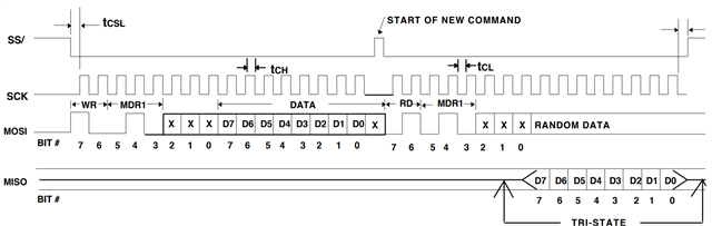
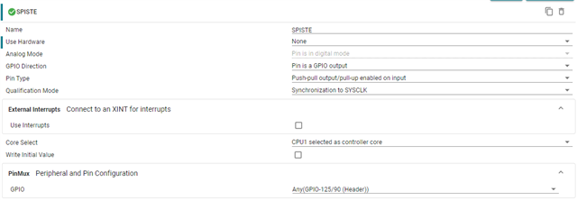
我设置了 SysConfig 设置、写入代码、并将 SPI 线路连接到示波器。 这些图片是我的 SysConfig 设置、代码和 示波器 信号截屏。


//#############################################################################
//
// FILE:   spi_ex1_loopback.c
//
// TITLE:  SPI Digital Loopback
//
//! \addtogroup driver_example_list
//! <h1>SPI Digital Loopback</h1>
//!
//! This program uses the internal loopback test mode of the SPI module. This
//! is a very basic loopback that does not use the FIFOs or interrupts. A
//! stream of data is sent and then compared to the received stream.
//! The pinmux and SPI modules are configure through the sysconfig file.
//!
//! The sent data looks like this: \n
//!  0000 0001 0002 0003 0004 0005 0006 0007 .... FFFE FFFF 0000
//!
//! This pattern is repeated forever.
//!
//!  \note This example project has support for migration across our C2000
//!  device families. If you are wanting to build this project from launchpad
//!  or controlCARD, please specify in the .syscfg file the board you're using.
//!  At any time you can select another device to migrate this example.
//!
//! \b External \b Connections \n
//!  - None
//!
//! \b Watch \b Variables \n
//!  - \b sData - Data to send
//!  - \b rData - Received data
//!
//
//#############################################################################
//
//
// $Copyright:
// Copyright (C) 2022 Texas Instruments Incorporated - http://www.ti.com
//
// Redistribution and use in source and binary forms, with or without
// modification, are permitted provided that the following conditions
// are met:
//
//   Redistributions of source code must retain the above copyright
//   notice, this list of conditions and the following disclaimer.
//
//   Redistributions in binary form must reproduce the above copyright
//   notice, this list of conditions and the following disclaimer in the
//   documentation and/or other materials provided with the
//   distribution.
//
//   Neither the name of Texas Instruments Incorporated nor the names of
//   its contributors may be used to endorse or promote products derived
//   from this software without specific prior written permission.
//
// THIS SOFTWARE IS PROVIDED BY THE COPYRIGHT HOLDERS AND CONTRIBUTORS
// "AS IS" AND ANY EXPRESS OR IMPLIED WARRANTIES, INCLUDING, BUT NOT
// LIMITED TO, THE IMPLIED WARRANTIES OF MERCHANTABILITY AND FITNESS FOR
// A PARTICULAR PURPOSE ARE DISCLAIMED. IN NO EVENT SHALL THE COPYRIGHT
// OWNER OR CONTRIBUTORS BE LIABLE FOR ANY DIRECT, INDIRECT, INCIDENTAL,
// SPECIAL, EXEMPLARY, OR CONSEQUENTIAL DAMAGES (INCLUDING, BUT NOT
// LIMITED TO, PROCUREMENT OF SUBSTITUTE GOODS OR SERVICES; LOSS OF USE,
// DATA, OR PROFITS; OR BUSINESS INTERRUPTION) HOWEVER CAUSED AND ON ANY
// THEORY OF LIABILITY, WHETHER IN CONTRACT, STRICT LIABILITY, OR TORT
// (INCLUDING NEGLIGENCE OR OTHERWISE) ARISING IN ANY WAY OUT OF THE USE
// OF THIS SOFTWARE, EVEN IF ADVISED OF THE POSSIBILITY OF SUCH DAMAGE.
// $
//#############################################################################


/*Included Files*/
#include "driverlib.h"
#include "device.h"
#include "board.h"
#include <stdio.h>


/*IR REG*/
//OP CODE
#define CLR_REG     0x00
#define RD_REG      0x40
#define WR_REG      0x80
#define LOAD_REG    0xC0

//SEL REG
#define MDR0        0x00 | (0b001 << 3)
#define MDR1        0x00 | (0b010 << 3)


/*MDR0 SETTING*/
#define MDR0_4QUAD_MODE  0x00 | 0b11

/*MDR1 SETTING*/
#define MDR1_4BYTE_MODE  0x00 | 0b00


#define STE_HIGH    GPIO_writePin(SPISTE, 1)
#define STE_LOW     GPIO_writePin(SPISTE, 0)
#define STE_STATE   GPIO_readPin(SPISTE)


/*private code*/
#define nData       2
uint16_t TxData[nData] = {0,};
uint16_t RxData[nData] = {0,};

/*Main*/
void main(void)
{
    /*start settings*/
    // Initialize device clock and peripherals
    Device_init();

    // Disable pin locks and enable internal pullups.
    Device_initGPIO();

    // Initialize PIE and clear PIE registers. Disables CPU interrupts.
    Interrupt_initModule();

    // Initialize the PIE vector table with pointers to the shell Interrupt
    // Service Routines (ISR).
    Interrupt_initVectorTable();

    // Board initialization
    Board_init();

    // Enable Global Interrupt (INTM) and realtime interrupt (DBGM)
    EINT;
    ERTM;


    /*USER CODE*/

    STE_HIGH;
    while(1)
    {
        STE_LOW;
        TxData[0] = (WR_REG | MDR0);
        TxData[1] = (MDR0_4QUAD_MODE);
        SPI_writeDataBlockingNonFIFO(mySPI0_BASE, (TxData[0] << 8U));
        SPI_writeDataBlockingNonFIFO(mySPI0_BASE, (TxData[1] << 8U));
//        DEVICE_DELAY_US(200);
        STE_HIGH;
        DEVICE_DELAY_US(20);

//        DEVICE_DELAY_US(1000);
//
//        STE_LOW;
//        SPI_writeDataBlockingNonFIFO(mySPI0_BASE, (RD_REG | MDR0) << 8U);
//        RxData[0] = SPI_readDataBlockingNonFIFO(mySPI0_BASE);
//        DEVICE_DELAY_US(20);
//        STE_HIGH;
//
//        DEVICE_DELAY_US(1000);
    }
}

//
// End File
//

CLK 只能在 STE ==低电平时工作、CLK 也能在 STE ==高电平时工作。
如果您看看主代码的逻辑、绝对没有理由使 CLK 工作、因为它在数据传输后将 STE 升高到高电平、但我不知道它为什么如此。
查看示波器波形、SPI_writeDataBlockingNonFIFO 和 STE 似乎独立运行。
这是因为 STE 和 GPIO 的操作吗? 我不知道为什么。。。
为了解决数据传输函数处于 STE==LOW 状态时不工作的问题、在 SPI_writeDataBlockingNonFIFO 和 STE_HIGH 之间任意指定了 DEVICE_DELAY_US (200)、并获取以下波形。
此时、观察 STE (=SS)波形时、低电平状态恰好保持在200us 左右。
我是按代码顺序编写的、但 GPIO 和 SPI 是独立移动的吗? 我该如何看待这个现象?
如果这是使用 GPIO 进行控制引起的问题、我应如何在 SysConfig 的 SPI 中设置该问题以连续发送两个8位数据?