工具与软件:
大家好!
我有一个从设备(MC33772B)、我想通过 SPI 与它进行通信。 这需要一条40位的消息、但不幸的是、我的电路板只能发送16位。
仍然可以通过电路板发送40位吗?或者它不是设计用于此目的吗? 或者我是不是在误会什么东西?
(隔离通信之间有一个 MC33664)

我会非常感谢任何小费。
此致
This thread has been locked.
If you have a related question, please click the "Ask a related question" button in the top right corner. The newly created question will be automatically linked to this question.
工具与软件:
大家好!
我有一个从设备(MC33772B)、我想通过 SPI 与它进行通信。 这需要一条40位的消息、但不幸的是、我的电路板只能发送16位。
仍然可以通过电路板发送40位吗?或者它不是设计用于此目的吗? 或者我是不是在误会什么东西?
(隔离通信之间有一个 MC33664)

我会非常感谢任何小费。
此致
您好!
请参阅此主题: LAUNCHXL-F28379D:通过 SPI 从 txt 文件发送24位字- C2000微控制器论坛- C2000 ︎ 微控制器- TI E2E 支持论坛
此致、
Aishwarya.
你好:)
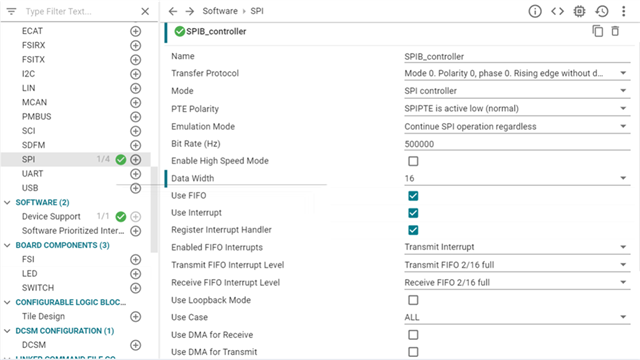
如果我在 sysconf 中将数据宽度设置为16、我可以根据需要插入此命令、从而可以在一个芯片选择中发送16位(此处为64位)的倍数: 


问题是40不是16的倍数。 这就是我在 sysconf 中将数据宽度设置为8的原因。 但是、我无法再执行 SPI_writeDataNonBlocking (SPIB_BASE、0xAA)。 在示波器上看不到任何数据(芯片选择和时钟可见、但不可见数据)。 为了能够发送8位的倍数、我还需要进行哪些更改、才能更频繁地执行命令?
我的代码:
#include "driverlib.h"
#include "device.h"
#include "board.h"

//
// Globals
//
volatile uint16_t receiveData;
volatile uint16_t slaveReady = 0;
volatile uint16_t masterReady = 0;
volatile uint16_t counter = 1;

//
// Function Prototypes
//
__interrupt void spibTxFIFOISR(void);
__interrupt void spiaRxFIFOISR(void);

//
// Main
//
void main(void)
{
    uint16_t i;

    //
    // Initialize device clock and peripherals
    //
    Device_init();

    //
    // Disable pin locks and enable internal pullups.
    //
    Device_initGPIO();

    //
    // Initialize PIE and clear PIE registers. Disables CPU interrupts.
    //
    Interrupt_initModule();

    //
    // Initialize the PIE vector table with pointers to the shell Interrupt
    // Service Routines (ISR).
    //
    Interrupt_initVectorTable();

    //
    // Board initialization
    //
    Board_init();
    //
    // Enable Global Interrupt (INTM) and realtime interrupt (DBGM)
    //
    EINT;
    ERTM;

    //
    // Loop forever. Suspend or place breakpoints to observe the buffers.
    //
    while (1)
    {
        ;
    }
}

//
// SPI B Transmit FIFO ISR
//
__interrupt void spibTxFIFOISR(void)
{
    uint16_t i = 0;

    //
    // Send data
    //

    while (i < 10000)
    {
        i++;
    }

    SPI_writeDataNonBlocking(SPIB_BASE, 0xAA);
    SPI_writeDataNonBlocking(SPIB_BASE, 0xAA);

    SPI_writeDataNonBlocking(SPIB_BASE, 0xAA);
    SPI_writeDataNonBlocking(SPIB_BASE, 0xAA);

    //
    // Clear interrupt flag and issue ACK
    //
    SPI_clearInterruptStatus(SPIB_BASE, SPI_INT_TXFF);
    Interrupt_clearACKGroup(INT_SPIB_controller_TX_INTERRUPT_ACK_GROUP);

}

//
// Enabled only for SysConfig functionality
//
__interrupt void INT_SPIB_controller_RX_ISR(void)
{
    //
    // Issue ACK
    //
    Interrupt_clearACKGroup(INT_SPIB_controller_RX_INTERRUPT_ACK_GROUP);

}

//
// End of file
//